3
AEG LOW VOLTAGE ENERGY STORAGE UNIT (8 KWH / 12 KWH) INSTALLATION MANUAL PD202107 V1-21EN
1. PRELIMINARY REMARKS
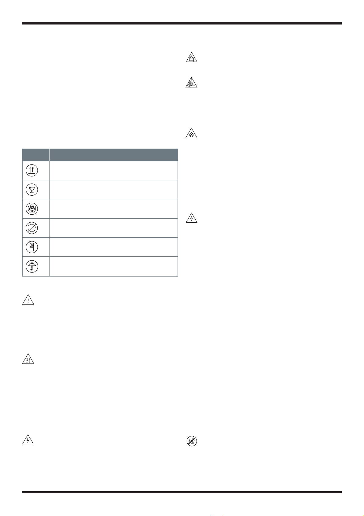
1.1 Icons
This section describes relevant warning symbols
recurring in the installation and operation manual of
AEG energy storage systems. Icons highlight relevant
information for the physical and property safety of
the user. Compliance to the provided instructions
is essential to prevent physical injury and product
damage. Below is a list of the icons used in this manual:
Icon Meaning Instruction
Danger Serious physical injury or
even death may occur in case
of noncompliance with the
requirement (electrical hazard)
Warning Physical injury or product
damage may occur in case of
noncompliance with the
requirement.
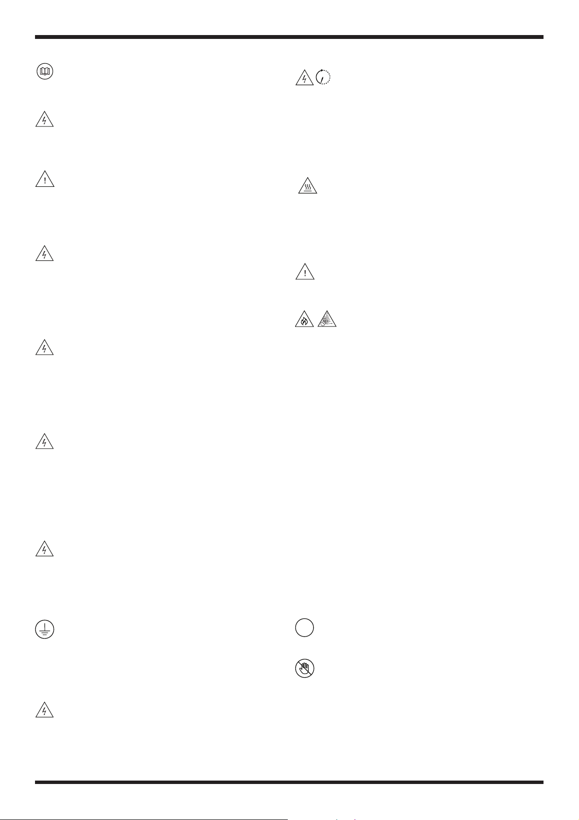
Electro-
static
discharge
Damage may occur in case of
noncompliance with the
requirement.
Hot
surface
Product surface may become
hot, do not touch
iNote Useful information for product
maintenance and operation is
provided
Table 1: Icon meaning
1.2 Product Identification
Energy Storage System:
Each energy storage system can be identified by means
of the following information:
Serial Number
Each storage unit is identified by a unique serial
number univocally coupled with a barcode, to be found
on the cabinet.
Product Label
The product label of the energy storage unit is placed
on the housing. It provides information about the main
parameters of the storage unit such as: Product Name
Code (PNC), Capacity, PV Input, AC Grid Port Input and
Output, O-Grid AC Output, Battery Data, and further
operation parameters.
HOME ENERGY STORAGE SYSTEM
MODEL (PNC): AS-BSL1-8000
CAPACITY
Nominal storage capacity (kWh)
Usable storage capacity (kWh)
PV INPUT
Max. recommended DC power (W)
Max. DC voltage (V)
MPPT voltage range (V)
Max. input current (A)
Max. short current (A)
Number of MPPT trackers
AC GRID PORT INPUT AND OUTPUT
Grid type
AC voltage (V"$)
Max. continuous power (W)
Max. AC apparent power (VA)
Max. AC output current (A)
Max. AC intput current (A)
Grid frequency/range (Hz)
Power factor range
OFF-GRID AC OUTPUT
Grid type
AC voltage (V"$)
Max. continuous power (W)
Max. AC apparent power (VA)
Max. AC output current (A)
Grid frequency/range (Hz)
Power factor range
BATTERY DATA
Battery type
Normal voltage (V)
Voltage range (V)
Max. charge/discharge current (A)
REGULAR PARAMETERS
Protective class
Ingress protection
Overvoltage category
Inverter topology
Operating temperature range (°C)
10 min
7.6 8
6.14
6500
500
125-425
11/11
16/16
2
Single phase (L/N/PE)
230
5000
5000
25
25
50
-0.8~+0.8
Single phase (L/N/PE)
230
5000
5000
25
50
-0.8~+0.8
Lithium (LFP)
51.2
42~58
100
Class I
IP 20
OVC II(PV) OVCIII(AC)
Non-isolated
-10~+40
AEG
is a registered trademark
used under license
from AB Electrolux (publ).
Solar Solutions GmbH
Brückenstrasse 94
60594 Frankfurt am Main
Germany
+49 69 800 500 810
www.aeg-industrialsolar.de
Product assembled in the P.R.C.
HOME ENERGY STORAGE SYSTEM
MODEL (PNC): AS-BSL1-12000
CAPACITY
Nominal storage capacity (kWh)
Usable storage capacity (kWh)
PV INPUT
Max. recommended DC power (W)
Max. DC voltage (V)
MPPT voltage range (V)
Max. input current (A)
Max. short current (A)
Number of MPPT trackers
AC GRID PORT INPUT AND OUTPUT
Grid type
AC voltage (V"$)
Max. continuous power (W)
Max. AC apparent power (VA)
Max. AC output current (A)
Max. AC intput current (A)
Grid frequency/range (Hz)
Power factor range
OFF-GRID AC OUTPUT
Grid type
AC voltage (V"$)
Max. continuous power (W)
Max. AC apparent power (VA)
Max. AC output current (A)
Grid frequency/range (Hz)
Power factor range
BATTERY DATA
Battery type
Normal voltage (V)
Voltage range (V)
Max. charge/discharge current (A)
REGULAR PARAMETERS
Protective class
Ingress protection
Overvoltage category
Inverter topology
Operating temperature range (°C)
11.52
9.22
6500
500
125-425
11/11
16/16
2
Single phase (L/N/PE)
230
5000
5000
25
25
50
-0.8 ~+0.8
Single phase (L/N/PE)
230
5000
5000
25
50
-0.8 ~+0.8
Lithium (LFP)
51.2
42~58
100
Class I
IP 20
OVC II(PV) OVCIII(AC)
Non-isolated
-10~+40
10 min
AEG
is a registered trademark
used under license
from AB Electrolux (publ).
Solar Solutions GmbH
Brückenstrasse 94
60594 Frankfurt am Main
Germany
+49 69 800 500 810
www.aeg-industrialsolar.de
Product assembled in the P.R.C.
Energy storage system label example
AS-BSL1-8000 AS-BSL1-12000
Icon Meaning
Safety warning: electrical hazard
10min
Wait at least 10 minutes after
disconnecting the inverter before
touching internal parts
Product surface may become hot, do not
touch
5.3.5 Accessing the statistics in the Data menu 25
5.3.6 Checking Fault messages 25
5.4 Advanced settings (for installers only) 26
5.4.1 Setting of battery parameters 26
5.4.2 Setting of grid parameters 26
Charging and Discharging settings of the AEG energy
storage system 27
5.4.3 Additional settings 27
6. TROUBLESHOOTING 27
6.1 Battery pack warnings and troubleshooting 27
6.2 Energy storage system warnings and
troubleshooting 28
6.2.1 Fault codes 28
6.2.2 Troubleshooting specific faults 29
7. GENERATOR AND AC COUPLING FUNCTION 30
8. PRODUCT END OF LIFE 30
9. DISCLAIMER OF LIABILITY 31
10. CONTACT 31