AEG installation manual 3
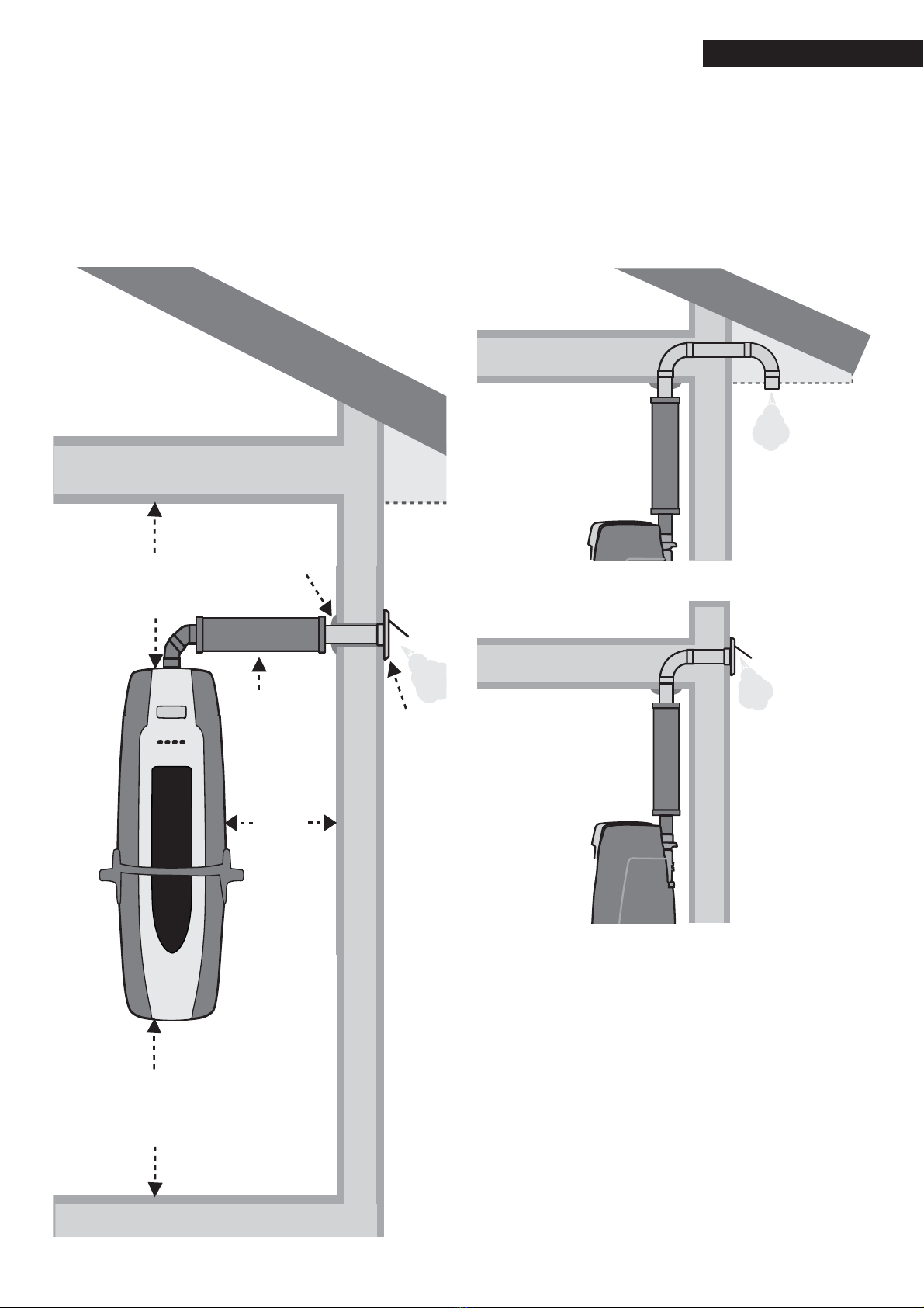
power unit exhaust
pipe
power unit
wall valve
hose coverage
Location of the Power Unit
Place the power unit preferably in a heated area like the utility room,
garage, storage room, or laundry room. If the power unit is installed in a
cold storage room, the vacuum tubing and the exhaust pipe should be
insulated in order to avoid condensation.
In buildings with two or more stories, it is recommended to always place
the power unit on the lowest floor. If the equipment is placed on the upper
floor, the power unit must be more powerful so that even the heaviest
dust particles can be vacuumed and transferred into the dust container.
When selecting the installation location, it is recommended that you
ensure that the placement does not disturb your neighbors or interfere
with your own comfort and activities. Make sure that there is a wall outlet
nearby for connection to the electrical network. If you are not sure about
the placement, contact your local building inspector or fire authority for
more information.
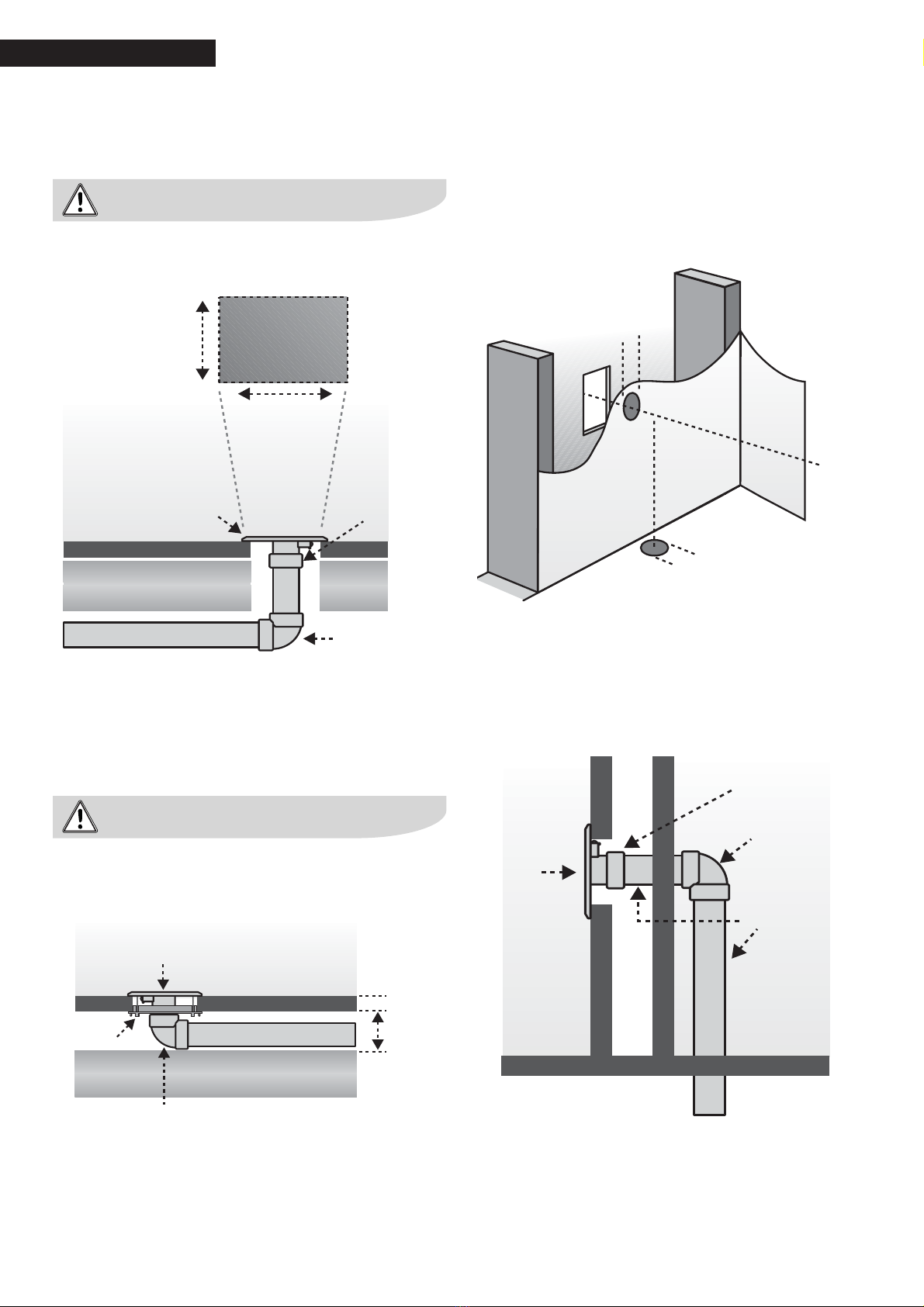
Location of Wall Inlet Valves
Wall inlet valves can be placed in the wall or in the floor. Place the inlets
preferably so that you can reach every corner of the room with a vacuum
hose that is 27 to 33 feet long (8m to 10m). There is a utility valve in the
power unit, which allows you to conveniently clean the space where the
vacuum is located and close-by areas, thus eliminating the need to install
another inlet valve and tubing route.
Marking the Placement of the Inlet Valves
Mark the installation points of the inlet valves in the layout drawings using
wire of the same length as the actual vacuum hose. When using drawings
scaled 1:1000 the wire length is 3 1/4” (8 cm), and when using drawings
scaled 1:50 the wire length is 6 1/2” (16 cm). Suitable places for inlet
valves are entrance halls, hallways, etc.
In a typical house only two inlet val-
ves are needed. In such cases, the
utility valve of the power unit can
be used for cleaning the basement
because it often covers the whole
basement area.
In this example, the main tube has
been routed under the house. Ho-
wever, the tube in the under-house
crawl space should be insulated to
avoid condensation.
The whole floor area can often be
vacuumed from one single inlet val-
ve. The light, broken line indicates
an alternative installation type.
In the house of the same size, the
power unit is in the garage, where
the utility valve serves as a third
inlet valve allowing you to clean
your car, for example.
wall
valve
door
Floor
valve
wall
valve
In this example, the simplest
solution is to route the tubing in
the attic. If the space is cold, the
main tube should be insulated.
It is recommended to place the
inlet valves in between different
levels. In such cases, you can ea-
sily clean two levels from one inlet
valve. The power unit is placed in
the storage room.
Typical Installation Examples
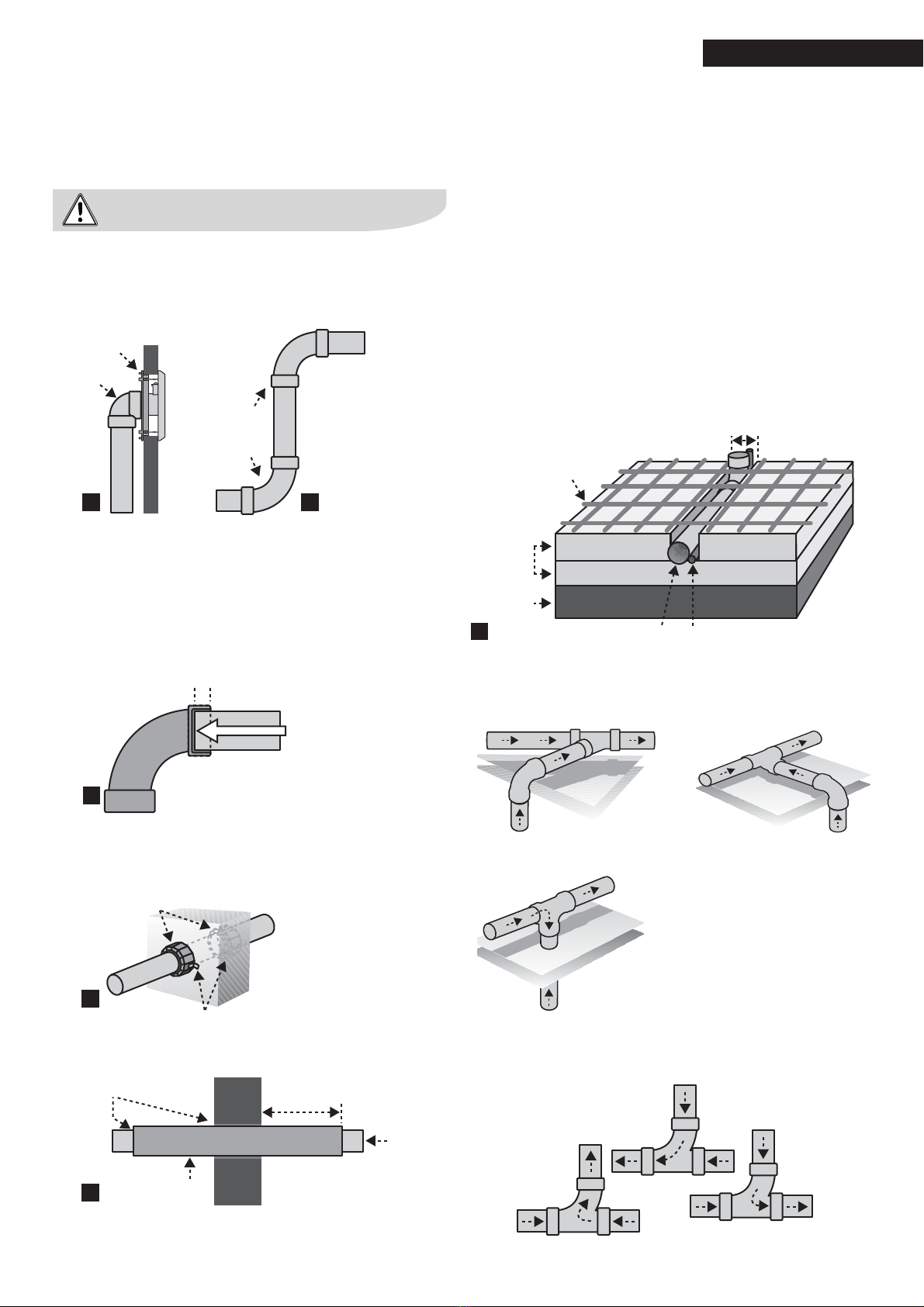
Tubing System Design
The main principle for designing the layout of the tubing system is to
keep it as short as possible. This will give the highest possible vacuum
performance. However, the main tube can be routed in different ways.
The outside diameter of the tubing system is 2” (50.08mm) and is 2 1/8”
(56mm) at the extension. The through-holes in the walls must be 2 3/16”
to 2 1/2” (55mm to 60mm) in diameter so that the extension and the low-
voltage cable can also go through the opening. The minimum diameter of
the exhaust tube is 2 1/8” (56mm).
New One-Story Houses
The horizontal main tube is placed in the under-house crawl space or in
the attic. In the under-house crawl space, the tubing should be insulated.
Tubes to the inlet valves are routed in the partition walls or between
secondary spaces, such as closets. In a cold attic, the tubes should be
covered with insulation in order to avoid condensation.
Two- or Multi-Story Houses
The main tube is placed in the under-house crawl space, attic, closet,
between walls, etc.
Existing Houses
The main tube can be installed on the surface in existing secondary
spaces, such as a garage or storage room. The tube can also be routed
through the attic and then vertically inside the partition walls and closets
all the way to the inlet valves. A lowered ceiling and closet footings can
also be used for routing of the tubes.
Read these instructions carefully. Installation of the central vacuum
system is easy and can be performed with regular hand tools. The
system can be installed both in new and existing buildings. When
using a central vacuum system, it is important to make sure there is
a sufficient compensation air supply. Normal ventilation ensures that
there is enough compensation air. This central vacuum system is very
useful, and you can enjoy it for years to come.