InterVac H User manual

THE COMPACT CENTRAL VACUUM SPECIALIST
RECORD THIS INFORMATION
FOR FUTURE REFERENCES
MODEL
NUMBER
____________________
DATE OF PURCHASE ________________
PLACE OF PURCHASE _______________
Manual # M-11 Rev.: 3/31/2022
INSTALLATION and OPERATING MANUAL
120 VOLT Model: H surface mounted with power cord attached
Model: RMH surface mounted with power cord attached
Model H Models RMH Model RMD, special order
IF YOU SHOULD HAVE ANY QUESTIONS OR EXPERIENCES A PROBLEM WITH YOUR INTERVAC
PRODUCT, DO NOT RETURN THIS PRODUCT TO THE STORE OR DEALER
PLEASE CALL US DIRECT 1-888-499-1925, we are here to help.
WARNING: Owner read carefully.
This manual must be read and understood before installation, adjustment, service, or maintenance is
performed. This unit should be installed by a qualified technician. Modification of this product can be extremely
hazardous and could result in personal injury or property damage. Instructions must stay with unit.
InterVac Design Corp., Palm City, FL 34990
2939 SW 42nd Avenue
Phone 772-463-1400 • USA & Canada toll free 888-499-1925
www.intervacdesign.com • e-mail: sales@intervacdesign.com

2
Polarization Instructions for models with 120volt cord only.
These appliances have a polarized plug (one blade is wider than the other). This plug will fit in a polarized
outlet only one way. If the plug does not fit fully in the outlet, reverse the plug. If it still does not fit, contact
a qualified electrician to install the proper outlet. Do not change the plug in any way.
When using an electrical vacuum cleaner, basic precautions should always be followed including the following:
Read all instructions carefully before using this vacuum cleaner.
WARNING:
TO REDUCE THE RISK
OF FIRE, ELECTRIC SHOCK, OR INJURY:
1. Unplug from electrical outlet when not in use and before
servicing.
2.
Do not use on wet surfaces.
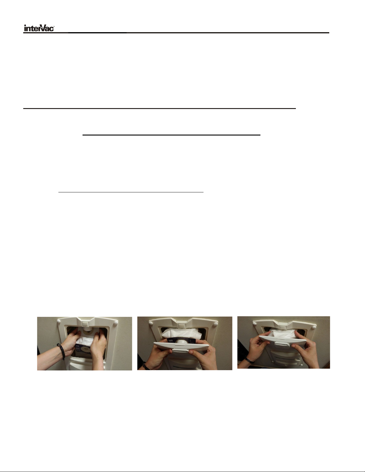
3. Never operate this vacuum cleaner without a dust bag and filters
in place.
4. Close attention is necessary when used by or near children.
Do not allow unit to be used as a toy.
5. Use only for intended use as described in this manual. Use only
the manufacturer's recommended attachments and dust bag.
6. Do not use with damaged cord or plug. If appliance is not working
as it should, has been dropped, damaged, left outdoors, or fell into
water, return the vacuum cleaner to InterVac or an authorized
service dealer for examination and repair.
7. Do not put any object into openings. Do not use with any openings
blocked; keep free of dust, lint, hair, and any other material that
may reduce air flow. If the secondary filter becomes dirty,
rinse in warm water or replace with a new filter. Filter should be
completely dry before using.
8.
Never drop or insert any object into any opening.
9.
Turn off all controls before unplugging.
10. Do not pull or carry by cord, do not use cord as a handle, do not
close a door on the cord, or pull cord around sharp edges or
corners. Do not run over cord. Keep cord away from
heated
surfaces.
11. Do not unplug by pulling on cord. To unplug, grasp the plug, not
the cord.
12. Keep hair, loose clothing, fingers, and all parts of body away
from any openings and all moving parts.
13. Do not pick up anything that is burning or smoking, such as
cigarettes, matches, or hot ashes.
14. Use extra caution when cleaning on stairs.
15. Do not handle plug or appliance with wet hands.
16. Do not pick up flammable or combustible liquids such as
gasoline or use in areas where they may be present.
17. Do not place objects against the vacuum cleaner. Keep area
clear.
18. Do not step on the hose or pull the hose forcibly.
19. Do not pick up large objects such as wastepaper or cloth,
which may clog the hose.
20. Do notinstall this vacuum cleaner in an area exposed to high
temperatures.
21. Install this vacuum cleaner in a dry place.
22. Do not attempt to service the vacuum cleaner. Unit is sealed
and cannot be opened without damage to the unit. For service,
call your local authorized service dealer, or InterVac Design's
Customer Care Center.
SAVE THESE INSTRUCTIONS
LIMITED WARRANTY
InterVac Design Corp. will repair the power unit with new or rebuilt parts, free of charge for two (2) years in North America from
the date of original purchase in the event of a defect in materials or workmanship. Warranty might vary from country to country.
No cash refunds. Excluded are the following items that require normal replacement:
Disposable
dust
bags,
filters,
vacuum
cleaner
tools,
and
vacuum
hoses.
This warranty is extended only to the original purchaser. A purchase receipt or other proof of date of original purchase will be
required before warranty performance is rendered.
You must return
your warranty
card
or register
on our
website to
be
covered under
these provisions
.
This warranty only covers failures due to defects in materials or workmanship which occurs during normal use and does not
cover damage which occurs in shipment or failures which are caused by products not supplied by InterVac Design, or failures
which result from accident, misuse, abuse, neglect, mishandling, misapplication, alteration, modification, or commercial use
such as hotel, office, restaurant or rental use of the product, or service by anyone other than an authorized service center, or
damage that is attributable to acts of God.
There
are
no
expressed
warranties
except
as
listed
above.
LIMITS AND
EXCLUSIONS
:
INTERVAC DESIGN SHALL NOT BE LIABLE FOR INCIDENTAL OR CONSEQUENTIAL DAMAGES RESULTING FROM
THE USE OF THIS PRODUCT OR ARISING OUT OF ANY BREACH OF THIS WARRANTY.
ALL EXPRESSED AND
IMPLIED WARRANTIES, INCLUDING THE WARRANTIES OF MERCHANTABILITY AND FITNESS FOR A PARTICULAR
PURPOSE, ARE LIMITED TO THE APPLICABLE WARRANTY PERIOD SET FORTH ABOVE.
Some states do not allow the exclusion or limitation of incidental or consequential damages or limitations on how long an
implied warranty lasts, so the above exclusions or limitations may not apply to you. This warranty gives you specific legal rights
that vary from state to state. If a problem with this product develops during or after the warranty period, you may contact your
dealer or our service center.
If the problem is not handled to your satisfaction, then write to the Customer Service Center at the
company address.
IMPORTANT SAFETY INSTRUCTIONS

3
Specification: 120 Volt, 10 Amp high efficiency Motor, 50/60Hz, 530 air watts, Weight 8 lb.
Parts List:
Depending on model
Paper template: L-40 4 screws and caps
3 wire nuts, when installed flush in a stud wall 2 high filtration bags #Y08 or #Y09 (RMD only)
1 plywood strip for dry-wall installation
CAUTION:
To avoid possible electrical shock, be sure that electricity is turned off at the
main
switch or circuit breaker. All wiring must be in accordance with the US National Electric
Code or Canadian Electric Codes.
WARNING: Electrical connections should be made by a qualified electrician.
CAUTION:
DO NOT PICK UP LIQUIDS, LIT CIGARETTES, HOT ASHES,
RAZOR BLADES, NEEDLES, PINS OR OTHER SHARP OBJECTS!
INSTALLATIONS
MODEL: H-Surface Mounted with power cord attached,
External to Wood or Dry-wall Surfaces:
(see Fig.: A)
Step 1.
To cover with the vacuum hose as much area as possible, choose a wall or surface that is
centrally located and has an electrical outlet close by.
Step 2.
Cut paper template from the instruction manual, last page.
Align the 2 vertical mounting holes on the template with the center of a stud behind the dry-wall
and tape the template to the wall or a surface at a comfortable operating height or a minimum
of 2 to 3 inches above the floor.
Mark the 4 centers accurately.
Carefully remove template from the wall and place it into the operating manual for future references.
Step 3.
Attach 2 #8 screws into the dry-wall stud and use the other 2 screws with the wall anchors,
(drill 5/16 hole). Keep the screw heads 1/8” from the wall.
Step
4
.
Slide the key holes on the back of the vacuum cleaner over the 4 screw heads and secure
by pushing down. If vacuum cleaner is loose re-tighten screws a little more.
TIP:
If vacuum cleaner is mounted on its back or side, it may slide off the screw heads when you pull on the vacuum hose.
To prevent this, fasten a small wood block against the top of the unit.
Step
5
.
Check to be sure dust bag and motor filter (under dust bag) are in place.
The corners of the motor filter must be tucked under the ribs so that the filter lays flat!

4
Model: RMH with electric cord attached
Paper Template #L-40
Surface Mounted to Wood or other Stable Surfaces (see Fig.: A)
Step 1. To reach with the vacuum hose as far as possible, find a central location for the vacuum valve and a mounting
position for the vacuum as close as possible to the vacuum valve. An electrical receptacle must be nearby.
Step 2. Tape the paper template, page 16, for the vacuum to the wall a minimum 2” above the floor, so that the
exhausting air is not restricted. Mark the 4 screw positions with a pointed tool accurately.
Step 3. Attach the enclosed #8 screws to the wall as marked on the template. Keep the screw heads1/8” off the wall.
Step 4. Carefully remove template from the wall and place it into the operating manual for future references.
Step 5. Slide the key holes on the back of the vacuum cleaner over the 4 screw heads and push down.
If vacuum cleaner is loose re-tighten screws.
TIP: If vacuum cleaner is mounted on its back or side it may slide of the screw heads when you
pull on the vacuum hose. To prevent this, fasten a small block against the top of the unit.
Step 6. Attach the flanged pipe fitting (supplied) on top of the vacuum with the 4 screws provided.
Step 7. Install the remote vacuum valve (see page 8). Then route the flex-hose from the valve to the vacuum.
Step 8. From the remote vacuum valve install two 18-gage, UL approved (AVLV2) rated minimum
300volt, 95 C, wires (24-volt line) along the flex-hose to the bottom of the vacuum to the 2 yellow pigtails.
Secure the wires with “ty-wraps” to the flex-hose. Connect yellow wires with butt connectors outside the housing.
Step 9. Plug the electric cord into the receptacle.
Step 10. Test unit for proper operation by inserting the end of the vacuum hose into the remote valve.
Please, check that dust bag and motor filter (under dust bag) are installed. Motor filter should lay flat on
all 4 corners under the ribs!
IMPORTANT: If installed during new construction, do not use to clean up building debris.
For household use only. Nails and sharp objects can damage your InterVac.
WIRING INSTRUCTIONS:
Please Note: Models Hand RMH have power cords attached
Vacport
Vacuum Valve
Hard wire set-up
for RMD
BLACK
WIRE
WHITE WIRE
GREEN WIRE,
GROUND
2 YELLOW, low
voltage wires, 24 Volt
Yellow, 24-volt wire pigtails
are only supplied for RMD
models

5
Model RMF In-Wall Mounted, hard wired connection, Romex
Recessed Mounted into Wood Surface (see Fig.: B)
NOTE: Installation should be accessible from the back to install pipe fittings and wiring connection.
Step 1. Attach paper template to wall or surface about 2” inches or higher above the floor, so that the exhausting air,
coming out of bottom of the vacuum, is not restricted.
Step 2. At the lower right side of the unit, remove the 2-3/4 x 1-3/8 access cover plate on the vacuum cleaner.
Coming out of the bottom of the vacuum you will find black, white and green wires for the 120-volt power connection.
Pull them through the access cover opening on the lower right side.
Step 3. Install 14 gage AWG 300V Romex cable from your 120volt electric power supply and push the cable
through the Romex clamp, on the bottom of the vacuum, into the vacuum cleaner.
connect black to black, white to white and green to bare ground conductor wires with the supplied wire nuts.
push the connected wires back into the housing, Tighten Romex clamp and replace the side cover.
Step 4. 2 yellow wire pigtails for the 24-volt control circuit protruding out of the bottom of the vacuum.
Do not pull wires back into housing. Use butt connector, if available, for wiring to the vacuum valve.
Step 5. Install the remote vacuum valve(s) first and then the 2” dia. flex-hose.
After vacuum is installed, fasten the flanged fitting to the top of the vacuum by using the provided four #6 screws.
Step 6.
Now, attach the threaded pipe fittings to the flex-hose and then to the remote inlet valve. see page 8.
Step 7. From the remote vacuum valve install two 18 or 20 gage, UL approved wires (24-volt line) along the flex-hose
to the bottom of the housing to the 2 yellow pigtails.
Secure the wires with “ty-wraps” to the flex-hose. Connect wires with butt connectors outside the housing.
Step 8. Place the vacuum cleaner with bottom first in the cut-out and secure with the 4 screws and caps provided.
Step 9. Please, check that dust bag and motor filter (under dust bag) are installed.
Motor filter should lay flat on all 4 corners under the ribs!
Test unit for proper operation by inserting the end of the vacuum hose into the remote valve.

8
FITTING ASSEMBLY: AF-01-E, AF-01-W E=ebony, W=white
1 VALVE and FITTINGS for MODELS: CS-RM and RM
AS-40-E Black, valve/reducer
AS-40-W White P30 pipe to pipe coupling
D900 threaded coupling
TO FLANGED INTAKE
FITTING
ON POWER UNIT
if you use the spigot elbow,
P21, the spigot side must
be glued to the reducer
Please Note:
X640 Flex Hose,
4 FEET
TO POWER UNIT
INTAKE FITTING
use P20 pipe elbow
instead of P30 coupling,
if needed
Counterclockwise, screw threaded coupling
into flex-hose. Press-fit the other side into the fittings
with a strong twist. No need to glue.
Intake fitting is supplied in the power units vacuum chamber
FITTING ASSEMBLY: AF-10-E,
AF-10-W (ebony, white)
1 VALVE, VACPORT/LED (sweeper pan) and 45° WYE "T" for MODELS: CS-RM, RM and RMD
AS-40-E ebony, valve/reducer
AS-40-W white
P40
45° WYE "T"
P30 Pipe to Pipe
STANDARD coupling
TO FLANGED INTAKE
FITTING
ON POWER UNIT
D900 threaded Hose Coupling
6 required
A900-E VacPort, LED, black
A900-W white
P30 Pipe to
Pipe Coupling
attached
D900 Threaded Coupling
Please Note:
TO POWER UNIT
use P20 pipe elbow
instead of P30 coupling,
if needed
# X640 FLEX-HOSE, 6 FEET
INCLUDE 8 FEET OF LOW VOLTAGE WIRE
Counterclockwise, screw threaded coupling
into flex-hose. Press-fit the other side into the fittings
interVac Design
Palm City, FL. 3-2016
rev.: 9-2017
include 6 feet of low voltage wires

9
HOW TO OPERATE MODEL: H
NOTE: THE LOWER PART OF THE VACUUM CLEANER WILL BE QUITE WARM WHEN IN USE.
IF THE VACUUM STOPS RUNNING:
Most likely the vacuum hose is clogged, and the motor shuts off. Push the switch into OFF position
and let the motor cool down. Restart the vacuum without the vacuum hose attached for 10 minutes
and keep the small cover on the door open. If vacuum keeps running the hose or the tools are clogged.
PLEASE SEE TROUBLE SHOOTING GUIDE page 12.
A. Connecting and disconnecting the hose.
1. Lift the inlet valve cover on the front of the door.
2. Insert hose cuff with a twist and push to secure, friction fit.
3. To remove, turn hose in either direction while pulling hose towards you.
B. On / Off Switch
1. Do not run vacuum without hose attached.
2. To start the vacuum cleaner, push the switch to the “I” position.
3. To stop the vacuum cleaner, push the switch to the “O” position.
C: How to change the dust bag, DO NOT REUSE DUST BAG
Replacement bag: Part # Y08 high filtration 5-layer fiber bag.
1. Open the door on the vacuum cleaner by pushing the latch upward and remove both door and dust bag.
2. Carry door and dust bag to the trash container. Remove full bag and discard.
3. Place a new dust bag all the way over the pipe on the door.
4. When closing door, tuck in the top edge of the bag, so the door is properly sealed, and the
latch clicks into place.
TIP: If you break off the vacuum hose inlet cover on the door; simply reattach it by lining up one of the small dimples
located on the inside of the inlet covers arms and then press hard on the other side to click into position.
attach collar of dust bag
over black pipe
push the cardboard collar of
the bag tight against the door
push the top edge of the bag inside
the vacuum when closing the door
C: To change motor filter, Replacement Part # Y21 (see Fig.: E)
1. Remove door and dust bag.
2. Reach into the cavity towards the bottom of the vacuum cleaner and remove the motor filter.
3. Replace the filter with a new or cleaned filter and tuck in the corners so that the filter lays flat on the grid,
4. If necessary, clean the dirty filter by vacuuming or washing in mild soap by hand.

10
HOW TO OPERATE YOUR MODEL RMH
NOTE: THE LOWER PART OF THE VACUUM CLEANER CAN BE QUITE WARM.
IF THE VACUUM STOPS RUNNING:
Disconnect the vacuum hose from the unit and let the vacuum cool.
The thermal protector on the motor will reset itself after the motor is cooled.
The most likely cause will be a full bag or clogged vacuum hose or tools.
PLEASE SEE TROUBLE SHOOTING GUIDE. Page 12
A. Connecting and disconnecting the hose.
1. Lift inlet valve cover on the remote mounted valve.
2. Insert the vacuum hose cuff with a twist and push in. The vacuum cleaner will start automatically.
3. To remove, turn hose in either direction while pulling hose towards you.
The vacuum cleaner will stop running.
B. How to change the dust bag, Replacement Part # Y08 DO NOT REUSE DUST BAG
1. Open the door on the vacuum cleaner by pushing the latch upward and remove door completely.
2. Remove full bag and discard.
3. Locate the pipe inside the vacuum chamber. Holding the new bags cardboard collar at approximately
a 45-degree angle and pushing the cardboard part of the bag against upper back corner of the vacuum cleaner
chamber behind the pipe fitting. Lift the front of the collar over the fitting as far as possible.
4. When closing door, tuck-in the left and right corners of the bag, so the door is properly sealed, and
the latch clicks into place.
NEVER OPERATE THE VACUUM CLEANER WITHOUT THE DUST BAG OR THE MOTOR FILTER.
C: To change motor filter, Replacement Part # Y21 (see Fig.: E)
1. Remove door and dust bag.
2. Reach into the cavity towards the bottom of the vacuum cleaner and remove the motor filter.
3. Replace the filter with a new filter and tuck-in the corners so that the filter lays centered and flat on the
grid, with the straight side towards the back.
4. If you need to; clean the dirty filter by vacuuming or washing in mild soap by hand.
Do not clean in washing machine.
Let filter dry completely.
E: Replacing Motor Filter
Part #Y21 for all models.
Tuck-in the corners and sides under the vertical ribs

11
MODEL RMD
with Electric Cord or Permanent Installation
Please note: the installation for the model RMD is the same as for the models RM
You can insert the vacuum hose in the door on the front panel as well as
in the remote mounted vacuum valve.
When inserting the vacuum hose into the front panel you must use the switch
to start and stop the vacuum.
Insert vacuum hose first before turning the switch to ON.
NOTE: Do not run vacuum without hose attached or inlet cover open!
HOW TO OPERATE YOUR MODEL RMD
NOTE: THE LOWER PART OF THE VACUUM CLEANER CAN BE QUITE WARM.
IF THE VACUUM STOPS RUNNING:
Disconnect the vacuum hose from the unit and let the vacuum cool.
The thermal protector on the motor will reset itself after the motor is cooled.
The most likely cause will be a full bag or clogged vacuum hose.
PLEASE SEE TROUBLE SHOOTING GUIDE. Page 12
A. Connecting and disconnecting the vacuum hose.
1. Lift inlet cover on the remote valve. Insert the hose cuff with a twist and push, vacuum will start automatically.
2. Lift the flap on the door insert the hose and turn the switch on the front panel to ON.
3. To remove, flip switch to OFF, and then twist and remove hose in either direction while pulling hose towards you.
B. How to change the double collar dust bag, Replacement Part # Y09 DO NOT REUSE DUST BAG
1. Open the door on the vacuum cleaner by pushing the little latch upward and remove door completely.
2. The dust bag has 2 cardboard collars, a collar with arrows and a printed collar.
3. Locate the pipe inside the vacuum chamber. Holding the arrow cardboard collar at approximately
a 45-degree angle, push the cardboard part of the bag against upper back corner of the vacuum cleaner
chamber behind the pipe. Lift the front of the collar over the pipe as far as possible. Then attach the printed
collar to the pipe at the door. Slide the bottom of the bag into the vacuum chamber and secure the door.
4. When closing door, tuck-in the left and right corners of the bag, so the door is properly sealed, and
the latch clicks into place.
NEVER OPERATE THE VACUUM CLEANER WITHOUT THE DUST BAG OR THE MOTOR FILTER.
Attach to inside pipe Attach to pipe on the door Tuck in the corners before closing
C: To change motor filter, Replacement Part # Y21 (see Fig.: E)
1. Remove door and dust bag.
2. Reach into the cavity towards the bottom of the vacuum cleaner and remove the motor filter.
3. Replace the filter with a new filter and tuck-in the corners so that the filter lays centered and flat on the
grid, with the straight side towards the back.
4. If you need to; clean the dirty filter by vacuuming or washing in mild soap by hand.
Do not clean in washing machine.
Let filter dry completely and reuse as needed.

12
Fig.: E
E. Replacing
all Models,
D: Replacing Exhaust Filter,
Part #Y41: IF SUPPLIED,
Pinch exhaust filter in the middle and pull out.
To replace, pinch in the middle and slide in
one side first. (Washable by hand)
motor filter,
Part # Y21
tuck-in the corners and sides
carefully under the ribs
TROUBLE SHOOTING:
TIP: If you use our very convenient stretch hose, but require more suction power, we recommend you try
a traditional crush-proof central vacuum hose.
IF MOTOR SUDDENLY STOPS:
1. The most common cause is a clogged hose. Disconnect vacuum hose from cleaner, hold one end
high up in the air and drop a quarter or similar object into the hose. If the quarter gets
stuck the hose is clogged. Try to unclog the hose with a long stick or see below “cleaning the hose”.
2. The bag is overfilled, or fine dust has clogged the bag. Replace with new bag.
DO NOT EMPTY AND REUSE, if you reuse the bag the pores in the bag would be clogged, you will lose
vacuum suction.
3. The vacuum cleaning tools are clogged.
4. Vacuuming large amounts of dust other than household dirt, such as dry-wall or fine wood dust can
block the bags pores fast, even if the bag is new.
5. The motor filter is dirty and should be cleaned or replaced.
6. If vacuum unit is installed in an airtight compartment the exhausting air cannot escape, the motor
can overheat and shut off until it cooled down and is restarted.
7. The exhaust filter should be checked and replaced or cleaned.
IF YOU LOSE SUCTION:
1. The door is not properly closed, the dust bag is clamped behind the door and door frame.
2. For RM and RMD units only: the gray 2” diameter hose connecting the vacuum to the valve(s) might have
fallen off the connecting fittings.
3. If you have trouble finding the problem, please call us direct, we are here to help.
CLEANING THE STRETCH HOSE:
The stretch hose, besides all its’ conveniences, tends to get clogged.
a)
Lift the hose up on both ends and dispense some liquid detergent into both ends.
b)
With a garden hose, holding both ends still up, add ¾ with water.
c)
Shake hose up and down, let detergent loosen the dirt.
d)
Stretch the hose as far as you can (2 people required) and wash the dirt out with the full pressure of the
garden hose. Repeat if necessary.

13
ACCESSORIES
30 Feet Traditional
Central Vacuum Hose
PART #AS-20 for Models H, F
OPTIONAL VACUUM TOOLS
Dust Sweeper Inlet Valve
PART# AS-21 for all RM Models Elongated Dust Brush
PART# X251
Air Turbo Nozzle "VacPort.com" for RM Models
PART# X451 Model A910 w/o LED light
Model A900 with LED light
INTERVAC reserves the right to make improvements and modifications without notice.
Crevice Tool
Floor/Rug Tool
REPACEMENT DUST BAGS:

14
GarageVac Models
GF-
120
In-wall installation
where the unit fits
flush into a 2x4
stud wall.
Space saving.
Can also be flush
mounted into a
garage cabinet.
Minimum wall
space required.
GH-
120
surface
mounted in the
hobby shop.
Can easily be
moved to
another
location.
Compact and
very fast
excess to
vacuum tools
and hose
Model GH-120
Install the vacuum
close to the garage
door. This way
cars can be
reached inside and
outside the
garage.
Most effective
installation.
Minimal wall
Model AS-33
Remote Control RFI system
for all CSRM, RM models
and other central vacuums.
The pistol grip is easy to
attach to a vacuum hose.
The LED switch starts / stops
the vacuum
The receiver box with electric
cord mounts next to the
central vacuum power unit.
other InterVac Models
Model RM-H
Installed as a traditional
central vacuum system
with a vacuum valve in
the living room and the
power unit on the other
side of the wall, it could
be the garage, utility
room or closet.
see our website:
www.intervacdesign.com
Model H
(GF120 without
the tool caddy)
Installed in the
hallway of a town house.
Easiest and lowest
cost of having a
central vacuum in your
home.
see our website:
www.intervacdesign.com

8
TEMPLATE for SCREW CENTERS
for surface mounting vacuum
Template #L-40 (W600)
Modele papier # L-40 (W600)
pattern of keyholes from
the back of the vacuum.
modele de serrure a
l'arriere de l'aspirateur
2 anchor for drywall, horizontal
2 dispositif d'ancrage pour la
cloison sèche seulement, horizontale
mark all 4 centers accurately
marquer tous les 4 centres
avec précision.
keep screw heads 1/8" from the wall.
gardez les têtes de vis à 3.2mm du mur.
7 [174.59]
C U T
ALONG
DOTTED
LINE,
save
template
for
future
references
Couper le long de la ligne en pointillé, enregistrez le mod èle pour les futures références
Installing Vacuum to a wall stud
Use 2 screws without plastic anchors for the wall stud.
Use 2 anchors and 2 screws for the other side.
Installation de l'aspirateur à un poteau mural
Utiliser des 2 vis sans ancrages en plastique pour le poteau.
Utiliser 2 ancrages et 2 vis pour l'autre côté.
51
8
[130.18]
16
Plan
d'installation
L-40 de surface en bois et en cloison sèche
.
6
This manual suits for next models
1
Table of contents
Other InterVac Central Vacuum System manuals