AEMC 6255 User manual

ENGLISH
User Manual
■
MICRO-OHMMETER
6255
www. .com information@itm.com1.800.561.8187

Statement of Compliance
Chauvin Arnoux®, Inc. d.b.a. AEMC®Instruments
certifies that this instrument has been calibrated using
standards and instruments traceable to international
standards.
We guarantee that at the time of shipping your
instrument has met its published specifications.
An N.I.S.T. traceable certificate may be requested at
the time of purchase, or obtained by returning the
instrument to our repair and calibration facility, for a
nominal charge.
The recommended calibration interval for this
instrument is 12 months and begins on the date of
receipt by the customer. For recalibration, please use
our calibration services.
Serial #:
Catalog #: 2129.84
Model #: 6255
Please fill in the appropriate date as indicated:
Date Received:
Date Calibration Due:
Chauvin Arnoux®, Inc.
d.b.a AEMC®Instruments
2Micro-Ohmmeter Model 6255
www. .com information@itm.com1.800.561.8187

CONTENTS
1. INTRODUCTION............................................................................................4
1.1. Precautions .........................................................................................4
1.2. Battery Handling..................................................................................5
1.3. Definition of Measurement Categories (CAT)......................................5
1.4. Receiving Your Shipment....................................................................6
1.5. Ordering Information ...........................................................................6
2. FEATURES....................................................................................................7
2.1. Description ..........................................................................................7
2.2. Applications.........................................................................................7
2.3. Key Features.......................................................................................8
2.4. Control Features.................................................................................. 9
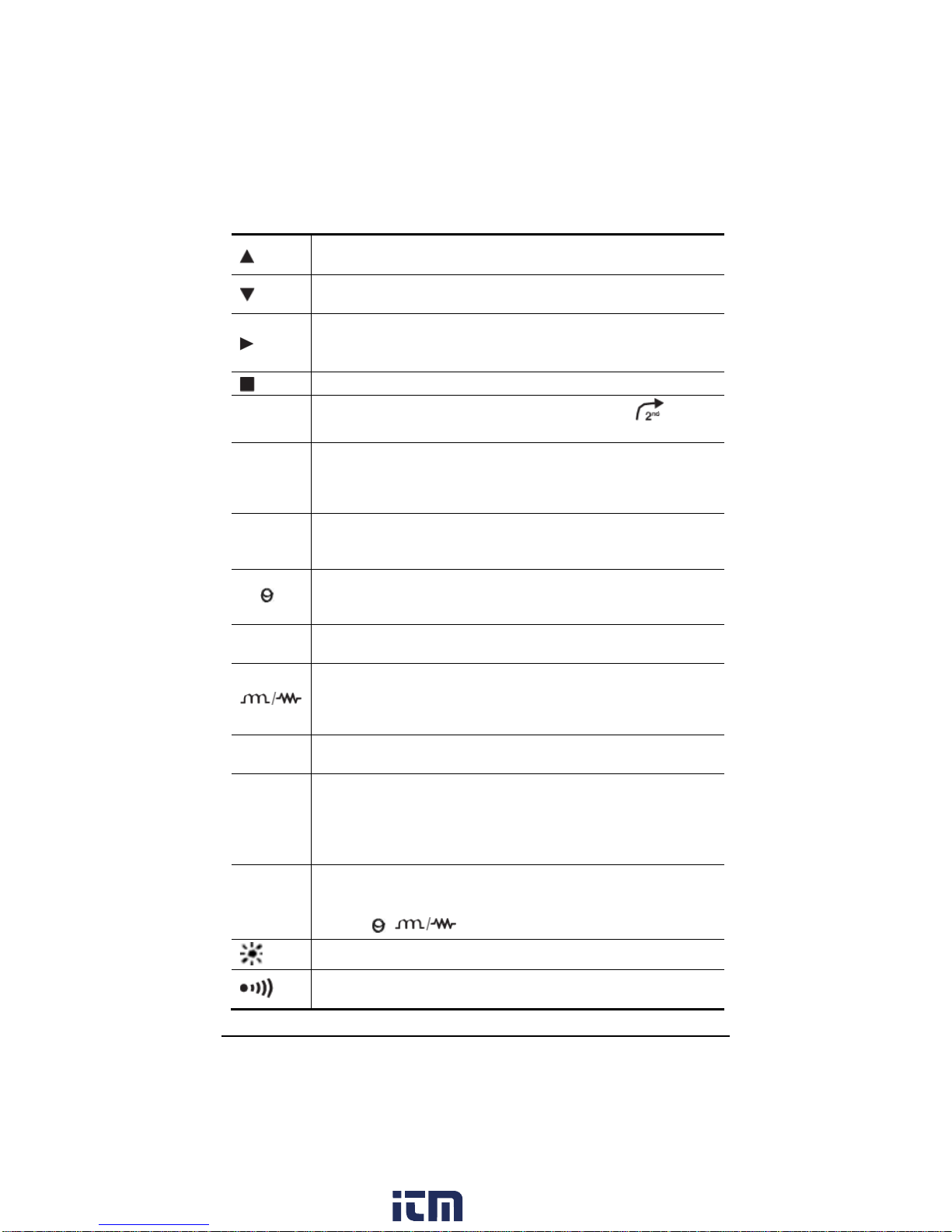
2.5. Button Functions ...............................................................................10
2.6. Display Symbols................................................................................ 11
3. SPECIFICATIONS....................................................................................... 13
3.1. Electrical............................................................................................13
3.2. Mechanical........................................................................................14
3.3. Display...............................................................................................14
3.4. Environmental ...................................................................................14
3.5. Safety................................................................................................ 14
4. OPERATION................................................................................................ 15
4.1. Quick Summary.................................................................................15
4.2. Instrument Configuration (SET-UP Mode).........................................17
4.3. Operating Procedure......................................................................... 26
4.4. Selecting the Test Range.................................................................. 28
4.5. Measurement Modes.........................................................................29
4.6. Ambient Temperature Compensation................................................ 33
4.7. Activating Alarms...............................................................................36
5. MEMORY/PRINTING................................................................................... 37
5.1. Managing and Printing the Data in Memory ......................................37
5.2. Displaying and Printing Stored Measurements..................................38
5.3. Cables and Printers Used with the Interface Port..............................40
6. DATAVIEW.................................................................................................. 42
7. TROUBLESHOOTING................................................................................. 43
7.1. Fault Indicators.................................................................................. 43
8. APPLICATION EXAMPLES ........................................................................ 44
8.1. Measuring Winding Resistance of Motors and Transformers............44
8.2. Measuring Resistance on Electric Motors......................................... 45
8.3. Battery Strap Measurements.............................................................45
9. MAINTENANCE........................................................................................... 46
9.1. Warning.............................................................................................46
9.2. Cleaning............................................................................................46
9.3. Charging/Recharging the Battery......................................................46
9.4. Battery and Fuse Replacement.........................................................47
REPAIR AND CALIBRATION ........................................................................... 48
TECHNICAL AND SALES ASSISTANCE....................................................... 48
LIMITED WARRANTY...................................................................................... 49
Micro-Ohmmeter Model 6255 3
www. .com information@itm.com1.800.561.8187

1. INTRODUCTION
Thank you for purchasing the AEMC Micro-Ohmmeter Model 6255. For best
results from your instrument and for your safety, read the enclosed operating
instructions carefully and comply with the precautions for use. These products
must be only used by qualified and trained users.
WARNING, risk of DANGER! The operator must refer to these
instructions whenever this danger symbol appears.
CAUTION! Risk of electric shock. The voltage at the parts marked
with this symbol may be dangerous.
Equipment is protected by double insulation.
Battery
Important instructions to read and to fully understand.
Useful information or tip to read.
Compliance with the Low Voltage & Electromagnetic Compatibility
European directives (73/23/CEE & 89/336/CEE)
In the European Union, this product is subject to a separate collection
system for recycling electrical and electronic components In
accordance with directive WEEE 2002/96/EC
1.1. Precautions
Refer to the following warnings to ensure personnel safety and proper instrument
operation.
Read the user manual before performing any tests with this instrument.
Only test de-energized circuits. Never connect to a live circuit.
When measuring resistance with a high inductive component
(transformers, motors, etc.), after ending the measurement the
instrument discharges the inductive sample and the warning icon
appears for the entire duration. Never disconnect the connection wires
before this icon disappears.
Do not use the instrument in an explosive environment, including poorly
ventilated battery rooms and enclosures.
Ensure the battery is fully charged prior to testing. If unused for several
months, recharge the battery. (We recommend monthly recharging.)
Use only direct replacements for blown fuses.
Do not use alcohol or oil based cleaners when cleaning the instrument.
Only use soapy water with a damp cloth or sponge.
Test leads and measuring wires must be in good condition; replace
immediately if there is any deterioration (insulation split, burnt, etc.).
Never exceed the safety values indicated in the specifications.
4Micro-Ohmmeter Model 6255
www. .com information@itm.com1.800.561.8187

1.2. Battery Handling
Your instrument is equipped with a NiMH battery. This technology offers
several advantages:
Long battery charge life for a limited volume and weight.
Possibility of quickly recharging your battery.
Significantly reduced memory effect: you can recharge your battery
even if it is not fully discharged.
Respect for the environment: no pollutant materials such as lead or
cadmium, in compliance with the applicable regulations.
After prolonged storage, the battery may be completely discharged. If so, it
must
be completely recharged. Full recharging of a completely discharged
battery may take several hours. The instrument cannot be used when the
battery is being recharged.
At least 5 charge/discharge cycles will be necessary for your battery
to recover 95% of its capacity.
To maximize battery life:
Only charge your instrument at temperatures between 32° and 104°F
(0° and 40°C).
Comply with the conditions of use defined in this user manual.
Comply with the storage conditions specified in this user manual.
NiMH technology allows a limited number of charge/discharge cycles
depending significantly on:
The conditions of use.
The charging conditions.
See §9 for battery replacement instructions.
Do not dispose of the battery pack with other solid waste. Used
batteries must be entrusted to a qualified recycling company or to a
company specialized in processing hazardous materials.
1.3. Definition of Measurement Categories (CAT)
CAT IV Measurement category IV corresponds to measurements taken at
the source of low-voltage installations.
Example: power feeders, counters and protection devices.
CAT III Measurement category III corresponds to measurements on
building installations.
Example: distribution panel, circuit-breakers, machines or fixed
industrial devices.
CAT II Measurement category II corresponds to measurementstaken on
circuits directly connected to low-voltageinstallations.
Example: power supply to domestic electrical appliances and
portable tools.
Micro-Ohmmeter Model 6255 5
www. .com information@itm.com1.800.561.8187

1.4. Receiving Your Shipment
Upon receiving your shipment, make sure that the contents are consistent
with the packing list. Notify your distributor of any missing items. If the
equipment appears to be damaged, file a claim immediately with the carrier
and notify your distributor at once, giving a detailed description of any
damage. Save the damaged packing container to substantiate your claim.
1.5. Ordering Information
Micro-ohmmeter Model 6255 …..………...........................….... Cat. #2129.84
Includes extra-large tool bag, set of two 10 ft. (3m) Kelvin clips (10A - Hippo),
set of two 10 ft. (3m) Kelvin probes (1A - Spring Loaded), one RS-232 DB9
F/F 6 ft. null modem cable, RS-232 to USB adapter, US 115V power cord,
quick reference guide, NiMH rechargeable 6V battery pack, and USB thumb
drive supplied with user manual and DataView®software..
Replacement Parts:
Kelvin Clips 10 ft. (3m) 10A-Hippo..…….……................…......... Cat. #1017.84
Kelvin Probes 10 ft. (3m) 1A Spring Loaded ….............…......... Cat. #2118.73
Adapter - RS-232 to USB 2.0 Adapter.…......................…......... Cat. #5000.60
Cable - PC RS-232 DB9 F/F 6 ft. (1.8m) Null Modem Cable …. Cat. #2119.45
Replacement Battery 6V, 8.5 Ah rechargeable NiMH ……........ Cat. #2129.91
115V Power Cord ……………………………………….…..…...... Cat. #5000.14
Extra-large classic tool bag ………………….……………..…...... Cat. #2133.73
Fuse, set of 3, 16A/250V, 1 1/4 x 1/4" (6.3x32mm) fast blow … Cat. #2129.98
Fuse, set of 10, 2A/250V, 3/4 x 3/16" (5x20mm) fast blow ….... Cat. #2129.99
Accessories:
Kelvin Clips 20 ft. (6m) 10A-Hippo …............................…......... Cat. #2118.70
Kelvin Probes 20ft (6m) 1A Spring Loaded …............................ Cat. #2118.74
Kelvin Probes Pistol Grip 10 ft. (3m) 10A Spring Loaded …...... Cat. #2118.75
Kelvin Probes Pistol Grip 20 ft. (6m) 10A Spring Loaded …...... Cat. #2118.76
Kelvin Probes 10 ft. (3m) 10A Spring Loaded …........................ Cat. #2118.77
Kelvin Probes 20 ft. (6m) 10A Spring Loaded …........................ Cat. #2118.78
Kelvin Clips 10 ft. (3m) 1-10A …....................................…......... Cat. #2118.79
Kelvin Clips 20 ft. (6m) 1-10A …....................................…......... Cat. #2118.80
RTD temperature probe …............................................…......... Cat. #2129.95
RTD temperature probe with 7 ft. (2m) extension cable ............ Cat. #2129.96
Inverter – 12VDC to 120VAC 200 Watt for vehicle use ............. Cat. #2135.43
6Micro-Ohmmeter Model 6255
www. .com information@itm.com1.800.561.8187

2. FEATURES
2.1. Description
The Micro-ohmmeter Model 6255 performs low resistance measurements
from 1μΩto 2500Ω. This easy-to-use instrument measures all inductive or
non-inductive resistances with test currents (continuous or pulsed) from 1mA
to 10A. A built-in thermal switch protects the micro-ohmmeter against
overheating on the 10A range when in continuous use.
The large, easy-to-read liquid crystal display is 2.25 x 4.00". It displays the
value of resistance, metal type, reference and ambient temperatures (if
selected), alarm conditions (if selected), test current and range and test mode
(Resistive, Inductive or Auto). You can perform long measurement campaigns
(up to 60 minutes) at 10ADC. Other features include long battery life and fast
load charging (measurement stabilization in under 2 seconds).
The Model 6255 employs a four-wire Kelvin configuration, which eliminates
test lead resistance for a measurement accuracy of 0.05%. A built-in circuit
filters out AC signals. The instrument provides laboratory-level performance,
offering a high precision of 0.05% with a maximum resolution of 0.1μΩ over
seven ranges from 5mΩ to 2.5kΩ.
The Model 6255 is packaged in a sealed case. It provides a rating of IP64 with
cover closed (IP53 with cover open) and locking metal measuring terminals.
The instrument is primarily a field device, but can also be used in a shop or
manufacturing process.
For operator safety and instrument protection, the instrument is fuse protected
at the inputs. Two fuses, accessible behind the front panel, protect against
stored energy in inductive loads. Enhanced internal circuitry protects against
possible inductive kickback when the current is shut off.
2.2. Applications
Some of the more popular and most frequent uses of the micro-ohmmeter are
in applications for:
Checking metallic coating resistance, especially in aeronautics
Ground connections and continuity measurement
Resistance measurements on motors and transformers
Contact resistance measurements on breakers and switches
Component measurement
Electrical cable resistance measurement
Mechanical bond tests
Wire to terminal connections
Aircraft and rail bonds
Many other very low resistance samples
Micro-Ohmmeter Model 6255 7
www. .com information@itm.com1.800.561.8187

2.3. Key Features
Measures from 1µΩto 2500Ω
Test current selection from 1mA to 10A
RTD temperature measurement (optional)
Automatic or manual temperature compensation
Two programmable alarms with high or low triggering
Stores up to 1500 test results
Selectable Inductive or Resistive test modes
Operator safety by automatic discharge of residual charge on the
equipment under test
Instantaneous, continuous or multiple test operation
Selectable metal type (copper, aluminum or other) for temperature
compensation
Internal, rechargeable batteries conduct up to 5000 tests at 10A
A built-in battery pack recharger recharges the batteries by
connecting to the AC line (90V/264V, 45Hz/420Hz) using a standard
line cord
4-Wire measurement with automatic compensation of undesirable
voltages and lead resistance
Large multi-function backlit display
Direct display of the measurement with its units, range,
measurement mode, and (if activated) temperature compensation.
Measurement can be initiated from the front panel or remotely
through the 9-pin communication port
Rugged, sealed case
8Micro-Ohmmeter Model 6255
www. .com information@itm.com1.800.561.8187

2.4. Control Features
Figure 2-1
1. Kelvin input terminals
2. AC line recharging receptacle
3. Large multi-line backlit liquid crystal display
4. RTD temperature input
5. Communication / remote operation port
6. Range selection switch
7. Test, Start/Stop button
8. Eight program / function buttons
Micro-Ohmmeter Model 6255 9
www. .com information@itm.com1.800.561.8187

2.5. Button Functions
In SET-UP mode, selects a function or increments a flashing
parameter.
In SET-UP mode, selects a function or decrements a flashing
parameter
In SET-UP mode, accesses the function to be modified.
In Wrap-Around mode, selects the parameter to be modified
(from left to right)
In SET-UP mode, shifts the decimal point and selects the unit.
2nd Activates the secondary function of a button. The symbol
appears on the left side of the display.
PRINT Immediateprintingofthemeasurement to aserial printer.Ifthe
temperature compensation function has been activated, the
calculated result and the temperatures involved are also
printed.
PRINT
MEM
Retrieves stored data for printing (this function is independent
of the setting of the switch) except in the OFF and SET-UP
positions.
R ( ) Activates or deactivates the temperature compensation
function to calculate the resistance measured at a temperature
other than ambient measurement temperature.
ALARM Activates or deactivates the alarms. High or low triggering
values are adjusted in SET-UP.
Selects the desired measurement mode prior to starting one of
the following measurements: Inductive mode (continuous
test), non-inductive mode (instantaneous test) or non-inductive
mode with automatic triggering (multiple tests).
METAL Selects the metal type for the temperature compensation
calculation: Cu, Al, or Other metal.
MEM
Stores the measurement at an address identified by an object
number (OBJ) and a test number (TEST).
Two presses on this button are required, one to select the
location (use the ▲ and ► buttons to change the location) and
another to store the measurement.
MR
Retrieves stored data (this function is independent of the
selector setting of the switch) except for the OFF and SET-
UP positions. Data is viewed using the ▲and ►buttons.
The
R ( )
,, and ALARM buttons can be used.
Turns the display backlight ON or OFF.
Activates or deactivates the buzzer and adjusts the sound
level.
10 Micro-Ohmmeter Model 6255
www. .com information@itm.com1.800.561.8187

2.6. Display Symbols
The display incorporates two lines of characters to display test results, as well as
a library of symbols to assist the operator in determining conditions at a glance.
The symbols that can appear are shown in Figure 2-2 and are described below.
Figure 2-2
Buzzer ON.
Battery condition
R ( )Temperature compensation ON
Cu
Copper metal type selected
Al Aluminum metal type selected
Other metal User defined metal type selected
Communication port active
ALARM 1 Alarm 1 active with high set point
ALARM 1 Alarm 1 active with low set point
ALARM 2 Alarm 2 active with high set point
ALARM 2 Alarm 2 active with low set point
OBJ. First position locator for data stored in memory
TEST Second position locator for data stored in memory
°C / °F Temperature displayed in either degrees Centigrade or
Fahrenheit
PRINT Printing current test result or tests stored in memory
MEM Displayed measurement about to be stored in memory
REMOTE Instrument under computer control
MR Memory recall
Micro-Ohmmeter Model 6255 11
www. .com information@itm.com1.800.561.8187

Memory utilization indicator
mV m
Ω
Units of measure
Resistive material test mode selected
Inductive material test mode selected
AUTO
Repetitive test mode selected
ST BY
System idle ready to start a test
OPER
Test in process
Second function of a button activated
CAUTION! Refer to the user manual before using the
instrument.
2500Ω 1mA 2500 ohm, 1 milliamp test range selected
250Ω 10mA
250 ohm, 10 milliamp test range selected
25Ω 100mA 25 ohm, 100 milliamp test range selected
2500mΩ 1A
2500 milliohm, 1 Amp test range selected
250mΩ 10A
250 milliohm, 10 Amp test range selected
25mΩ 10A 25 milliohm, 10 Amp test range selected
5mΩ 10A
5 milliohm, 10 Amp test range selected
12 Micro-Ohmmeter Model 6255
www. .com information@itm.com1.800.561.8187

3. SPECIFICATIONS
3.1. Electrical
Specifications are given for an ambient temperature of 73°F ± 9°F (23°C ± 5°),
relative humidity of 45 to 75% and a supply voltage of 6V ± 0.1V.
All specifications are subject to change without notice.
Measurement Method:
4-Wire Kelvin resistance measurement with compensation for stray/residual
voltages.
Measurement Ranges:
Range Resolution
Accuracy over 1 year
73°F ± 9°F
(23°C ± 5°C)
Measurement
Current Voltage Drop
5mΩ
0.1µΩ
0.15% ± 1.0µΩ
10A
50mV
25mΩ
1µΩ
0.05% ± 3µΩ
10A
250mV
250mΩ
10µΩ
0.05% ± 30µΩ
10A
2500mV
2500mΩ
0.1mΩ
0.05% ± 0.3mΩ
1A
2500mV
25Ω
1mΩ
0.05% ± 3mΩ
100mA
2500mV
250Ω
10mΩ
0.05% ± 30mΩ
10mA
2500mV
2500Ω
100mΩ
0.05% ± 300mΩ
1mA
2500mV
Temperature Measurement: 3-wire 100ΩPlatinum RTD
Accuracy: ± 0.5°C
Resolution: 0.1°C
Influence From Environment Conditions:
Temperature: 0.1% per 10°C typical, 0.25% max
Humidity: 0.5% max from 10 to 90%
Battery Voltage: ± 0.1% from 4.5 to 7.5V
Open Circuit Voltage: 7VDC max
Operating Voltage: 5 to 6VDC
Power Source:
Rechargeable 6V, 8.5 Ah NiMH battery pack, built-in 90 to 256V (45 to
420Hz) charger
Battery Life: 5000 10A tests (typical)
Battery Charging: 120/240VAC ± 20% (45 to 400Hz) line voltage
Auto-Power Off: when battery voltage <5.0V
Micro-Ohmmeter Model 6255 13
www. .com information@itm.com1.800.561.8187

Low Battery Indication: The symbol is displayed when the battery needs
to be recharged
Overload Input Protection: 250Vrms
Fuses:
F1 - 1 1/4 x 1/4" (6.3 x 32mm), fast acting, 16A/250V current source protection
F2 - 3/4 x 3/16" (5 x 20mm), fast acting, 2A/250V charging circuit protection
3.2. Mechanical
Dimensions: 10.63 x 9.84 x 7.09" (270 x 250 x 180mm)
Weight: 8.1 lbs (approximately 3.69kg) without leads
Case Protection: ABS plastic polycarbonate: watertight to IP64 (cover closed),
water resistant to IP53 (cover open)
Color: Safety yellow case with gray faceplate
3.3. Display
Blue Electroluminescent backlit Liquid Crystal Display (LCD), 2.25 x 4.00" (57.2 x
102mm) with icons and two numeric fields for data presentation.
One numeric field contains 4 digits for displaying ambient and reference
temperature levels on the top line in “temperature compensation” mode. The
other contains 5 digits and is used to display the measured values on the bottom
line. Error messages are also listed on the bottom line.
3.4. Environmental
Operating Temperature:
14° to 132°F (-10° to 55°C), 10 to 80% (non-condensing)
Storage Temperature: -40° to 140°F (-40° to 60°C)
3.5. Safety
EN 61010-1, 50V, CAT III, Pollution Degree 2
Conducted and radiated emission:
EN 55022, class B
EN 61000-3-2
EN 61000-3-3
Immunity:
EN 61000-4-2 electrostatic discharges
EN 61000-4-3 radiated fields
EN 61000-4-5 shock
EN 61000-4-6 conducted disturbances
EN 61000-4-11 voltage drops
EN 61000-4-4 bursts
14 Micro-Ohmmeter Model 6255
www. .com information@itm.com1.800.561.8187

4. OPERATION
Fully charge the instrument battery before use.
4.1. Quick Summary
The following is a summary instruction set that will assist the operator in
performing measurements. For complete details on each function and test
method refer to the operating procedure section (§ 4.3) and instrument
configuration section (§ 4.2) in this manual.
WARNING: Read and follow all safety warnings on page 4 before
operating this instrument.
1. Turn the instrument on and select a test range by turning the rotary
switch to the desired position. If the resistance of the device under test
is unknown, start with the highest range (2500Ω) and work down to
increase resolution as necessary.
2. Select the test method best suited for the measurement by pressing the
button to select inductive (continuous test), resistive
(instantaneous test) or AUTO (multiple testing).
3. Activate the backlight, if necessary, by pressing the button.
4. Activate the buzzer, if desired, by pressing yellow 2nd button followed by
the button.
5. Activate alarms, if desired, by pressing the yellow 2nd button followed by
the ALARM button. Successive presses of this two-button sequence will
select Alarm 1, Alarm 2 or both.
6. Select the metal type for the device under test by pressing the yellow
2nd button followed by the METAL button. Successive presses of this
two-button sequence will select Copper (Cu), Aluminum (Al) or Other
metal. This will be needed for temperature compensation.
7. Activate temperature compensation by pressing the R ( )button. The
reference temperature will appear followed by the ambient temperature
on the top line of the display.
Micro-Ohmmeter Model 6255 15
www. .com information@itm.com1.800.561.8187

8. Start the test by pressing the START/STOP button. The resistance
reading will appear on the lower line of the display. The symbol OPER
will appear on the lower left to indicate that a test is in process. The
Stand-by symbol ST BY will appear when the test is completed.
Resistive element tests will stop automatically. Inductive and AUTO
testing will stop when you push the START/ STOP button a second
time.
9. Store the test result in memory by pressing the MEM button at the
conclusion of a test. The next available location will be presented on the
top line of the display. To use this location, press the MEM button a
second time.
10. Recall readings from memory by pressing the yellow 2nd button followed
by the MEM button. The last measurement stored in location OBJ: X
TEST: X will be displayed.
Use the ▲, ▼ and ► buttons to select the object and test memory
location to review. All information from the measurement is available for
review including metal type, ambient and reference temperatures,
resistance at ambient and reference temperatures, test range and test
current.
Typical Operational Display
Figure 4-1
16 Micro-Ohmmeter Model 6255
www. .com information@itm.com1.800.561.8187

4.2. Instrument Configuration (SET-UP Mode)
4.2.1. Program Menu Tree
The menu tree below shows the order in which functions appear in the Menu and
sub-menus of set up mode.
Set
r5 – OFF – Trig – PC – uT100 – Print
buzz – off – low high
EdSn – displays internal serial number
EdPP – displays firmware number
Lang – Lg Gb – Lg F
trEF – value
tAnb – Prb – nPrb
nEtA – Copper alpha – Aluminum alpha, Other Metal
ALPH – value
dEg – dEgF – dEgC
ALAr – Alarm 1 – Alarm 2
LlgH – t=OFF – t=1 – t=5 – t=10
nEn – dEL – dEL O – Y – n
The cursor buttons ▲, ▼ and ► have the following functions in the SET-UP
menu:
The up Arrow ▲ button selects the next function to be programmed in
the top level menu and increments the value of the flashing variable in
the sub-menus.
The down Arrow ▼ button selects the previous function to be
programmed in the top level menu and decrements the value of the
flashing variable in the sub-menus.
The right arrow ► button selects the function displayed in the top level
menu and moves the cursor one place to the right or validates the
programming in the sub-menus. See Cables and Printer Used with the
Interface Port (§5.3) for proper connections.
Micro-Ohmmeter Model 6255 17
www. .com information@itm.com1.800.561.8187

4.2.2. Programming the 9-Pin Interface Port (rS)
The 9-pin interface port on the top right side of the front panel can be
programmed to any of five communication methods. These consist of:
Off: Disable input and output functions of the interface port. This saves
battery power.
Trigger: Enables the remote measurement function.
PC: Activates an RS-232 link between a computer and the unit for
configuring the Model 6255 and for conducting tests and storing results.
When activated, the icon will appear on the display.
VT100: Activates an RS-232 link between a display terminal and the
Model 6255. When activated, the icon will appear on the display.
Print: Activates the RS-232 link between a printer and the Model 6255
for direct printing of test results. When activated, the icon will
appear on the display.
The RS-232 modes also allow programming of transmission speed. The baud
rate choices are: 4800, 9600, 19200 and 31250.
The required data configuration settings are: 8 bits, no parity, 1 stop bit,
hardware control (CTS).
1. Turn the rotary switch to the SET-UP position.
2. Press the ▲ button until “rS” appears on the top line of the display.
3. Press the ► button, OFF will appear in the display.
4. Press the ► button to accept this setting or press the ▲ button to scroll
through the other choices of trigger (trlG), PC, Terminal (ut100) and
Print.
5. The choices of PC, terminal and print also require a baud rate selection.
6. After selecting PC, ut100 or Print, pressing the ► button will enter the
baud rate selection menu.
7. Press the ▲ button to toggle the choices for 4800, 9600, 19200 and
31250. When the desired baud rate is in the display, validate it by
pressing the ► button to return to the top level rS menu. The icon
will appear in the display.
8. Proceed to the next programming variable by pressing the ▲ button.
18 Micro-Ohmmeter Model 6255
www. .com information@itm.com1.800.561.8187

4.2.3. Setting the Buzzer Level (bUZZ)
1. Turn the rotary switch to the SET-UP position.
2. Press the ▲ button until “bUZZ” appears on the top line of the display.
3. Press the ► button to scroll through the choices of OFF (no icon
displayed), LOW (small buzzer icon displayed) or HIGH (large
buzzer icon displayed). Each choice will display the
corresponding icon in the top left corner of the display along with the
associated audible sound.
4. When the desired sound level is displayed, press the ► button to
accept it and return to the top level of buzzer set-up.
5. To proceed to the next programming variable, press the ▲ button.
4.2.4. Reading the Internal Serial Number (EdSn)
1. Turn the rotary switch to the SET-UP position.
2. Press the ▲ button until “EdSn” appears on the top line of the display.
3. Press the ► button to scroll through the serial number. There are 10
digits in the serial number. The first press will display the first five digits.
The second press will display the second five digits.
EXAMPLE: First press displays: t0302
Second press displays: 044-0
Third press displays: 0001 A
4. Press the ► button again to return to the top level of the Serial Number
set-up menu.
5. To proceed to the next programming variable, press the ▲ button.
4.2.5. Reading the Internal Software Version (EdPP)
1. Turn the rotary switch to the SET-UP position.
2. Press the ▲ button until “EdPP” appears on the top line of the display.
3. Press the ► button to display the firmware version.
4. Press the ► button again to return to the top level of the Software
Version set-up menu.
5. To proceed to the next programming variable, press the ▲ button.
Micro-Ohmmeter Model 6255 19
www. .com information@itm.com1.800.561.8187

4.2.6. Setting the Language used for Printing Reports (LAnG)
1. Turn the rotary switch to the SET-UP position.
2. Press the ▲ button until “LAnG” appears on the top line of the display.
3. Press the ► button to enter the language selection sub-menu.
4. Next, press the ▲ button to toggle between English (Lg Gb) or French
(Lg F).
5. Press the ► button to validate the selection and return to the top level
of the Language set-up menu.
6. To proceed to the next programming variable, press the ▲ button.
4.2.7. Setting the Value for the Reference Temperature (trEF)
1. Turn the rotary switch to the SET-UP position.
2. Press the ▲ button until “trEF” appears on the top line of the display.
3. Press the ► button to enter the reference temperature sub-menu. The
current reference temperature will be displayed with the leading digit
flashing.
4. Use the ▲ button to change the leading digit. The minus (-) symbol can
also be programmed in this location.
5. When the desired value is reached, press the ► button to move the
next digit to the right.
6. Use the ▲ button to change this digit, then press the ► button to again
move to the next digit to the right.
7. Repeat this process for each of the 5 digit locations.
8. After the 5th digit is programmed, press the ► button again to return to
the top level of the Reference Temperature set-up menu.
9. To proceed to the next programming variable, press the ▲ button.
The program limits for the reference temperature are 32.0 to
130.0°F and -10.0 to 130.0°C. Attempting to set values outside
these limits will cause error message “Err23” (Entry Out of Range)
to appear in the display.
20 Micro-Ohmmeter Model 6255
www. .com information@itm.com1.800.561.8187
Table of contents
Other AEMC Measuring Instrument manuals
Popular Measuring Instrument manuals by other brands

Pentair Pool Products
Pentair Pool Products LDF 300 Series installation instructions

Hydrofarm
Hydrofarm Phantom Photobio user manual

Stafford Instruments
Stafford Instruments ST610B User handbook

NuTech
NuTech 2701 Operation manual

Datalogic
Datalogic Arex 30W user manual

Fluke
Fluke ScopeMeter 190-102 user manual