7
5. OPERATION
5.1. SET POINT IN COOLING MODE. PARAMETER 1STF
(factoryset)=7°C/44.9°F,∆t=9°C.
5.2. SET POINT IN HEATING MODE. PARAMETER 3STC
(factoryset)=45C/113°F,∆t=9°C.
Iftheunitpowersupplyisrestoredafteratemporaryinterruption,
thesetmodewillbekeptinthememory.
5.3. COMPRESSOR START-UP DELAY
Twofunctionshavebeenpreparedtopreventcompressorstart‐ups
thataretooclose.
‐ Minimumtimefromlastswitch‐off180seconds.
‐ Minimumtime fromlastswitch‐on300seconds.
5.4. CIRCULATION PUMP
Thecircuitboarddeliversanoutputforpumpmanagement,which
startsoncommissioningandremainsonforatleast150seconds
andcontrolsthestateoftheprobes.
Afterthefirst40secondsofpumpoperationthewaterflowswitch
closesandtheunitstarts,whenthewaterflowrateisinnormal
workingconditions,thewaterflowratealarmfunctionsareacti‐
vated(differentialpressureswitchorflowmeter).Whenthema‐
chineentersstand‐bymode,thepumpremainsonfor30secand
controlstheflowmeterorthepressureswitch
5.5. FAN SPEED CONTROL
DCPX ACCESSORY
COOLING OPERATION AT LOW AMBIENT CONDITIONS
AND HEATING OPERATION AT HIGH AMBIENT CONDI-
TIONS.
Toallowcorrectfunctioningoftheunitatdifferentexternaltem‐
peratures,theMODUCONTROLbyreadingthepressureviathe
pressureprobe,controlstherotationspeedofthefans,thusallow‐
ingtoincreaseand/ordecreaseheatexchange,keepingthecon‐
densationorevaporationpressuresmoreorlessconstant.Thefan
functionsindependentlywithrespecttothecompressor.Remem‐
berthattheDCPXismandatoryfortheproductionofDHW.And
coolingbelow20°C/68°F.
5.6. ANTI-FREEZE ALARM
Theanti‐freezealarmisneveractiveifthemachineisofforinstand
‐bymode.Inordertopreventbreakageoftheplateheatexchanger
duetofreezingofthewateritcontains,theMODUCONTROLstops
thecompressorifthetemperaturedetectedbytheprobepostioned
attheoutletoftheheatexchangerandininlettothechilleris
below+4°C/39°F.
THISANTI‐FREEZESETTEMPERATURECANONLYBEVARIEDBYAN
AUTHORISEDAFTER‐SALESCENTREANDONLYAFTERHAVINGCHECKED
THATTHEREISANTI‐FREEZESOLUTIONINTHEWATERSYSTEM.
Theinterventionofthisalarmdeterminescompressorstop
andnotpumpblock,whichremainsactivealongwiththeswitch‐on
oftheresistanceifinstalled.Torestorenormalfunctionsthetem‐
9.Thevoltageiswithinthetoleranceof10%oftheunitnominalvalue
10.Earthingiscorrectlymade.Allelectricandhydraulicconnectionsare
correctlytightened.
4.2. MACHINE COMMISSIONING
‐Closetheelectriccontrolboardhatch.
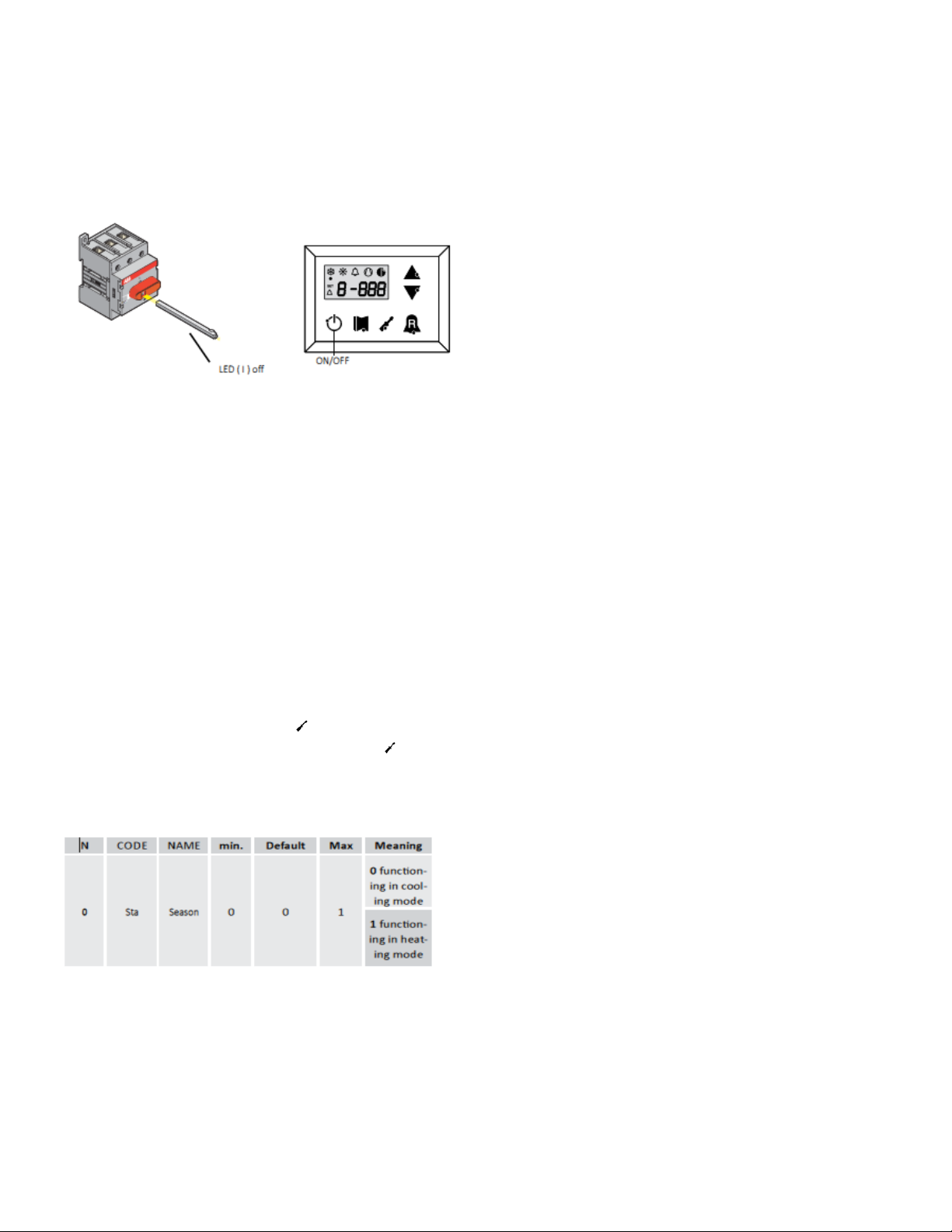
‐PositiontheappliancemasterswitchatON.
‐Makesurethattheauxiliaryswitchcontact(IA)
(seewiringdiagram)isopen(ifused,andthedisplayLED(I)Amustbeoff.
‐PresstheONkeyfor3sectoswitchthemachineon.
4.3. SEASON CHANGEOVER, OPERATION PARAMETERS
‐Foreveryseasonchange,checkthatthefunctioninglimitsliewithinthe
properlimits.
‐Checkthatthecompressorinputcurrentislowerthanthemaximum
indicatedinthetechnicaldatatable.
‐Makesurethatthevoltagevaluelieswithinthepre‐fixedlimitsandthat
unbalancebetweenthethreephases(three‐phasepowersupply)isnot
above3%.
SEASON CHANGEOVER FROM PANEL ON MACHINE
AccesstheUSERSETlistbytouchingtheinsertpasswordkey000
(alreadydisplayed);justconfirmbyre‐pressingthekey
TheparameteraffectedistheSta,changingthevalue0and1willchange
theoperationfromcoolingtoheatingaccordingly.Forfurtherinforma‐
tionrefertotheUSERMANUAL
SEASON CHANGEOVER FROM PR3
Justactdirectlyontheswitch.Themachineswitchesoffautomatically‐
andswitchesback‐onwiththeselectedfunctioningmode.Advancebased
onthetimeframeforthecompletionofworksforthesystem.Priorto
theworktobecarriedoutbytheAERMECservicepersonnel,allother
works(electricalandhydraulichook‐ups,primingandbleedingofair
fromthesystem)musthavebeencompleted.