manuals.online logo
Brands
  1. Home
  2. •
  3. Brands
  4. •
  5. AERMEC
  6. •
  7. Chiller
  8. •
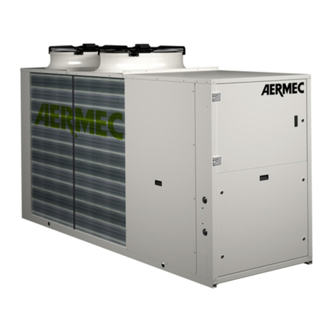
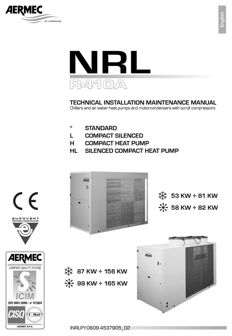
  9. AERMEC AN Installation and operation manual

AERMEC AN Installation and operation manual

This manual suits for next models

19

Other AERMEC Chiller manuals

AERMEC FCX Manual

AERMEC

AERMEC FCX Manual

AERMEC NLC User manual

AERMEC

AERMEC NLC User manual

AERMEC ZX Series User manual

AERMEC

AERMEC ZX Series User manual

AERMEC FCS 22 User manual

AERMEC

AERMEC FCS 22 User manual

AERMEC 1251 Technical document

AERMEC

AERMEC 1251 Technical document

AERMEC WRL 200 User manual

AERMEC

AERMEC WRL 200 User manual

AERMEC Turbocor User manual

AERMEC

AERMEC Turbocor User manual

AERMEC WRL 200 User manual

AERMEC

AERMEC WRL 200 User manual

AERMEC CR Series Installation and operation manual

AERMEC

AERMEC CR Series Installation and operation manual

AERMEC SAF User manual

AERMEC

AERMEC SAF User manual

AERMEC NBW Series Installation and operation manual

AERMEC

AERMEC NBW Series Installation and operation manual

AERMEC NBW 147 Installation and operation manual

AERMEC

AERMEC NBW 147 Installation and operation manual

AERMEC AN R407C Installation and operation manual

AERMEC

AERMEC AN R407C Installation and operation manual

AERMEC NRL 028-075 User manual

AERMEC

AERMEC NRL 028-075 User manual

AERMEC NRL F Series User manual

AERMEC

AERMEC NRL F Series User manual

AERMEC NYB 500 RP Quick start guide

AERMEC

AERMEC NYB 500 RP Quick start guide

AERMEC NXW 0500 User manual

AERMEC

AERMEC NXW 0500 User manual

AERMEC NRB 0800-3600 User manual

AERMEC

AERMEC NRB 0800-3600 User manual

AERMEC Variable Multi Flow ANL Series Manual

AERMEC

AERMEC Variable Multi Flow ANL Series Manual

AERMEC VENICE User manual

AERMEC

AERMEC VENICE User manual

AERMEC NLC 0280 User manual

AERMEC

AERMEC NLC 0280 User manual

AERMEC NRL FC 800 User manual

AERMEC

AERMEC NRL FC 800 User manual

AERMEC ANL User manual

AERMEC

AERMEC ANL User manual

AERMEC NRA F 275 A Installation and operation manual

AERMEC

AERMEC NRA F 275 A Installation and operation manual

Popular Chiller manuals by other brands

Trane RTAA-70 Installation & maintenance guide

Trane

Trane RTAA-70 Installation & maintenance guide

Carrier Omnizone 50BVC Installation, Start-Up, Service and Controls Operation and Troubleshooting

Carrier

Carrier Omnizone 50BVC Installation, Start-Up, Service and Controls Operation and Troubleshooting

York YGWH 115 Installation, commissioning & operation

York

York YGWH 115 Installation, commissioning & operation

Galletti PERFORMA MPE Series Technical manual

Galletti

Galletti PERFORMA MPE Series Technical manual

SMC Networks HRR Series manual

SMC Networks

SMC Networks HRR Series manual

Daikin EWAQ016CAW Installation and operation manual

Daikin

Daikin EWAQ016CAW Installation and operation manual

Trane CVHE Troubleshooting

Trane

Trane CVHE Troubleshooting

Moffat Friginox TSR-11SC Specification sheet

Moffat

Moffat Friginox TSR-11SC Specification sheet

Gree GWH07AGA-K6DNA1C Service manual

Gree

Gree GWH07AGA-K6DNA1C Service manual

MP Systems PURGE Series manual

MP Systems

MP Systems PURGE Series manual

Penguin COLD THERAPY CHILLER owner's manual

Penguin

Penguin COLD THERAPY CHILLER owner's manual

Telemark TVP-2000 Operation, installation and service manual

Telemark

Telemark TVP-2000 Operation, installation and service manual

TICA MINI VRF CHR Series Installation & operation manual

TICA

TICA MINI VRF CHR Series Installation & operation manual

MAXA A68 Installation and operation manual

MAXA

MAXA A68 Installation and operation manual

SABROE ChillPAC operating manual

SABROE

SABROE ChillPAC operating manual

Aqua Optima Corona Instructions for use

Aqua Optima

Aqua Optima Corona Instructions for use

Nordcap SKF 5 GN 1 manual

Nordcap

Nordcap SKF 5 GN 1 manual

lancer Siberian Elite Series Installation, operation & service manual

lancer

lancer Siberian Elite Series Installation, operation & service manual

manuals.online logo
manuals.online logoBrands
  • About & Mission
  • Contact us
  • Privacy Policy
  • Terms and Conditions

Copyright 2025 Manuals.Online. All Rights Reserved.

C
E
R
T
I
F
I
E
D
Q
U
A
L
I
T
Y
S
Y
S
T
E
M
★
H
H
H
H
H
H
H
H
H
H
H
H
H
IANPW
0211
67554.03
Refrigeratori, pompe di calore aria acqua
e motocondensanti
Air to water chillers, heat pumps
and condensing units
AN R22 - R407C
Sostituisce il:
Replace:
67554.02 / 0103
MM
MMAA
AANN
NNUU
UUAA
AALL
LLEE
EE
TT
TTEE
EECC
CCNN
NNII
IICC
CCOO
OO
EE
EE
DD
DD’’
’’II
IINN
NNSS
SSTT
TTAA
AALL
LLLL
LLAA
AAZZ
ZZII
IIOO
OONN
NNEE
EE
TT
TTEE
EECC
CCHH
HHNN
NNII
IICC
CCAA
AALL
LL
AA
AANN
NNDD
DD
II
IINN
NNSS
SSTT
TTAA
AALL
LLLL
LLAA
AATT
TTII
IIOO
OONN
NN
BB
BBOO
OOOO
OOKK
KKLL
LLEE
EETT
TT
3
INFORMAZIONI GENERALI
•
GENERAL INFORMATION
5
CARATTERISTICHE
•
FEATURES
Descrizione dell’unità • Unit description 6
Componenti principali • Main components
Descrizione dei componenti • Component description 8
Organi di regolazione • Controls 10
Organi di sicurezza e controllo • Safety and control devices
Imballo • Packing 11
Accessori • Accessories 12
Tabella di compatibilità degli accessori • Accessories compatibility table 13
Dati tecnici • Technical data 14
Campo di funzionamento • Working range 20
Criteri di scelta • Selection 22
TAV 1-2: Potenza frigorifera totale ed assorbimento elettrico totale
Cooling capacity and total input power 23
TAV 3: Potenza termica totale ed assorbimento elettrico totale
Heating capacity and total input power 25
TAV 4: Livelli di rumorosità • Sound data
TAV 5: Fattore di correzione in raffred. per ∆t diversi da 5 °C • Cooling mode correction factor for
∆
t other than 5 °C
TAV 6: Taratura standard e taratura dei dispositivi di regolazione • Regulation devices standard settings and set range 26
TAV 7: Taratura organi di protezione • Safety devices settings
TAV 8: Fattore di correzione con acqua glicolata • Correction factors for glycol mix 27
TAV 9: Linee frigorifere (AN C) • Refrigerant lines (AN C)
TAV 10: Perdite di carico filtro acqua • Water filter pressure drops 28
TAV 11: Perdite di carico evaporatore• Evaporator pressure drops 29
TAV 12: Prevalenza utile • Available static pressure 30
TAV 13: Contenuto massimo d’acqua dell’impianto • Maximum water content of installation 31
MISURE DI SICUREZZA
•
SAFETY MEASURES
Usi impropri • Improper uses
Simboli di sicurezza • Safety symbol 32
INSTALLAZIONE
•
INSTALLATION
Collegamenti idraulici • Water connections 33
Collegamenti elettrici • Wiring connections 34
Prima della messa in funzione • Before start up
Messa in funzione dell’unità • Unit start up
Caricamento / scaricamento impianto • Filling / draining the installation 35
CARATTERISTICHE
•
FEATURES
Dimensioni • Dimensions 36
Spazi tecnici minimi • Minimum technical space 39
Legenda per schemi frigoriferi • Chiller circuit legend
Lay-out circuito frigorifero e dispositivi di controllo • Lay-out of chiller circuit and control devices 40
Legenda per schemi elettrici • Wiring diagrams key
Dati elettrici • Electrical data 44
Schemi elettrici • Wiring diagrams 45
DICHIARAZIONE DI CONFORMITA'
Noi, firmatari della presente, dichiariamo sotto la nostra esclu-
siva responsabilità che l'insieme in oggetto così definito:
REFRIGERATORE ARIA - ACQUA E POMPA DI CALORE SERIE
AN
risulta :
1. conforme alla Direttiva 97/23/CE ed è stato sottoposto
(grandezze AN da 090 a 150), con riferimento all'allegato II
della direttiva stessa, alla seguente procedura di valutazione
di conformità :
modulo A1
con controlli eseguiti mediante ispezioni dall'organismo
notificato RW-TUV Kurfurstenstrasse 58, D-45138 ESSEN,
numero distintivo 0044;
2. progettato, prodotto e commercializzato nel rispetto delle
seguenti specifiche tecniche (tutti i modelli)
Norme armonizzate:
- EN 378: Refrigerating system and heat pumps - Safety
and environmental requirements;
- EN 12735: Copper and copper alloys - Seamless, round
copper tubes for air conditioning and refrigeration;
Altre norme:
- UNI 1285-68: Calcolo di resistenza dei tubi metallici
soggetti a pressione interna;
3.progettato, prodotto e commercializzato in conformità
alle seguenti direttive comunitarie (tutti i modelli):
- Direttiva macchine 89/392 CEE e modifiche 91/368 CEE,
93/44/CEE e 93/68/CEE;
- Direttiva bassa tensione 73/23 CEE;
- Direttiva compatibilità elettromagnetica EMC 89/336 CEE.
AN C:
È fatto divieto di mettere in servizio la macchina, oggetto
della Dichiarazione, prima che la macchina a cui sarà incorpora-
ta od assiemata sia stata dichiarata conforme alle disposizioni
della Direttiva.
DECLARATION OF CONFORMITY
We declare under our own responsability that the above
equipment described as follows:
AIR TO WATER CHILLER AND HEAT PUMP AN SERIE
complies with following provisions:
1. 97/23/CE Standard , since as per enclosure II, it has
undergone the conformity testing procedure (sizes: AN from
90 to 150):
A1 module
with checks carried out by the appointed body RW-TUV
Kurfurstenstrasse 58, D-45138 ESSEN, identity code 0044;
2. designed, manufactured and commercialized in com-
pliance with the following technical specifications (all
models):
Harmonized standards:
-EN 378: Refrigerating system and heat pumps - Safety
and environmental requirements;
-EN 12735: Copper and copper alloys - Seamless, round
copper tubes for air conditioning and refrigeration;
Others:
-UNI 1285-68: calculation of metal tubes resistance to
inside pressure;
3. designed, manufactured and commercialized in com-
pliance with the following EEC Standards (all models):
- Equipment standard 89/392 EEC and amendments 91/368
CEE, 93/44/CEE and 93/68/CEE;
- Low voltage standard 73/23 EEC;
- Electromagnetic compatibility Standard EMC 89/336 EEC.
AN C: It is not allowed to operate the appliance object of the
Declaration before the appliance it will be incorporated to or
assembled with, is declared in compliance with the provisions of
the Directive.
AN
modello:
model:
numero di serie:
serial number:
AERMEC S.p.A.
I-37040 Bevilacqua (VR) Italia – Via Roma, 44
Tel. (+39) 0442 633111
Telefax 0442 93730 – (+39) 0442 93566
www.aermec.com - [email protected]
Bevilacqua, 02/05/2002 La Direzione Marketing – Marketing Director
Luigi Zucchi
4
5
OSSERVAZIONI
Conservare il manuale in luogo asciutto, per evitare il
deterioramento, per almeno 10 anni per eventuali riferimen-
ti futuri.
Leggere attentamente e completamente tutte le informa-
zioni contenute in questo manuale.
Prestare particolarmente attenzione alle norme d’uso
accompagnate dalle scritte “PERICOLO” o “ATTENZIO-
NE” in quanto, se non osservate, possono causare danno
alla macchina e/o a persone e cose.
Per anomalie non contemplate da questo manuale, interpel-
lare tempestivamente il Servizio Assistenza di zona.
AERMEC S.p.A. declina ogni responsabilità per qualsiasi
danno dovuto ad un uso improprio della macchina, ad una
lettura parziale o superficiale delle informazioni contenute
in questo manuale.
Il numero di pagine di questo manuale è: 68.
REMARKS
Store the manual in a dry location to avoid deterioration, as
they must be kept for at least 10 years for any future reference.
All the information in this manual must be carefully read
and understood.
Pay particular attention to the operating standards with
“DANGER” or “WARNING” signals as their disrespect can
cause damage to the machine and/or persons or objects.
If any malfunctions are not included in this manual, contact
the local Aftersales Service immediately.
AERMEC S.p.A. declines all responsibility for any damage
whatsoever caused by improper use of the machine, and a
partial or superficial acquaintance with the information con-
tained in this manual.
This manual has 68 pages.
6
DESCRIZIONE DELL’UNITÀ
CARATTERISTICHE GENERALI
I refrigeratori e le pompe di calore condensati in aria della
serie AN sono stati progettati e realizzati per soddisfare le
esigenze di raffreddamento e riscaldamento delle medie e
piccole utenze in edifici ad uso residenziale o commerciale.
Disponibili in 9 grandezze, le unità sono caratterizzate da
un funzionamento estremamente silenzioso e da una eleva-
ta efficienza ed affidabilità, grazie all’adozione di scambia-
tori con elevata superficie di scambio e di compressori
scroll di elevate prestazioni e bassa rumorosità.
Sono disponibili in diversi allestimenti per poter soddisfare
una grande varietà di soluzioni impiantistiche: base o con
pompa idraulica e serbatoio d’accumulo acqua integrato.
Sono inoltre disponibili versioni motocondensanti prive
d’evaporatore. Le resistenze elettriche dei compressori sono
di serie per i modelli Solo Freddo e Pompa di Calore a refri-
gerante R407C.
VERSIONI DISPONIBILI
Grandezze disponibili:
AN - 020 - 025 - 030 - 041 - 050 - 080 - 090 - 100 - 150
Combinando opportunamente le numerose opzioni disponibili,
è possibile configurare ciascun modello della serie AN.
La tabella seguente illustra le modalità per la compilazione
della sigla commerciale negli 11 campi che la compongo-
no, rappresentativi delle opzioni disponibili:
Campo 1 e 2 Sigla
AN
Campo 3, 4 e 5 Grandezza
020
025
030
041
050
080
090
100
150
Campo 6 Refrigerante
* R22 (solo modello Pompa di Calore)
7 R407C
Campo 7 Modello
* Solo freddo
H Pompa di calore
Campo 8 Versione
* Standard
A con Accumulo e pompa
Campo 9 Alette batterie
* in alluminio
R in Rame
S in rame Stagnato
Campo 10 Evaporatore
* Standard
C Senza evaporatore (MotoCondensante)
Campo 11 Alimentazione
M 230V-1-50Hz
3 230V-3-50Hz
* 400V-3-50Hz
UNIT DESCRIPTION
MAIN DESCRIPTION
AN chillers and heat pumps have been designed and con-
structed to satisfy small and medium sized cooling and hea-
ting applications in residential or commercial venues.
Available in 9 sizes, the units are characterised by their
silent operation, high efficiency performance and reliability,
thanks to the use of heat exchangers with a large exchange
surface and high-efficiency silent scroll compressors.
The units can be arranged to satisfy a wide range of system
requirements: with base or with integrated pump and stora-
ge tank. Condensing units without evaporator are also avai-
lable.
The electric heaters of compressors are standard for chiller
and heat pump models with refrigerant R407C.
VERSIONS AVAILABLE
Sizes available:
AN - 020 - 025 - 030 - 041 - 050 - 080 - 090 - 100 - 150
Each AN model can be combined with numerous optional
accessories to individual requirements.
The table below shows how the commercial code, made up of
11 fields, is composed. Each field represents an optional com-
ponent:
Field 1 and 2 Code
AN
Field 3, 4 and 5 Size
020
025
030
041
050
080
090
100
150
Field 6 Refrigerant
* R22 (only Heat Pump model)
7 R407C
Field 7 Model
* Cooling only
H Heat pump
Field 8 Version
* Standard
A with storage tank and pump
Field 9 Coil fins
* aluminium
R copper
S tinned copper
Field 10 Evaporator
* Standard
C without evaporator (condensing type)
Field 11 Power supply
M 230V-1-50Hz
3 230V-3-50Hz
* 400V-3-50Hz
7
Esempio:
Si richiede un refrigeratore d’acqua a pompa di calore con
le seguenti caratteristiche:
- Potenza frigorifera resa (alle condizioni nominali di fun-
zionamento): 17,8 kW.
- Potenza termica resa (alle condizioni nominali di funzio-
namento): 18,8 kW.
- Refrigerante: R407C.
- Con accumulo e pompa.
- Batterie di condensazione con alette in alluminio (standard).
- Alimentazione a 230V-3-50Hz.
L’unità rispondente alle suddette caratteristiche tecniche è
identificata dalla seguente sigla commerciale:
AN 080 7 H A * * 3
Come si può aver notato, essendo ogni opzione rappresentata
in maniera univoca da tutte le altre, non è necessario indica-
re, all’interno della sigla commerciale, le opzioni * - standard
(ossia la sigla AN080 7 HA**3 e la sigla AN080 7 HA3 iden-
tificano la stessa unità).
Attenzione:
– Gli AN a pompa di calore (H) prevedono le versioni con:
gas refrigerante R407C (7) ed R22.
– Gli AN motocondensanti (C) sono previsti solo in versione
Standard ad R407C (7).
– Solo gli AN 020 - 025 - 030 - 041 prevedono l’opzione
alimentazione monofase (campo 11: opzione M).
– Solo gli AN 050 - 080 - 090 - 100 - 150 prevedono l’opzione
alimentazione 230V trifase (campo 11: opzione 3).
– Per il funzionamento sotto i 4 °C e fino a - 6 °C occorre
specificare tale esigenza al momento dell’ordine in quanto
l’unità dovrà essere dotata di componenti diversi da quelli
montati sulle macchine Standard.
Example:
A water chiller with heat pump functions with the following
features is required:
- Cooling capacity (at nominal operating conditions): 17,8
kW.
- Heating capacity (at nominal operating conditions): 18,9
kW.
- Refrigerant: R407C .
- Storage tank and pump.
- Condensation coils with aluminium fins (standard).
- Power supply 230V-3-50Hz.
The unit corresponding to the above features is identified by
the following commercial code:
AN 080 7 H A * * 3
As can be noted, given that each component is distinctly
identified, there is no need to specify the * - standard options
(i.e. the codes AN0807HA**3 and AN0807HA3 indicate the
same unit) in the commercial code.
Important:
– AN heat pumps (H) are used with: refrigerant gas R407C
(7) and with R22.
– AN condensing units (C) come in standard versions only
with refrigerant R407C (7).
– AN 020 - 025 - 030 - 041 models can be arranged for
single-phase power (field 11: option M).
– AN 050 - 080 - 090 - 100 - 150 models can be arranged
for single-phase power (field 11: option 3).
– Operating requirements below 4 °C to - 6 °C must be spe-
cified at the time of ordering to allow for installation of
special components on Standard units.
8
DESCRIZIONE DEI COMPONENTI
COMPONENTI CIRCUITO FRIGORIFERO
COMPRESSORE
Di tipo scroll ad elevata efficienza, montato su supporti ela-
stici antivibranti, azionato da un motore elettrico a due poli
con protezione termica interna.
SCAMBIATORE LATO ARIA
Realizzata con tubi di rame ed alette in alluminio bloccate
mediante espansione meccanica dei tubi.È provvisto di gri-
glia di protezione.
SCAMBIATORE LATO ACQUA
Del tipo a piastre, è isolato esternamente con materiale a
celle chiuse per ridurre le dispersioni termiche.
Nelle versioni A dei modelli 020 - 025 - 030 - 041 è posi-
COMPONENT DESCRIPTION
COMPONENTS OF REFRIGERANT CIRCUIT
COMPRESSOR
Scroll, high efficiency type, mounted on anti-vibration pads,
it is driven by a two pole electric motor with inner ampero-
metric protection.
AIR SIDE HEAT EXCHANGER
With copper tubes and aluminum fins locked by mechanical
expansion of the tubes. The heat exchanger is provided with
a protection grill.
WATER SIDE HEAT EXCHANGER
Plate type, externally insulated with closed cell material to
reduce heat losses.
For A versions of 020 - 025 - 030 -041 sizes it’s positioned
24
1
3
5
6
7
8
9
10 11
12
13
314
1Quadro elettrico • Switchboard
2Scambiatore lato aria • Air side exchanger
3Gruppo ventilante • Fan section
4Scambiatore lato acqua • Water side exchanger
5Pressostato di alta • High-pressure switch
6Compressore • Compressor
7Vaso d’espansione • Expansion tank
8Serbatoio d’accumulo • Water storage tank
9Pompa • Pump
10 Pressostato di bassa • Low-pressure switch
11 Valvola termostatica • Thermostatic valve
12 Filtro acqua • Water filter
13 Valvola di sicurezza • Safety valve
14 Pressostato differenziale • Differential pressure switch
COMPONENTI PRINCIPALI • MAIN COMPONENTS
AN0907A
9
zionato all’interno del serbatoio d’accumulo d’acqua.
– FILTRO
R22:
Di tipo meccanico, in grado di trattenere le impurità presen-
ti nel circuito frigorifero.
R407C:
Di tipo meccanico realizzato in ceramica e materiale igro-
scopico, in grado di trattenere le impurità e le eventuali
tracce d’umidità presenti nel circuito frigorifero.
TELAIO E VENTILATORI
MOBILE DI COPERTURA
Realizzato in lamiera di acciaio zincato verniciata a caldo
con polveri poliuretaniche dopo trattamento di passivazio-
ne, è in grado di resistere a lungo all’azione degli agenti
atmosferici.
GRUPPO VENTILANTE
Costituito da uno o due ventilatori elicoidali azionati diret-
tamente da motori elettrici asincroni monofase con prote-
zione termica interna.
È provvisto di griglia di protezione secondo norme CEI EN
60335-2-40.
COMPONENTI ELETTRICI
QUADRO ELETTRICO
Contiene la sezione di potenza e la gestione dei controlli e
delle sicurezze.
SCHEDA ELETTRONICA
Composta da scheda di gestione, controllo e visualizzazio-
ne, consente il controllo completo dell’unità.
COMPONENTI IDRAULICI
VASO D’ESPANSIONE (solo Versioni A )
Del tipo chiuso a membrana, consente la dilatazione
dell’acqua nell’impianto.
SERBATOIO D’ACCUMULO ACQUA (solo Versione A)
Serve per diminuire il numero di spunti del compressore ed
uniformare la temperatura dell’acqua da inviare alle utenze.
POMPA (solo Versioni A)
Consente di far circolare l’acqua nel circuito utenze.
COMPONENTI DI SICUREZZA E CONTROLLO
PRESSOSTATO DI ALTA
A taratura variabile, posto sul lato ad alta pressione del cir-
cuito frigorifero, arresta il funzionamento del compressore
in caso di pressioni anomale di lavoro.
PRESSOSTATO DI BASSA
A taratura fissa, posto sul lato a bassa pressione del circuito
frigorifero, arresta il funzionamento del compressore in caso
di pressioni anomale di lavoro.
VALVOLA DI SICUREZZA ACQUA(solo Versioni A)
Posta sul ramo di mandata del circuito idraulico, interviene
in caso di pressioni eccessive di lavoro.
TERMOSTATO DI ALTA TEMPERATURA (Solo versioni
Pompa di Calore)
A taratura fissa, posto sul lato di alta pressione del circuito
frigorifero, arresta il funzionamento del compressore in caso
di temperature anomale di lavoro.
– PRESSOSTATO DIFFERENZIALE / FLUSSOSTATO
Fornito di serie su tutte le grandezze, è montato tra entrata e
uscita dello scambiatore e, in caso di portata d’acqua trop-
po bassa, ferma il compressore (sia in riscaldamento che in
raffreddamento).
Le versioni A dei modelli 020 - 025 - 030 - 041 sono equi-
paggiate di flussostato posizionato a monte dell’evaporatore.
inside the water tank.
– FILTER
R22:
A mechanical filter, capable of retaining the impurities pre-
sent in the refrigerant circuit.
R407C:
A mechanical filter in ceramic and hygroscopic material,
capable of retaining the impurities and any traces of humi-
dity present in the refrigerant circuit.
FRAME AND FANS
HOUSING
It is made of long life galvanized steel panels hot painted
with polyurethane powder after passivation.
FAN SECTION
It is made of an helicoidal fan directly coupled to an asynch-
ronous, singlephase electric motor with inner thermal pro-
tection.
The fan section is provided with a protection grill according
to CEI standard EN 60335-2-40.
ELECTRICAL COMPONENTS
SWITCHBOARD
It contains the power section and the management of the
controls and safeties.
ELECTRONIC BOARD
Composed of a management, control and display card, it
controls all functions of the unit.
HYDRAULIC COMPONENTS
EXPANSION TANK (only for A Versions)
Diaphragm-type, allows the expansion of water throughout
the system.
WATER STORAGE TANK (only for A Version)
Reduces number of compressor surges and evens water
temperature supplied to utilities.
PUMP (only for A Versions)
Allows water circulation throughout the system.
SAFETY AND CONTROL DEVICES
HIGH-PRESSURE SWITCH
Adjustable setting switch on the high-pressure side of the
cooling circuit, stops the compressor in the event of abnor-
mal operating pressure values.
LOW-PRESSURE SWITCH
Fixed setting switch on the low-pressure side of the cooling
circuit, stops the compressor in the event of abnormal ope-
rating pressure values.
WATER SAFETY VALVE (only for A Versions)
Mail on the branch of sent of the hydraulic circuit, it interve-
nes in case of excessive pressures of job
HIGH-TEMPERATURE SWITCH (Only Heat Pump versions)
Fixed setting switch on the high-pressure side of the cooling
circuit, stops the compressor in the event of abnormal ope-
rating temperature values.
– DIFFERENTIAL PRESSURE SWITCH / FLUXOSTAT
Standard supplied in all model, it is installed between the
water exchanger inlet and outlet and cuts off the compres-
sor (both on heating and cooling modes) in case of poor
water flow rate.
Versions A of models 020 - 025 - 030 - 041 are fitted with
flow switch up-line of the evaporator.
10
ORGANI DI REGOLAZIONE
SCHEDA A MICROPROCESSORE
Composta da scheda di gestione, controllo e visualizzazio-
ne. Funzioni svolte:
• regolazione temperatura acqua ingresso evaporatore.
• ritardo avviamento compressore.
• funzionamento estivo o invernale in pompa di calore
con gestione sbrinamento.
• gestione dispositivo bassa temperatura (accessorio).
• conteggio ore funzionamento compressore.
• conteggio ore funzionamento pompa.
• start/stop.
• reset.
• autostart dopo caduta di tensione.
• funzionamento con possibilità di controllo remoto.
• visualizzazione stato macchina:
ON/OFF compressore;
funzionamento estivo;
funzionamento invernale.
• gestione allarmi:
– alta pressione;
pressostato differenziale acqua / flussostato.
bassa pressione;
antigelo;
sovraccarico compressore.
• visualizzazione dei seguenti parametri:
temperatura ingresso acqua;
temperatura uscita acqua;
temperatura sonda batteria (se presente);
• visualizzazione allarmi.
• impostazioni set:
set caldo;
set freddo;
differenziale freddo;
differenziale caldo.
Ai morsetti 6-12 di M12 è possibile collegare una segnala-
zione esterna di Allarme. Il contatto, normalmente aperto, è
privo di tensione e può comandare un carico da 250 V ~ 1A.
Di seguito sono descritte in dettaglio le principali funzioni
gestite dalla scheda a microprocessore.
– TERMOSTATO DI LAVORO
I grafici riportati di seguito illustrano come viene calcolato il
gradino d’intervento della macchina a seconda dei set di
funzionamento impostati.
CONTROLS
MICROPROCESSOR CARD
Composed of a management, control and display card.
The microprocessor card has the following functions:
• regulation of the evaporator inlet water.
• compressor timing delay.
• summer operation or winter operation as a heat pump
with defrost management.
• management of low temperature control (accessory).
• compressor working hourmeter.
• pump working hourmeter.
• start/stop.
• reset.
• autostart after power failure.
• operation with possibility of remote control.
• machine status display:
compressor ON/OFF;
summer operation;
winter operation.
• alarm management:
– water differential pressure switch / fluxostat.
high pressure;
low pressure;
antifreeze;
compressor overload.
• display of the following parameters:
water inlet temperature;
water outlet temperature;
heat exchanger sensor temperature;
• alarm display.
• set point adjustment:
heating set point;
cooling set point;
cooling differential;
heating differential.
It is possible to connect the teminals 6-12 of M12 with an
external alert signal. The normally-opened contact is without
tension and can control a load of 250 V ~ 1A.
The following is a detailed description of the main functions
managed by the microprocessor.
– OPERATION THERMOSTAT
The diagrams below illustrate the calculations of the inter-
vention step of the machine, on the basis of the set operating
parameters.
r1 TIA
r2
ON
OFF
0%
100%
Po
r3 TIA
r4
ON
OFF
0%
100%
Po
Termostato Freddo ad un gradino
One Step Cooling Thermostat
Termostato Caldo ad un gradino
One Step Heating Thermostat
r1 = Set freddo
r2 = Differenziale in funzionamento a freddo
r3 = Set caldo
r4 = Differenziale in funzionamento a caldo
TIA = Temperatura acqua in ingresso
Po = Potenza resa
r1 = Cooling set point
r2 = Differential in cooling mode
r3 = Heating set point
r4 = Differential in heating mode
TIA = Temperature of Inlet Water
Po = Capacity