manuals.online logo
Brands
  1. Home
  2. •
  3. Brands
  4. •
  5. AERMEC
  6. •
  7. Chiller
  8. •
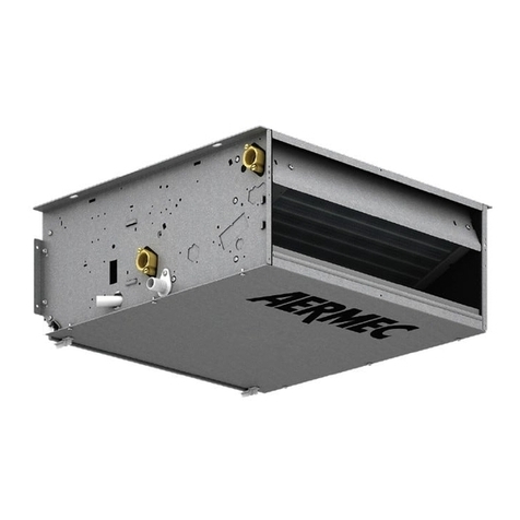
  9. AERMEC FHX User manual

AERMEC FHX User manual

This manual suits for next models

3

Other AERMEC Chiller manuals

AERMEC NLC 0280 User manual

AERMEC

AERMEC NLC 0280 User manual

AERMEC WRL 200 Instruction Manual

AERMEC

AERMEC WRL 200 Instruction Manual

AERMEC NRL FC 800 User manual

AERMEC

AERMEC NRL FC 800 User manual

AERMEC NRL 0280 User manual

AERMEC

AERMEC NRL 0280 User manual

AERMEC NRB Series Manual

AERMEC

AERMEC NRB Series Manual

AERMEC FCS 22 User manual

AERMEC

AERMEC FCS 22 User manual

AERMEC nrl R410A Instruction Manual

AERMEC

AERMEC nrl R410A Instruction Manual

AERMEC NLC User manual

AERMEC

AERMEC NLC User manual

AERMEC NRV 0550 Manual

AERMEC

AERMEC NRV 0550 Manual

AERMEC NRL FC 028 Manual

AERMEC

AERMEC NRL FC 028 Manual

AERMEC NRL User manual

AERMEC

AERMEC NRL User manual

AERMEC 1251 Technical document

AERMEC

AERMEC 1251 Technical document

AERMEC ANL 020 User manual

AERMEC

AERMEC ANL 020 User manual

AERMEC WRL 200 User manual

AERMEC

AERMEC WRL 200 User manual

AERMEC Turbocor User manual

AERMEC

AERMEC Turbocor User manual

AERMEC NRA F 275 A Installation and operation manual

AERMEC

AERMEC NRA F 275 A Installation and operation manual

AERMEC NRB 0800 Manual

AERMEC

AERMEC NRB 0800 Manual

AERMEC NRL 028-075 User manual

AERMEC

AERMEC NRL 028-075 User manual

AERMEC NBW 147 Installation and operation manual

AERMEC

AERMEC NBW 147 Installation and operation manual

AERMEC NYB User manual

AERMEC

AERMEC NYB User manual

AERMEC NRL2000A User manual

AERMEC

AERMEC NRL2000A User manual

AERMEC NRB 0800-3600 User manual

AERMEC

AERMEC NRB 0800-3600 User manual

AERMEC FCX Manual

AERMEC

AERMEC FCX Manual

AERMEC NRL FC 2000 User manual

AERMEC

AERMEC NRL FC 2000 User manual

Popular Chiller manuals by other brands

Trane RTAA-70 Installation & maintenance guide

Trane

Trane RTAA-70 Installation & maintenance guide

Carrier Omnizone 50BVC Installation, Start-Up, Service and Controls Operation and Troubleshooting

Carrier

Carrier Omnizone 50BVC Installation, Start-Up, Service and Controls Operation and Troubleshooting

York YGWH 115 Installation, commissioning & operation

York

York YGWH 115 Installation, commissioning & operation

Galletti PERFORMA MPE Series Technical manual

Galletti

Galletti PERFORMA MPE Series Technical manual

SMC Networks HRR Series manual

SMC Networks

SMC Networks HRR Series manual

Daikin EWAQ016CAW Installation and operation manual

Daikin

Daikin EWAQ016CAW Installation and operation manual

Trane CVHE Troubleshooting

Trane

Trane CVHE Troubleshooting

Moffat Friginox TSR-11SC Specification sheet

Moffat

Moffat Friginox TSR-11SC Specification sheet

Gree GWH07AGA-K6DNA1C Service manual

Gree

Gree GWH07AGA-K6DNA1C Service manual

MP Systems PURGE Series manual

MP Systems

MP Systems PURGE Series manual

Penguin COLD THERAPY CHILLER owner's manual

Penguin

Penguin COLD THERAPY CHILLER owner's manual

Telemark TVP-2000 Operation, installation and service manual

Telemark

Telemark TVP-2000 Operation, installation and service manual

TICA MINI VRF CHR Series Installation & operation manual

TICA

TICA MINI VRF CHR Series Installation & operation manual

MAXA A68 Installation and operation manual

MAXA

MAXA A68 Installation and operation manual

SABROE ChillPAC operating manual

SABROE

SABROE ChillPAC operating manual

Aqua Optima Corona Instructions for use

Aqua Optima

Aqua Optima Corona Instructions for use

Nordcap SKF 5 GN 1 manual

Nordcap

Nordcap SKF 5 GN 1 manual

lancer Siberian Elite Series Installation, operation & service manual

lancer

lancer Siberian Elite Series Installation, operation & service manual

manuals.online logo
manuals.online logoBrands
  • About & Mission
  • Contact us
  • Privacy Policy
  • Terms and Conditions

Copyright 2025 Manuals.Online. All Rights Reserved.

FHX
TECHNICAL MANUAL
IFHXTY
0809
4267320_00
ISO 9001 - Cert. n° 0128/4
Replace: 5266420_00 / 0705
FAN COIL WITH GERMICIDAL LAMP
UV
UVP
UVPO
FHX
3
English
4
5
6
7
8
9
10
11
15
16
22
23
24
25
26
27
29
30
39
40
40
41
42
43
43
45
DECLARATION OF CONFORMITY
Carriage • Safety symbol
Important information
Description • Versions
Main components• Component description
Selection
System configuration
Technical data
Operating limits
Delivery cooling capacity
Heating power input (3R)
Heating power input ( (4R)
Hanging version available static pressure
Battery pressure drop
Correction factors in functioning with glycoled water
Sound power and sound pressure
Sound power level for ducted wall/ceiling-mounting models
Accessories
Unit installation
Electrical connections
Replacing the lamps
Dip-Switch
Rotating the coil
Technical areas
Dimensions
Wiring diagram
INDEX
Store the manuals in a dry location to avoid deterioration, as
they must be kept for at least 10 years for any future reference.
All the information in this manual must be carefully read and
understood. Pay particular attention to the operating stan-
dards with “DANGER” or “WARNING” signals as failure to
comply with them can cause damage to the machine and/or
persons or objects.
If any malfunctions are not included in this manual, contact
the local After-sales Service immediately.
The apparatus must be installed in such a way that maintenan-
ce and/or repair operations are possible.
The apparatus's warranty does not in any case cover costs due
to automatic ladders, scaffolding or other lifting systems neces-
sary for carrying out repairs under guarantee.
Normal wear of components and filter is not covered by the
warranty.
AERMEC S.p.A. declines all responsibility for any damage
whatsoever
caused by improper use of the machine, and a partial or super-
ficial acquaintance with the information contained in this
manual.
The number of pages in this manual is: 48.
REMARKS
5
1
2
3
4
5
6
35Kg
NON bagnare • Do NOT wet
CRAINT l’humidité • Vor Nässe schützen
NO mojar
NON lasciare gli imballi sciolti durante il trasporto.
Do NOT leave loose packages during transport.
ATTACHER les emballages pendant le transport.
Die Verpackungen nicht ungesichert transportieren.
NO lleve las cajas sueltas durante el transporte.
Sovrapponibilità: controllare sull’imballo la posizione della freccia per
conoscere il numero di macchine impilabili.
Stacking: control the packing for the arrow position to know the num-
ber of machines that can be stacked.
Empilement: vérifier sur l’emballage la position de la flèche pour con-
naître le nombre d’appareils pouvant être empilés.
Stapelung: Anhand der Position des Pfeiles an der Verpackung kontrol-
lieren, wieviele Geräte stapelbar sind.
Apilamiento: observe en el embalaje la posición de la flecha para saber
cuántos equipos pueden apilarse.
NON calpestare • Do NOT trample
NE PAS marcher sur cet emballage • Nicht betreten
NO pisar
NON trasportare la macchina da soli se il suo peso supera i 35 Kg.
DO NOT handle the machine alone if its weight is over 35 Kg.
NE PAS transporter tout seul l’appareil si son poids dépasse 35 Kg.
Das Gerät NICHT alleine tragen, wenn sein Gewicht 35 Kg überschreitet.
NO maneje los equipos en solitario si pesan más de 35 kg.
Pericolo: Pericolo: Pericolo!!!
Tensione Organi in movimento
Danger: Danger: Danger!!!
Power supply Movings parts
Danger: Danger: Danger!!!
Tension Organes en mouvement
Gefahr ! Gefahr ! Gefahr!!!
Spannung Rotierende Teile
Peligro: Peligro: Peligro!!!
Tensión Elementos en movimiento
TRASPORTO • CARRIAGE • TRANSPORT • TRANSPORT • TRANSPORTE
SIMBOLI DI SICUREZZA • SAFETY SYMBOL • SIMBOLES DE SECURITE
SICHERHEITSSYMBOLE • SÍMBOLOS DE SEGURIDAD
6
English
The fan coils are shipped in standard packaging which consists of expanded polystyrene foam and cardboard shells.
PACKAGING
IMPORTANT INFORMATION AND MAINTENANCE
Consult the control panel manual for operating instructions.
USE
WARNING: the electrical wirings, the
installation of the fan coils and their
accessories, maintenance and the yearly
replacement of the germicidal lamps
must be performed only by a techni-
cian who has the necessary technical
and professional qualifications to install,
modify, extend and service the systems
and who is capable of assessing these
systems for the purposes of safety and
functionality.
WARNING: before carrying out any
work, wear the proper personal protec-
tive equipment.
WARNING: the fan coil is connected to
the power supply and a water circuit.
Any operation by persons who do not
possess the required technical skills can
lead to personal injury to the operator
or damage to the unit and surrounding
objects.
WARNING: The appliance must be fit-
ted according to the national regulation
on process plant engineering.
WARNING: Check that the power sup-
ply is disconnected before carrying out
any procedures on the unit.
WARNING: Install a device, main switch
or plug which makes it possible to com-
pletely cut off the power supply from
the unit.
DANGER! The UVC radiation emitted
by the germicidal lamp is dangerous
and may cause conjunctivitis, burns and
erythema.
It is absolutely prohibited to operate the
device with the germicidal lamp when it
has been removed from the fan coil.
It is absolutely prohibited to operate
the device with the germicidal lamp if
the fan coil has not been adequately
installed.
WARNING! DANGER! Any use of the
unit not expressly indicated by Aermec
is strictly prohibited.
MALFUNCTIONS
In the event of a malfunction, cut off
power supply to the unit, then restore
the power and start the unit again.
If the problem occurs again, contact
your After Sales Service department
immediately.
ONLY POWER THE FAN COIL AT
230 VAC 50 HZ
Any other type of power supply could
permanently damage the fan coil.
DO NOT USE THE FAN COIL IMPROP-
ERLY
Do not use the fan coil in animal hus-
bandry applications (e.g. incubation).
AIRING THE ROOM
Periodically air the room in which the
fan coil has been installed. This is partic-
ularly important if the room is occupied
by many people, or if gas appliances or
sources of odours are present.
DURING OPERATION
Always leave the filter fitted on the fan
coil during operation (otherwise dust in
the air could soil the coil surface area).
CORRECT TEMPERATURE ADJUST-
MENT
The room temperature should be regulat-
ed in order to provide maximum comfort
to the people in the room, especially if
they are elderly, children or ill; avoiding
temperature differences of more than 7°C
between outside and inside the room in
summer.
In summer, a temperature that is too low
causes higher electrical consumption.
CORRECT AIR JET AIMING ADJUST-
MENT
The air coming out of the fan coil must
not impact directly on people; in fact,
even if temperature is higher than the
room temperature, it could cause a cold
sensation resulting in discomfort.
DO NOT USE EXCESSIVELY HOT
WATER
Clean the fan coil with a soft cloth or
sponge soaked in water not over 40 °C.
Do not use chemical products or sol-
vents to clean any part of the fan coil.
Do not spray water on the outer or inner
surfaces of the fan coil (it might cause
short circuits).
CLEAN THE FILTER FREQUENTLY
Before performing any maintenance pro-
cedures requiring access to the internal
parts of the fan coil, cut off the power
supply in order to avoid being exposed
to the light emitted by the lamp.
Cleaning the filter frequently guarantees
enhanced operating efficiency.
Check whether the filter is very dirty: if it
is, clean it more often.
Clean frequently; remove the accumu-
lated dust with a vacuum cleaner.
Once the filter is clean, refit it to the fan
coil following the removal instructions
but in reverse order.
SUPPLEMENTARY CLEANING
Before performing any maintenance pro-
cedures requiring access to the internal
parts of the fan coil, cut off the power
supply in order to avoid being exposed
to the light emitted by the lamp.
The fact that the blades of inspectable
shrouds can be removed (operation done
only by adequately skilled technicians)
ensures a thorough cleaning of the inter-
nal components, which is particularly
important when installing the unit in
crowded areas or venues requiring high
hygiene standards.
WHAT IS NORMAL
In the cooling function, water vapour
may be present in the air delivery of the
fan coil.
In the heating function, a slight hiss
might be heard close to the fan coil.
Sometimes the fan coil might give off
unpleasant smells due to the accumula-
tion of substances present in the air of
the environment (clean the filter more
often especially if the room is not venti-
lated regularly).
During the operation, there could be
noises and creaks inside the device, due
to the various thermal expansions of the
elements (plastic and metallic), but this
does not indicate any malfunction and
does not damage the unit unless the
maximum input water temperature is
exceeded.
REPLACING THE LAMPS
This procedure may only be performed
by people with the necessary specific
technical skills.
Before performing any maintenance pro-
cedures requiring access to the internal
parts of the fan coil, cut off the power
supply in order to avoid being exposed
to the light emitted by the lamp.
Never let yourself come into direct con-
tact with the light produced by the lamp,
as the UVC radiation may cause serious
eye and skin irritation.
Lamps should be replaced every year
in order to ensure that the germicidal
action remains constant.
7
English
FHX - FAN COIL WITH GERMICIDAL LAMP
The FHX fan coil concentrates high technological and func-
tional characteristics that make it the ideal climate control unit
for all types of rooms. The supply of climate-controlled air is
immediate and distributed throughout the room. FHX gener-
ates heat if included in a heating system with boiler or heat
pump, but may also be used in summer as an air conditioner if
the heating system has a water chiller.
The FHX fan coil is fitted with an exclusive device featuring
a mercury-vapour germicidal lamp for air sterilisation, offer-
ing anti-microbiological action which is 99.999% effective in
combating all Gram - and Gram + microorganisms. The germi-
cidal lamp, positioned in the air delivery flow, cleans the coil
more thoroughly and prevents the formation of mould on the
surface of the fins, thereby ensuring the unit operates at its
maximum efficiency level in the long term, while reducing the
need for coil cleaning procedures.
The fact that the tray and the fan shrouds can be inspected
means you can carefully clean the internal parts as well.
These characteristics make the FHX unit indispensable in ven-
ues requiring high hygiene standards, such as:
• hospitals
• dentists' surgeries
• doctors' and vets' consulting rooms
• clynical analysis laboratories
• pharmaceutical companies
• waiting rooms
• beauty salons
• homes
• offices
• public premises
The new centrifugal fan unit is so quiet that at a normal oper-
ating speed you cannot hear when the FHX cuts in.
All models in the FHX range are supplied without a control
panel.
The PXAI and PXAE combinable control panels are supplied as
accessories; they activate the germicidal lamp operation as well
as the ventilation function, and are fitted with an electronic ther-
mostat which controls fan coil operation in order to maintain the
set temperature in the room. They also make electronic tempera-
ture adjustment and manual/automatic fan speed adjustment
possible, while the heating or cooling operating mode is selected
automatically (change of season) and depends on the temperature
of the water circulating inside the system.
The PXAI control panel may be fitted underneath the flap to the
right of the FHX_UV fan coil.
The PXAE control panel to be wall-mounted may be used com-
bined with all versions of the FHX range.
The fan coils in the FHX range are designed to satisfy all
system requirements, thanks to the wide range of accessories
available.
Full compliance with accident prevention regulations.
Congratulations on your purchase of this Aermec FHX fan coil.
Made with materials of superior quality in strict compliance with safety regulations, "FHX" is easy to use and will
have a long life.
VERSIONS
FHX_UV: with a 3-row coil, a
3-speed motor, universal cabinet for
vertical and horizontal installation
and anti-corrosive polyester powder
coated finish, RAL 9002. The air de-
livery and suction louvers are made
of plastic material, RAL 7044.
The control panel may be fitted on
board the unit (PXAI accessory) or
externally (PXAE accessory).
FHX_UVP: with 3- or 4-row
coils, version without casing, with
a 3-speed motor, for horizontal and
vertical wall installation, requires
external control panel (PXAE acces-
sory).
FHX_UVPO: with 3- or 4-row
coils, version without casing, with
a boosted motor set to operate at 7
speeds (3 of which may be selected),
for horizontal and vertical ceiling
installation, requires external con-
trol panel (PXAE accessory).
FHX UVP - UVPO
FHX 22 ÷ 50 UV FHX 62 - 82 UV
Available in 3 versions and 6 sizes with a 3-row coil and, only for ducted versions, in 6 sizes with a 4-row coil:
FHX 22 - 24
FHX 32 - 34
FHX 42 - 44
FHX 50 - 54
FHX 62 - 64
FHX 82 - 84
8
English
MAIN COMPONENTS
HEAT EXCHANGE COIL
Coil with copper pipe and alumini-
um fins held in place by means of the
mechanical expansion of the pipes. The
manifolds are fitted with female connec-
tions and air vents in the upper part of
the coil.
FILTRATION SECTION
Easily removable and made from regen-
erable materials. May be cleaned by
washing.
P and PO versions are equipped with G2
class filter.
CABINET
Casing in RAL9002
Air delivery and suction louvers in
RAL7044
Made from specially treated, polyester
powder-coated sheet metal to ensure
superior rust and corrosion resistance.
UV Version : at the upper part, there are
the louver (it is orientable and can be
closed again for sizes 22; 32; 42 and 50;
flat and fixed for sizes 62 and 82), made
from thermoplastic material to distribute
air, and the door to access the control
panel. With the orientable louver fully
closed, the tripping of the microswitch
stops ventilation, thus interrupting any
further heat exchange with the environ-
ment.
The casing also features a ther-
moplastic air recirculation louver at the
front.
ELECTRIC FAN ASSEMBLY
It consists of double suction radial fans
with lengthways blades to obtain a high
air flow with a low number of revs. The
electrical motor, protected against over-
loading, has three speeds with the run-
ning capacitor always on, directly cou-
pled with the fans and cushioned with
flexible supports. The FHX UVPO ver-
sion is equipped with a boosted motor
set to operate at 7 speeds (3 of which
may be selected).
BEARING STRUCTURE
Made of galvanised sheet metal of an
adequate thickness. Hole in the back
for wall mounting. A fan cover panel is
available for front-mounted ceiling units.
Each unit is equipped with a condensate
collection tray.
CONDENSATE DRAIN
Every device is fitted with a tray for col-
lecting condensation, with a connection
for draining condensation produced by
the unit in cooling mode.
PLUMBING CONNECTIONS
The connections, located on the left
hand side, are female. The coil may also
be rotated.
GERMICIDAL LAMP
Germicidal lamp that emits UVC rays.
This lamp has a one-year life span; after
that time, it should be replaced with a
similar lamp. The lamp serves to prevent
mould from forming in the fan coil, to
eliminate microbiological contamination
and to avoid its spread into the room.
The UVC radiation emitted by the lamp
destroys the main cellular DNA and
RNA.
The immediate effect is that cells cannot
reproduce and are killed; therefore, the
risk of airborne-transmitted infections is
reduced up to 90%.
Germicidal lamps emitting UVC rays
installed in the fan coils can prevent:
- TB conversions within healthcare facili-
ties.
- Legionnaire's disease.
- Microorganisms in the discharge cir-
cuits.
- Contaminated filters or overpressure.
- Spread of infections.
DESCRIPTION OF COMPONENTS
1Heat exchange coil
2Air filter
3Protective cabinet (RAL9002)
4Fan motor
5Fan
6Load-bearing structure
7Condensate drain
8Plumbing connections
9Head with orientable fins (RAL7044)
10Germicidal lamp
FHX 42 UV
1
9
8
7
6
5
4
3
2
10
9
English
SELECTION CRITERIA
Models with universal cabinet (UV) fea-
ture a front intake and can be mounted
either vertically on a wall or horizon-
tally on the ceiling.
Wall/ceiling-mounting (UVP and UVPO)
versions, without protective cabinet
and with intake at the bottom, can be
installed either vertically or horizontally.
In case of ducted installations where
pressure drops in the ducts are consid-
erable, the UVPO model (with boosted
multi-speed motors) enables to have the
effective pressure needed to guarantee a
correct air flow rate.
The UVP and UVPO models are avail-
able with 3- and 4-row coils.
The UV model has to be combined with
a control panel to be installed internally
or externally. Consult the characteristics
and compatibility of the control panels
supplied as accessories.
The UVP and UVPO models have to be
combined with a control panel to be
installed externally. Consult the charac-
teristics and compatibility of the control
panels supplied as accessories.
The control panels can control a net-
work of fan coils if they are used in
combination with the interface cards
SIT3 and SIT5 supplied as accessories.
The main technical data of the FHX
range are summarised in the tables.
The total and sensible cooling capacities
yielded at maximum speed according to
the temperature and thermal head of
the incoming water, the air temperature
with dry bulb or wet bulb for sensible
yield and total yield respectively for
models with a 3-row coil are shown
in the table. Performances at medium
and minimum speeds can be obtained
by multiplying the values in the table
by the correction factors indicated; for
4-row coil models, by multiplying the
values in the table by the correction fac-
tors indicated for each speed.
Pressure drops on the water side for 3-
and 4-row coils respectively are shown
in the graphs.
The correction factors when the unit
operates with glycol water for cooling
and heating function modes are shown
in the graphs in percentages of glycol of
10%, 20% and 35%.
The heating capacity yielded by the 3-
and 4-row coils according to the water
flow rate and the difference in tem-
perature between the incoming water
and the incoming air is represented in
a graph and it refers to the maximum
speed. Performances at medium and
minimum speeds can be obtained by
multiplying the values obtained from
the graph at maximum speed by the
correction factors indicated.
For the ducted wall/ceiling-mounting
models (UVP and UVPO), the perform-
ances described before must be con-
sidered as referring to air flow rates
equal to those corresponding to the
(UV) models at maximum speed (rated
capacities).
The pressure for the wall/ceiling-mount-
ing models according to the air flow
rate and the fan speed are shown as
a table; the curves show each speed.
For scaling the ducted wall/ceiling-
mounting models, it is advisable to pro-
ceed as follows: choose the size that
given a normal flow rate has a power
immediately above that required; after-
wards, mark out the curve of the duct
pressure drops on the rate-pressure dia-
gram related to the machine in ques-
tion in order to individualise the points
of machine operation at the different
speeds. Based on the capacity values
of these points, you will obtain the cor-
rection factors that help calculate the
capacity yielded given the actual condi-
tions of air flow rate. For multi-speed
models, this procedure helps to suitable
choose the speeds to be set.
The pressure and sound power levels
of fan coils at the different speeds are
shown in separated tables for 3- and
4-row coils models. For the ducted wall/
ceiling models, the sound power level
is expressed according to the air flow
rate and pressure, and represented as
graphs.
There is a wide range of accessories for
FHX fan coils, sometimes some of them
cannot be used at the same time; check
that the accessories are compatible with
the fan coil chosen. The manual shows
the description of each accessory plus a
drawing and its compatibility.
The installation information is includ-
ed in the manuals supplied together
with each fan coil or its accessory. This
manual is limited to provide general
information in order to obtain a correct
installation; it also contains drawings
with fan coil dimensions and the wiring
diagrams with the connections to con-
trol panels.
10
English
SW
AIR
SW
AIR
SW
AIR
SA
SA
230V 230V 230V
UVGI UVGI
SA
UVGI
VCF VCF
AIR AIR AIR
SA
SA
230V 230V 230V
UVGI UVGI
SA
UVGI
VCF VCF
SW Water temperature sensor
VCF Solenoid valve (Heating / Cooling) SA Room temperature sensor
V3,V2,V1 Maximum, Medium or Minimum fan speed
SYSTEM CONFIGURATIONS FOR FHX FAN COILS
System with 2 pipes, without water sensor
Key:
System with 2 pipes, with water sensor
11
English
TECHNICAL DATA
Performance values refer to the following conditions:
Sound pressure measured in semi-reverberating chamber, 85m3,
and with reverberation time Tr = 0.5s.
Cooling:
- room air temperature 27°C D.B., 19°C W.B.;
• maximum speed:
- water inlet temperature 7°C; ∆t water 5°C.
• medium and minimum speed:
- water inlet temperature 7°C;
- water flow rate as at maximum speed.
Heating:
room air temperature 20°C D.B.;
• maximum speed:
- water inlet temperature 70°C; ∆t water 10°C.
• medium and minimum speed:
- water inlet temperature 70°C;
- water flow rate as at maximum speed.
• maximum speed (water inlet 50°C):
- water inlet temperature 50°C;
- water flow rate as for cooling operation.
Mod.
Heating
W (max.)
Heating capacity W (med.)
W (min.)
Heating capacity * W(E)
(water inlet 50°C)
Water flow rate l/h
Water pressure drops kPa
Cooling
W (max.) (E)
Total cooling capacity W (med.)
W (min.)
W (max.) (E)
Sensible cooling capacity W (med.)
W (min.)
Water flow rate l/h
Water pressure drops kPa (E)
m
3/h (max.)
Air flow rate m3/h (med.)
m
3/h (min.)
Number of fans
dB (A) (max.)
Sound pressure dB (A) (med.)
dB (A) (min.)
dB (A) (max.) (E)
Sound power dB (A) (med.) (E)
dB (A) (min.) (E)
Water content l
Max. motor power W (E)
Max. input current A
3R Coil connections ø
1R Coil connections ø
FHX UV - UVP with a 3-row coil
Electrical power supply = 230V ~ 50Hz (E) = EUROVENT certified performances
FHX 22 FHX 32 FHX 42 FHX 50 FHX 62 FHX 82
3400 4975 7400 8620 12920 15140
2700 4085 6415 7530 10940 13350
1915 3380 5115 5420 8330 10770
2100 3160 4240 4900 6460 7990
292 427 636 741 1110 1300
6,3 14,2 14,1 14,2 14,8 19,8
1500 2210 3400 4190 4860 7420
1330 2055 2800 3640 4660 5500
1055 1570 2310 2840 3950 4710
1240 1750 2760 3000 3980 5680
1055 1540 2115 2750 3510 4250
755 1100 1635 2040 2825 3450
258 380 585 721 836 1276
5,8 16,6 14,3 19,3 11,6 13,5
290 450 600 720 920 1140
220 350 460 600 720 930
140 260 330 400 520 700
1 2 2 2 3 3
41,5 39,5 42,5 47,5 48,5 53,5
34,5 32,5 35,5 42,5 42,5 48,5
22,5 25,5 28,5 33,5 33,5 41,5
50 48 51 56 57 62
43 41 44 51 51 57
31 34 37 42 42 50
0,79 1,11 1,48 1,48 2,52 2,52
50 69 82 92 182 206
0,24 0,33 0,4 0,47 0,84 0,93
1/2” 1/2” 3/4” 3/4” 3/4” 3/4”
1/2” 1/2” 1/2” 1/2” 1/2” 1/2”