AERMEC NRB 0800 Manual

BARCODE
EN
Installation and Maintenance Manual
TRANSLATION FROM ORIGINAL
• OUTDOOR INSTALLATION
• MICROCHANNEL COIL
• NIGHT MODE NRB
0800÷3000
18.10 4138468_01
60Hz


Dear customer,
Thank you for choosing an AERMEC product. It is the fruit of many years of experience
and special design studies and has been made of the highest grade materials and with
cutting edge technology.
The quality level is being constantly monitored, so AERMEC products are synonymous
with Safety, Quality and Reliability.
The data may undergo modifications considered necessary for the improvement
of the product, at any time and without the obligation for any notice thereof.
Thank you once again.
AERMEC S.p.A

INDEX
GENERAL WARNINGS....................................................................................................................................................6
RECEPTION........................................................................................................................................................................8
LIFTING ..............................................................................................................................................................................8
STORAGE............................................................................................................................................................................9
DIMENSIONS .................................................................................................................................................................10
MINIMUM TECHNICAL SPACES ..............................................................................................................................12
WEIGHT DISTRIBUTION.............................................................................................................................................15
HYDRAULIC CONNECTIONS....................................................................................................................................18
WATER FEATURES ........................................................................................................................................................18
HYDRAULIC DIAGRAMS ...........................................................................................................................................19
ELECTRICAL CONNECTIONS ...................................................................................................................................20
ELECTRIC POWER CONNECTION TO THE ELECTRICAL MAINS.................................................................. 21
ELECTRICAL DATA .......................................................................................................................................................22
ACCESSORIES ................................................................................................................................................................27
COMPATIBILITY OF ACCESSORIES ........................................................................................................................27
COMMISSIONING WARNINGS..............................................................................................................................28
MAINTENANCE.............................................................................................................................................................29
MAINTENANCE LIST OF THE RECOMMENDED PERIODIC INTERVENTIONS...................................... 32


6
GENERAL WARNINGS
Warning;
Biological hazard
Electricity
Wear head
protection
Wear ear protection
Wear eye protection
Warning;
Sharp element
Wear protective
gloves
Wear safety
footwear
Warning;Warning; Warning;
Moving parts Flammable material
Warning;
Hot surface
GENERAL WARNINGS
This product is a complex machine. Things and persons may be exposed
to risks during installation, operation, maintenance or repair, caused
by certain conditions or components, such as for example, but not
only, refrigerant, oils, moving mechanical parts pressure, heat sources,
electricity.
This products and its documentation, including this manual, are intended
for persons in possession of appropriate training to enable them to
operate correctly and safely. Before performing any operation on this
equipment, it is essential for the operating personnel to have read and
understood all manuals and any other material of reference. They must
also know and observe the standards applicable to the activities to be
performed.
ATTENTION
Any intervention on the unit must be performed by authorised
and qualied experienced technicians, in accordance with current
regulations.
The unit shows the following risks:
• Risk of electric discharges.
• Risk of injuries due to rotating parts.
• Risk of injuries due to sharp edges and heavy weights.
• Risk of injuries due to high pressure gas.
• Risk of injuries due to high or low temperatures of components.
• Substances inside the water;
• Fire risk.
• In the event of the refrigerant catching re, hazardous gases may be
generated.
It is vital that all work on the unit is performed in compliance with the
local standards. All work on the system must be performed to perfection
preCautions against resiDual risKs
instruCtions
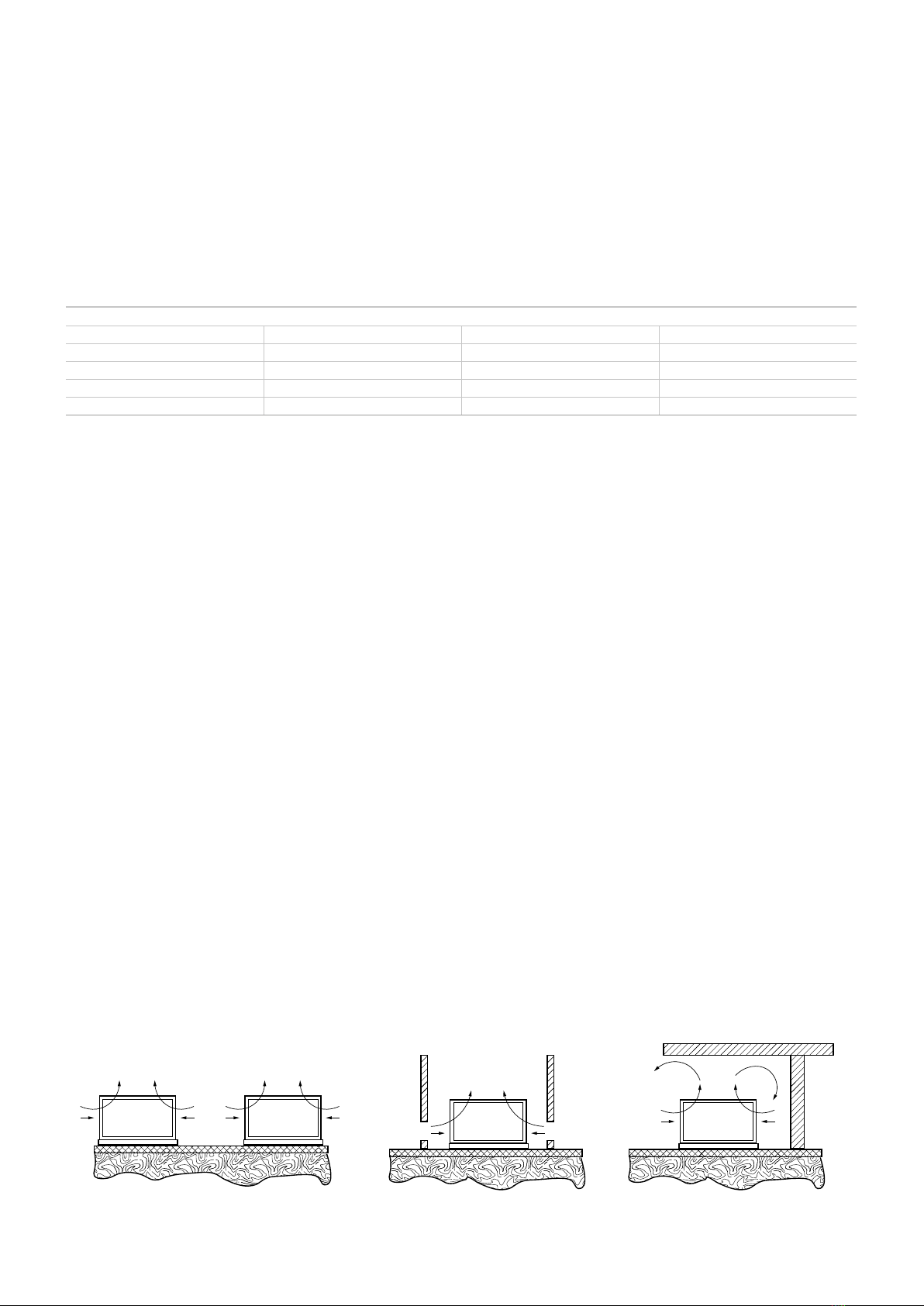
- Install the unit according to the requirements herein
- The personnel nearing the machine must be competent in the
use of this refrigerant and observe the current regulations.
- Personnel that come into contact with the machine must be
competent in the use of this refrigerant and respect regulations
currently in force. Assess the procedures Aermec requires and
local re prevention regulations to prevent inconsistencies in our
requirements and regulations currently in force.
- Regularly perform all maintenance operations provided for in this
manual
- Wear personal protective equipment (gloves, eye protection,
helmet, …) appropriate to the operations to be performed; do not
wear clothes or accessories that may get caught or be sucked by the
air ows; gather and tie your hair up before entering the unit
- The machine must be transported in compliance with current
regulations, taking into account the features of the uids inside and
their characterisation described in the safety data sheet
- An inadequate transport may damage the machine, also generating
refrigerant leaks. Before commissioning, check for leaks and make any
necessary repairs.
- The installation must comply with the requirements of EN378-3 and
the local current regulations. In particular, indoor installation must
ensure adequate ventilation and provide refrigerant detectors when
necessary.
- The machine must not be installed in environments with risk of
explosion but in a suitable place. In particular, if intended for indoor
use, it cannot be installed outdoors
- The machines must be installed in structures protected from lightning
as provided by the applicable laws and technical standards
- The overall re risk assessment at the place of installation (i.e. re load
calculation) is the responsibility of the user.
- Keep re extinguishers near the machine suitable for putting out
res on electrical equipment and, for lubricant oil of the compressor
and the refrigerant as provided by the relative safety data sheets (for
example a CO2re extinguisher)
- It is not permitted to walk or place other bodies on the machines
- Make the plant engineering connections to the unit according to the
instructions in this manual
- It is mandatory to install a water lter on the evaporator, penalty
invalidation of the warranty
- Do not bend or hit pipes containing under pressure uids
Do not exceed the maximum allowable pressure (PS) of the unit’s
water circuit shown on the serial number plate
- Before removing elements along the under pressure water circuits,
shut-o the pipe section involved and gradually drain the uid until
its pressure and that of the atmosphere are balanced.
- The unit contains under pressure refrigerant gas: no operation
must be performed on under pressure equipment except during
maintenance that must be carried out by competent and authorised
personnel
- Perform brazing or welding only on empty pipes and clear of any
lubricating oil residues; do not near ames or other heat sources to
the pipes containing refrigerant uid
- Do not work with naked ames near the unit
- In order to avoid an environmental risk, make sure that any uid leaks
are recovered in suitable devices in compliance with local regulations.
- Do not use your hands to control any refrigerant leaks
- An accidental release of refrigerant may cause risk of suocation
due to a lack of oxygen: install the machine in a well ventilated
environment in accordance with EN 378-3 and local regulations
currently in force. Those who come into contact with the machine
must be equipped with a leak detector that is calibrated and
validated to reveal any used refrigerant leaks.
- The unit is tted out with overpressure relief devices (safety valves):
in the event that these devices start, the refrigerant gas is released at
high temperature and high velocity.
Prevent the gas ow from harming people or things; if necessary,
channel the leak according to the EN 378-3 standard and local
regulations currently in force, paying particular attention to channel

7
uids that pertain to safety groups other than A1 toward open and
secure spaces.
- Keep all lubricants in properly marked containers do not keep
ammable liquids near the plant
- Do not remove the protections from mobile elements while the unit
is running
- Do not use cables with inadequate section or ying connections, not
even for limited periods or emergencies
- Check the unit is properly earthed before starting it
- Before opening the electrical panel, disconnect the unit from the
mains by means of the external isolator
- In case of units with shunt capacitors, wait 3 minutes from when
power supply was disconnected from the unit before accessing inside
the electrical panel
- If the unit is equipped with integrated inverter compressors,
disconnect the power supply and wait at least 15 minutes before
accessing for maintenance: the internal components remain live for
this time, generating the risk of electrocution
- The safety devices must be maintained ecient and periodically
checked as prescribed by current regulations
- In case a piece is disassembled, make sure it is correctly reassembled
before restarting the unit
- Even with the unit o, prevent the uid in contact with the
heat exchangers exceed the temperature limits indicated in the
documentation and freeze.
- Do not send the heat exchangers uids other than water or its
mixtures with ethylene glycol/propylene in a maximum concentration
of 30%
- The machine must only be employed for the use for which it was
made; any other use can be dangerous and void the warranty
- Install the unit at a distance enough from the exhaust wells, to ensure
that the possible loss of gas may reach and pollute the aquifer
preVentions
- Make sure that the protections of mobile elements are correctly in
place before restarting the unit
- Fans, motors and belt drives may be in motion: always wait for them
to stop and take appropriate precautions to prevent their activation
before accessing them
- the machine and the pipes have very hot and very cold surfaces that
lead to risk of burns
- Before opening a machine panel, ascertain whether it is or not rmly
connected to it by hinges
- Louvers of the heat exchangers, edges of the components and metal
panels can generate cuts
- The installation must ensure that the temperature of the uid
entering the unit is maintained stable and within the provided limits;
therefore, pay attention to the adjustment of any external thermal
exchange and control devices (drycooler, evaporating towers,
area valves, ...), to the adequate dimensioning of the mass of uid
circulating in the plant (in particular when plant areas are excluded)
and to install systems for the recirculation of the necessary uid ow
rate so as to maintain the machine temperatures within the allowed
limits (e.g. during the start-up phase).
- The material used for the machine protective packaging must always
be kept out of the reach of children as it is a source of danger
- In units with compressors in parallel, do not disable the individual
compressors for long periods.
- This appliance can be used by children aged from 8 years and above
and persons with reduced physical, sensory or mental capabilities or
lack of experience and necessary knowledge if they are supervised
or have received instructions concerning use of the appliance in a
safe way and understand the hazards involved. Children should not
play with the appliance. Cleaning and maintenance intended to be
performed by the user should not be performed by children without
supervision.

8
RECEPTION
CAUTION
ALWAYS USE
ALL THE UNIT
LIFTING EYEBOLTS
PROVIDED
RXXXX
DISEGNO SPECIFICO DEL MODELLO-
SOLLEVAMENTO UNITÀ CON CINGHIE,
CORDE O FUNI
Packaging label
Technical plate
RECEPTION
transport anD HanDling
The unit must be handled by qualied personnel. Carefully follow the
lifting instructions on the labels placed on the unit.
The unit must be lifted with extreme care to prevent knocks to the frame,
panels, electrical panel, etc..
NOTE: Plastic elements can be used to protect the units against damage
during transport. The machine is also wrapped in packaging. We recom-
mend keeping this protection during all transport and lifting operations
and not remove the plastic elements until commissioning.
If the unit has anti-vibration supports, they must be installed on the unit
before nal positioning.
Inspection upon receipt
Perform the following check upon receipt of the product.
- Check that the exterior has not been damaged in any way.
- Check that the lifting and transport devices are appropriate to the
type of equipment and compliant with the transport and handling
instructions attached to this manual.
- Check that the accessories required for on-site installation have been
delivered and are operational.
- If the unit is provided pre-loaded with refrigerant, make sure there have
been no leaks.
- Check that the equipment supplied corresponds to the order and
delivery note
Product identication
The Aermec products can be identied by the packaging label bearing
the identication data of the product and by the technical plate bearing
the performance and technical data of your unit.
If the product is damaged, send a registered letter with the details of
the problem to the shipping company within 48 working hours from
delivery.
lifting
Before lifting the unit, place protections between the belts (or ropes and
chains) and the framework to prevent damage to the structure.
CAUTION: ALWAYS USE ALL THE UNIT LIFTING POINTS PROVIDED
• Follow all safety regulations and standards
• Wear safety glasses, work gloves and safety shoes
• Pay the utmost attention to heavy and bulky equipment during lifting
and handling, and when placing it on the ground.
• All panels must be tightly xed before moving the unit
• Before lifting, check the specic weight on the technical plate.
• Use all, and only, the lifting points indicated;
• Use ropes in compliance with Standards and of equal length;
• Use a spacer in accordance with the sling (not included) see drawing
• Handle the unit with care and without sudden movements
• Do not stand under the unit during lifting
Attention: the units cannot be stacked
lifting
Before lifting the unit, place protections between the belts and the fra-
mework to prevent damage to the structure.
The units NRB are delivered with lifting eyebolts, for lifting use suitable straps,
hook the lifting chains to the eyebolts provided.
• Follow all safety regulations and standards
• Wear protective goggles and work gloves
• Pay the utmost attention to heavy and bulky equipment during lifting
and handling, and when placing it on the ground.
• All panels must be tightly xed before moving the unit;
• Before lifting, check the specic weight on the technical plate.
• Use all, and only, the lifting points indicated;
• Use ropes in compliance with Standards and of equal length;
• Handle the unit with care and without sudden movements
• Do not stand under the unit during lifting
• The machine must be kept in a vertical position
Attention: the units cannot be stacked
Example layout
Packging label
Technical plate
Motor data plate

9
STORAGE
It may happen that, after receipt, the units are not to be immediately installed and are kept in storage. In case of medium-long term storage, we recom-
mend applying the following procedures:
• Make sure there is no water inside the hydraulic systems.
• Do not remove the protections from the heat exchanger.
• Do not remove the plastic protective lms.
• Make sure that the electrical panels are closed.
• Before using the equipment, store all items provided in a dry and clean place so that they can be used in the future. We recommend storing the unit in a
dry and sheltered place (especially for units intended for indoors).
NOTE The maximum storage temperature of the units depends on the type of refrigerant contained, see table. Beyond this limit, there is a risk of refrigerant
leaking through the safety valves.
plaCement anD installation reQuirements
For unit installation it is important to perform the following preliminary
preparation tasks:
• When installing, make sure that the atmospheric or environmental agents
do not aect and corrode the cooling circuit components, causing the
refrigerant to leak in the environment and, if so, make the appropriate
adjustments.
• The air-cooled units with fans are designed for outdoor installation.
Contact Aermec before making any type of installation.
• The water-cooled units are designed for indoor installation. Contact
Aermec before making any type of installation.
• For the positioning of the air-cooled units for outdoor use, choose a place
that is not exposed to excessive wind (install windbreaks if the wind speed
exceeds 86.6in/s).
• The soil under the unit must be at, smooth and suciently strong to
withstand the weight of the unit with a full refrigerant load, as well as the
occasional presence of the normal maintenance equipment.
• In locations exposed to frost, if the unit is installed on soil, the support
base must rest on concrete columns with a depth greater than the normal
depth of frost of the soil. It is always advisable to build a support base
separate from the main building to avoid the transmission of vibrations.
• For normal applications, the rigidity of the unit and the positioning of
point loads allow for an installation that minimises vibrations. In the case
of installations requiring particularly low vibration levels, you can use the
anti-vibration supports.
ATTENTION: The use of anti-vibration supports MUST be combined with
the installation in the unit water piping of exible couplings. The anti-
vibration supports must be xed to the unit BEFORE it is earthed. AERMEC
is not responsible for the choice of capacity of the anti-vibration supports.
• The unit must be xed to the anti-vibration supports and these rmly
xed to the concrete base, see chapter weight distribution and minimum
technical spaces
• Check that the contact surfaces of the anti-vibration supports are levelled
to the base. If necessary, use spacers or level the base but, in any case,
make sure that the anti-vibration supports rest at on the base surface.
• It is essential that the units are installed leaving sucient space around
them to allow easy access to the components for maintenance and repair
purposes.
ATTENTION: It is important that the units are installed at. The improper
installation of the unit invalidates the warranty.
Recommended Installation Windbreak
recommended with wind above 86.6 in/s
Installation not allowed
Recommended 90.6in
Maximum storage temperature
Refrigerant Type Class Max. Temp. (°F)
R134a HFC A1 <122 °F
R410A HFC A1 <122 °F
R1234ze HFO A2L <122 °F
R513A <122 °F
STORAGE

10
DIMENSIONS
NRB 1800 3000
C
A
B

11
Unit Vers. V-blok Fan A (00, PA-DH, AA-BH) B (00, PA-DH, AA-BH) C (00, PA-DH, AA-BH)
NRB n° n° in in in
0800 A 2497 87 110 (*)
0900 A 2497 87 110 (*)
1000 A 3697 87 156
1100 A 3697 87 156
1200 A 3697 87 156
1400 A 3697 87 156
1600 A 4897 87 203
1800 A 4897 87 203
2000 A 510 97 87 250
2200 A 510 97 87 250
2400 A 612 97 87 297
2600 A 714 97 87 344
2800 A 714 97 87 344
3000 A 714 97 87 344
0800 E 3697 87 156
0900 E 3697 87 156
1000 E 3697 87 156
1100 E 4897 87 203
1200 E 4897 87 203
1400 E 4897 87 203
1600 E 510 97 87 250
1800 E 612 97 87 297
2000 E 612 97 87 297
2200 E 714 97 87 344
2400 E 714 97 87 344
2600 E 816 97 87 391
2800 E 816 97 87 391
3000 E 918 97 87 438
0800 U 3697 87 156
0900 U 3697 87 156
1000 U 3697 87 156
1100 U 4897 87 203
1200 U 4897 87 203
1400 U 4897 87 203
1600 U 510 97 87 250
1800 U 612 97 87 297
2000 U 612 97 87 297
2200 U 714 97 87 344
2400 U 714 97 87 344
2600 U 816 97 87 391
2800 U 816 97 87 391
3000 U 918 97 87 438
0800 N 4897 87 203
0900 N 4897 87 203
1000 N 4897 87 203
1100 N 510 97 87 250
1200 N 510 97 87 250
1400 N 510 97 87 250
1600 N 612 97 87 297
1800 N 714 97 87 344
2000 N 714 97 87 344
2200 N 816 97 87 391
2400 N 816 97 87 391
2600 N 918 97 87 438
2800 N 918 97 87 438
3000 N 10 20 97 87 469
DIMENSIONS
(*) The versions equipped with hydronic kit change length AA-BH dimension from 110 in to 156 in.

12
MINIMUM TECHNICAL SPACES
D
B
C
A
E
F
L
E
F
A
B C
D
* Minimum technical space, to be ensured in order for the chiller to work properly and for possible maintenance.
ATTENTION with this space, the condenser coil can only be pulled out from above; to pull it out from the side you must
leave at least 91 in.
2
1
Panel type
Fin 41,8
Fin 39
Electric power
board
NRB 3000 N
1000 / 1150 mm
3000 mm
2300 mm
3000 mm
118 in
118 in
91 in
39/45 in
Electric power
board

13
MINIMUM TECHNICAL SPACES
* Minimum technical space, to be ensured in order for the chiller to work properly and for possible maintenance. ATTENTION: with this space, the condenser coil can
only be pulled out from above, see gures on the next page; to pull it out from the side you must leave at least 91 in.
Unit Vers. V-blok Fans Panel type A B C D E
NRB n° n° mm mm mm mm mm
800 A 2 4 1 39* 43 39* 32 118
900 A 2 4 1 39* 43 39* 32 118
1000 A 3 6 1 39* 43 39* 32 118
1100 A 3 6 1 39* 43 39* 32 118
1200 A 3 6 1 39* 43 39* 32 118
1400 A 3 6 1 39* 43 39* 32 118
1600 A 4 8 1 45* 43 45* 32 118
1800 A 4 8 1 45* 43 45* 32 118
2000 A 5 10 1 45* 43 45* 32 118
2200 A 5 10 1 45* 43 45* 32 118
2400 A 6 12 1 45* 43 45* 32 118
2600 A 7 14 1 45* 43 45* 32 118
2800 A 7 14 1 58* 43 58* 32 118
3000 A 7 14 1 58* 43 58* 32 118
800 E 4 8 1 39* 43 39* 32 118
900 E 4 8 1 39* 43 39* 32 118
1000 E 5 10 1 39* 43 39* 32 118
1100 E 6 12 1 45* 43 45* 32 118
1200 E 6 12 1 45* 43 45* 32 118
1400 E 7 14 1 45* 43 45* 32 118
1600 E 7 14 1 45* 43 45* 32 118
1800 E 8 16 1 45* 43 45* 32 118
2000 E 8 16 1 45* 43 45* 32 118
2200 E 8 18 1 45* 43 45* 32 118
2400 E 10 20 1 45* 43 45* 32 118
2600 E 10 20 1 45* 43 45* 32 118
2800 E 10 20 1 58* 43 58* 32 118
3000 E 9 18 1 58* 43 58* 32 118
800 U 48 1 39* 43 39* 32 118
900 U 48 1 39* 43 39* 32 118
1000 U 510 1 39* 43 39* 32 118
1100 U 612 1 45* 43 45* 32 118
1200 U 612 1 45* 43 45* 32 118
1400 U 714 1 45* 43 45* 32 118
1600 U 714 1 45* 43 45* 32 118
1800 U 816 1 45* 43 45* 32 118
2000 U 816 1 45* 43 45* 32 118
2200 U 918 1 45* 43 45* 32 118
2400 U 10 20 1 45* 43 45* 32 118
2600 U 10 20 1 45* 43 45* 32 118
2800 U 10 20 1 58* 43 58* 32 118
3000 U 918 1 58* 43 58* 32 118
800 N 510 1 45* 43 45* 32 118
900 N 510 1 45* 43 45* 32 118
1000 N 612 1 45* 43 45* 32 118
1100 N 714 1 45* 43 45* 32 118
1200 N 714 1 45* 43 45* 32 118
1400 N 816 1 45* 43 45* 32 118
1600 N 816 1 45* 43 45* 32 118
1800 N 918 1 45* 43 45* 32 118
2000 N 918 1 45* 43 45* 32 118
2200 N 10 20 1 45* 43 45* 32 118
2400 N 11 22 1 45* 43 45* 32 118
2600 N 11 22 1 45* 43 45* 32 118
2800 N 11 22 1 58* 43 58* 32 118
3000 N 10 20 2 58* 32 58* 32 118

14

15
WEIGHT DISTRIBUTION
Upper view
Upper view - NRB 3000 N
1 3 5 7 9 11 13 15 17 19 21
1 3 5 7 9 11 13 15 17 19 21
Evaporator side
Evaporator side
Compressors side
Compressors side
Compressors side
Compressors side
x
x
y
y
2 4 6 8 10 12 14 16 18 20 22
2 4 6 8 10 12 14 16 18 20 22

16
WEIGHT DISTRIBUTION
Model Size Versions
WEIGHT
Empty
BARYCENTRE WEIGHT
Working
BARYCENTRE Weight distribution % on the support
(Based on the weight in operation)
Model Size Versions
Weight distribution % on the support
(Based on the weight in operation)
Anti-vibration
mounts
XG1 YG1 XG1 YG1 1 2 3 4 5 6 7 8 9 10 11 12 13 14 15 16 17 18 19 20 21 22
lbs [in] [in] lbs [in] [in] % % % % % % % % % % % % % % % % % % % % % %
NRB 0800 A 4762 55 48 4806 55 48 11,5% 14,2% 33,2% 41,1% - - - - NRB 0800 A - - - - - - - - - - - - - - AVX1099
NRB 0800 E 5776 82 50 5831 82 50 13,8% 18,7% 0,0% 0,0% 28,7% 38,9% - - NRB 0800 E - - - - - - - - - - - - - - AVX1080
NRB 0800 U 5776 82 50 5831 82 50 13,8% 18,7% 0,0% 0,0% 28,7% 38,9% - - NRB 0800 U -------------- AVX1080
NRB 0800 N 6856 102 47 6911 102 47 12,8% 15,0% 11,1% 13,0% 0,0% 0,0% 22,1% 26,0% NRB 0800 N -------------- AVX1081
NRB 0900 A 5159 54 49 5214 54 49 12,4% 16,0% 31,2% 40,4% - - - - NRB 0900 A - - - - - - - - - - - - - - AVX1099
NRB 0900 E 6107 81 51 6162 81 51 14,0% 19,8% 0,0% 0,0% 27,4% 38,8% - - NRB 0900 E - - - - - - - - - - - - - - AVX1080
NRB 0900 U 6107 81 51 6162 81 51 14,0% 19,8% 0,0% 0,0% 27,4% 38,8% - - NRB 0900 U - - - - - - - - - - - - - - AVX1080
NRB 0900 N 7187 102 48 7242 102 48 12,7% 15,5% 10,7% 13,2% 0,0% 0,0% 21,5% 26,4% NRB 0900 N - - - - - - - - - - - - - - AVX1081
NRB 1000 A 6437 81 52 6493 81 52 14,1% 20,8% 0,0% 0,0% 26,3% 38,8% - - NRB 1000 A - - - - - - - - - - - - - - AVX1080
NRB 1000 E 6504 81 52 6581 81 52 14,2% 20,9% 0,0% 0,0% 26,3% 38,7% - - NRB 1000 E -------------- AVX1080
NRB 1000 U 6504 81 52 6581 81 52 14,2% 20,9% 0,0% 0,0% 26,3% 38,7% - - NRB 1000 U - - - - - - - - - - - - - - AVX1080
NRB 1000 N 7562 101 48 7639 101 48 12,6% 16,0% 10,6% 13,4% 0,0% 0,0% 20,9% 26,5% NRB 1000 N - - - - - - - - - - - - - - AVX1081
NRB 1100 A 6570 81 52 6647 80 52 14,2% 21,1% 0,0% 0,0% 26,0% 38,7% - - NRB 1100 A - - - - - - - - - - - - - - AVX1080
NRB 1100 E 7650 102 49 7727 101 48 13,8% 17,7% 7,1% 9,1% 0,0% 0,0% 22,8% 29,4% NRB 1100 E - - - - - - - - - - - - - - AVX1081
NRB 1100 U 7650 102 49 7727 101 48 13,8% 17,7% 7,1% 9,1% 0,0% 0,0% 22,8% 29,4% NRB 1100 U - - - - - - - - - - - - - - AVX1081
NRB 1100 N 8510 123 48 8587 122 48 11,3% 14,2% 8,1% 10,2% 0,0% 0,0% 14,1% 17,7% NRB 1100 N 10,9% 13,6% - - - - - - - - - - - - AVX1083
NRB 1200 A 6658 81 52 6735 80 52 14,2% 21,3% 0,0% 0,0% 25,8% 38,7% - - NRB 1200 A - - - - - - - - - - - - - - AVX1080
NRB 1200 E 7871 101 49 7981 100 48 14,0% 17,8% 7,7% 9,8% 0,0% 0,0% 22,4% 28,4% NRB 1200 E - - - - - - - - - - - - - - AVX1081
NRB 1200 U 7871 101 49 7981 100 48 14,0% 17,8% 7,7% 9,8% 0,0% 0,0% 22,4% 28,4% NRB 1200 U - - - - - - - - - - - - - - AVX1081
NRB 1200 N 8730 122 48 8841 121 48 11,3% 14,0% 8,7% 10,7% 0,0% 0,0% 14,0% 17,4% NRB 1200 N 10,7% 13,3% - - - - - - - - - - - - AVX1083
NRB 1400 A 6900 80 52 7011 80 52 14,5% 21,7% 0,0% 0,0% 25,5% 38,3% - - NRB 1400 A -------------- AVX1080
NRB 1400 E 7959 100 49 8069 100 48 13,9% 17,9% 7,7% 9,8% 0,0% 0,0% 22,2% 28,5% NRB 1400 E -------------- AVX1081
NRB 1400 U 7959 100 49 8069 100 48 13,9% 17,9% 7,7% 9,8% 0,0% 0,0% 22,2% 28,5% NRB 1400 U -------------- AVX1081
NRB 1400 N 8818 121 48 8929 121 48 11,3% 14,1% 8,6% 10,7% 0,0% 0,0% 14,0% 17,5% NRB 1400 N 10,6% 13,2% - - - - - - - - - - - - AVX1083
NRB 1600 A 8047 100 49 8157 100 49 13,9% 18,0% 7,6% 9,9% 0,0% 0,0% 22,0% 28,5% NRB 1600 A -------------- AVX1081
NRB 1600 E 9039 121 48 9171 120 48 12,7% 15,8% 6,7% 8,4% 0,0% 0,0% 13,7% 17,0% NRB 1600 E 14,3% 11,5% - - - - - - - - - - - - AVX1083
NRB 1600 U 9039 121 48 9171 120 48 12,7% 15,8% 6,7% 8,4% 0,0% 0,0% 13,7% 17,0% NRB 1600 U 14,3% 11,5% - - - - - - - - - - - - AVX1083
NRB 1600 N 9811 147 48 9943 146 47 7,6% 9,3% 10,3% 12,6% 0,0% 0,0% 13,6% 16,6% NRB 1600 N 0,0% 0,0% 13,5% 16,5% - - - - - - - - - - AVX1084
NRB 1800 A 8223 100 49 8356 99 48 14,0% 18,0% 7,9% 10,2% 0,0% 0,0% 21,9% 28,1% NRB 1800 A -------------- AVX1081
NRB 1800 E 9899 147 48 10031 146 47 8,0% 9,8% 9,8% 12,1% 0,0% 0,0% 12,2% 15,0% NRB 1800 E 0,0% 0,0% 14,9% 18,3% - - - - - - - - - - AVX1084
NRB 1800 U 9899 147 48 10031 146 47 8,0% 9,8% 9,8% 12,1% 0,0% 0,0% 12,2% 15,0% NRB 1800 U 0,0% 0,0% 14,9% 18,3% - - - - - - - - - - AVX1084
NRB 1800 N 10869 162 47 11001 161 47 10,7% 12,9% 3,5% 4,2% 7,3% 8,8% 0,0% 0,0% NRB 1800 N 13,8% 16,6% 0,0% 0,0% 10,1% 12,1% - - - - - - - - AVX1085
NRB 2000 A 9171 121 48 9304 120 48 12,4% 15,6% 6,7% 8,4% 0,0% 0,0% 13,9% 17,4% NRB 2000 A 14,2% 11,3% - - - - - - - - - - - - AVX1083
NRB 2000 E 10031 146 48 10196 144 47 8,4% 10,3% 9,9% 12,1% 0,0% 0,0% 11,9% 14,6% NRB 2000 E 0,0% 0,0% 14,8% 18,0% - - - - - - - - - - AVX1084
NRB 2000 U 10031 146 48 10196 144 47 8,4% 10,3% 9,9% 12,1% 0,0% 0,0% 11,9% 14,6% NRB 2000 U 0,0% 0,0% 14,8% 18,0% - - - - - - - - - - AVX1084
NRB 2000 N 11001 161 47 11166 160 47 10,6% 12,7% 3,8% 4,5% 7,4% 8,9% 0,0% 0,0% NRB 2000 N 13,7% 16,4% 0,0% 0,0% 10,0% 12,0% - - - - - - - - AVX1085
NRB 2200 A 9789 126 49 9954 126 49 10,6% 13,2% 8,3% 10,4% 0,0% 0,0% 12,6% 15,7% NRB 2200 A 16,3% 13,0% - - - - - - - - - - - - AVX1100
NRB 2200 E 11883 166 48 12136 164 47 8,3% 10,1% 8,0% 9,8% 3,4% 4,2% 0,0% 0,0% NRB 2200 E 14,7% 17,9% 0,0% 0,0% 10,6% 13,0% - - - - - - - - AVX1087
NRB 2200 U 11883 166 48 12136 164 47 8,3% 10,1% 8,0% 9,8% 3,4% 4,2% 0,0% 0,0% NRB 2200 U 14,7% 17,9% 0,0% 0,0% 10,6% 13,0% - - - - - - - - AVX1087
NRB 2200 N 12743 198 47 12996 196 47 5,1% 6,2% 2,9% 3,4% 11,7% 14,0% 0,0% 0,0% NRB 2200 N 8,7% 10,4% 0,0% 0,0% 11,6% 13,9% 5,5% 6,6% - - - - - - AVX1101
NRB 2400 A 11111 146 50 11277 145 49 9,8% 13,1% 8,3% 11,1% 0,0% 0,0% 9,4% 12,5% NRB 2400 A 0,0% 0,0% 15,4% 20,5% - - - - - - - - - - AVX1089
NRB 2400 E 12434 160 48 12688 158 48 8,8% 11,1% 9,4% 11,9% 2,8% 3,6% 0,0% 0,0% NRB 2400 E 13,4% 17,0% 0,0% 0,0% 9,8% 12,4% - - - - - - - - AVX1087
NRB 2400 U 12434 160 48 12688 158 48 8,8% 11,1% 9,4% 11,9% 2,8% 3,6% 0,0% 0,0% NRB 2400 U 13,4% 17,0% 0,0% 0,0% 9,8% 12,4% - - - - - - - - AVX1087
NRB 2400 N 13294 173 48 13547 171 48 6,0% 7,5% 10,4% 13,0% 4,3% 5,4% 0,0% 0,0% NRB 2400 N 11,8% 14,7% 0,0% 0,0% 8,2% 10,3% 3,8% 4,7% - - - - - - AVX1090
NRB 2600 A 12522 159 48 12776 157 48 9,6% 12,1% 9,1% 11,5% 2,4% 3,0% 0,0% 0,0% NRB 2600 A 13,4% 17,0% 0,0% 0,0% 9,7% 12,3% - - - - - - - - AVX1087
NRB 2600 E 13448 193 48 13702 191 48 4,1% 5,1% 4,0% 5,0% 13,0% 16,2% 0,0% 0,0% NRB 2600 E 6,5% 8,1% 0,0% 0,0% 11,8% 14,7% 5,1% 6,4% - - - - - - AVX1091
NRB 2600 U 13448 193 48 13702 191 48 4,1% 5,1% 4,0% 5,0% 13,0% 16,2% 0,0% 0,0% NRB 2600 U 6,5% 8,1% 0,0% 0,0% 11,8% 14,7% 5,1% 6,4% - - - - - - AVX1091
NRB 2600 N 14286 215 48 14539 213 47 4,5% 5,6% 2,9% 3,6% 12,5% 15,4% 0,0% 0,0% NRB 2600 N 5,1% 6,3% 0,0% 0,0% 11,6% 14,3% 0,0% 0,0% 8,2% 10,0% - - - - AVX1092
NRB 2800 A 12588 159 48 12842 157 48 9,6% 12,2% 9,1% 11,5% 2,3% 2,9% 0,0% 0,0% NRB 2800 A 13,4% 17,0% 0,0% 0,0% 9,7% 12,3% - - - - - - - - AVX1087
NRB 2800 E 13514 193 48 13768 191 48 4,1% 5,1% 4,0% 5,0% 13,0% 16,2% 0,0% 0,0% NRB 2800 E 6,5% 8,1% 0,0% 0,0% 11,8% 14,7% 5,1% 6,4% - - - - - - AVX1091
NRB 2800 U 13514 193 48 13768 191 48 4,1% 5,1% 4,0% 5,0% 13,0% 16,2% 0,0% 0,0% NRB 2800 U 6,5% 8,1% 0,0% 0,0% 11,8% 14,7% 5,1% 6,4% - - - - - - AVX1091
NRB 2800 N 14352 215 48 14606 214 47 4,5% 5,6% 2,9% 3,6% 12,5% 15,4% 0,0% 0,0% NRB 2800 N 5,1% 6,3% 0,0% 0,0% 11,6% 14,3% 0,0% 0,0% 8,2% 10,0% - - - - AVX1092
NRB 3000 A 12787 158 48 13084 156 48 9,5% 11,9% 9,7% 12,1% 2,2% 2,8% 0,0% 0,0% NRB 3000 A 13,3% 16,8% 0,0% 0,0% 9,6% 12,0% - - - - - - - - AVX1087
NRB 3000 E 14551 214 48 14848 213 47 4,1% 5,0% 2,7% 3,3% 14,7% 17,9% 0,0% 0,0% NRB 3000 E 3,0% 3,7% 0,0% 0,0% 12,0% 14,6% 0,0% 0,0% 8,6% 10,5% - - - - AVX1092
NRB 3000 U 14551 214 48 14848 213 47 4,1% 5,0% 2,7% 3,3% 14,7% 17,9% 0,0% 0,0% NRB 3000 U 3,0% 3,7% 0,0% 0,0% 12,0% 14,6% 0,0% 0,0% 8,6% 10,5% - - - - AVX1092
NRB 3000 N 15234 225 49 15532 224 49 3,4% 4,5% -1,2% -1,5% 13,5% 17,7% 0,0% 0,0% NRB 3000 N 11,0% 14,5% 0,0% 0,0% 6,0% 7,9% 0,0% 0,0% 8,9% 11,6% 1,6% 2,1% - - AVX1093

17
Model Size Versions
WEIGHT
Empty
BARYCENTRE WEIGHT
Working
BARYCENTRE Weight distribution % on the support
(Based on the weight in operation)
Model Size Versions
Weight distribution % on the support
(Based on the weight in operation)
Anti-vibration
mounts
XG1 YG1 XG1 YG1 1 2 3 4 5 6 7 8 9 10 11 12 13 14 15 16 17 18 19 20 21 22
lbs [in] [in] lbs [in] [in] % % % % % % % % % % % % % % % % % % % % % %
NRB 0800 A 4762 55 48 4806 55 48 11,5% 14,2% 33,2% 41,1% - - - - NRB 0800 A - - - - - - - - - - - - - - AVX1099
NRB 0800 E 5776 82 50 5831 82 50 13,8% 18,7% 0,0% 0,0% 28,7% 38,9% - - NRB 0800 E - - - - - - - - - - - - - - AVX1080
NRB 0800 U 5776 82 50 5831 82 50 13,8% 18,7% 0,0% 0,0% 28,7% 38,9% - - NRB 0800 U - - - - - - - - - - - - - - AVX1080
NRB 0800 N 6856 102 47 6911 102 47 12,8% 15,0% 11,1% 13,0% 0,0% 0,0% 22,1% 26,0% NRB 0800 N - - - - - - - - - - - - - - AVX1081
NRB 0900 A 5159 54 49 5214 54 49 12,4% 16,0% 31,2% 40,4% - - - - NRB 0900 A - - - - - - - - - - - - - - AVX1099
NRB 0900 E 6107 81 51 6162 81 51 14,0% 19,8% 0,0% 0,0% 27,4% 38,8% - - NRB 0900 E - - - - - - - - - - - - - - AVX1080
NRB 0900 U 6107 81 51 6162 81 51 14,0% 19,8% 0,0% 0,0% 27,4% 38,8% - - NRB 0900 U - - - - - - - - - - - - - - AVX1080
NRB 0900 N 7187 102 48 7242 102 48 12,7% 15,5% 10,7% 13,2% 0,0% 0,0% 21,5% 26,4% NRB 0900 N - - - - - - - - - - - - - - AVX1081
NRB 1000 A 6437 81 52 6493 81 52 14,1% 20,8% 0,0% 0,0% 26,3% 38,8% - - NRB 1000 A - - - - - - - - - - - - - - AVX1080
NRB 1000 E 6504 81 52 6581 81 52 14,2% 20,9% 0,0% 0,0% 26,3% 38,7% - - NRB 1000 E - - - - - - - - - - - - - - AVX1080
NRB 1000 U 6504 81 52 6581 81 52 14,2% 20,9% 0,0% 0,0% 26,3% 38,7% - - NRB 1000 U - - - - - - - - - - - - - - AVX1080
NRB 1000 N 7562 101 48 7639 101 48 12,6% 16,0% 10,6% 13,4% 0,0% 0,0% 20,9% 26,5% NRB 1000 N - - - - - - - - - - - - - - AVX1081
NRB 1100 A 6570 81 52 6647 80 52 14,2% 21,1% 0,0% 0,0% 26,0% 38,7% - - NRB 1100 A - - - - - - - - - - - - - - AVX1080
NRB 1100 E 7650 102 49 7727 101 48 13,8% 17,7% 7,1% 9,1% 0,0% 0,0% 22,8% 29,4% NRB 1100 E - - - - - - - - - - - - - - AVX1081
NRB 1100 U 7650 102 49 7727 101 48 13,8% 17,7% 7,1% 9,1% 0,0% 0,0% 22,8% 29,4% NRB 1100 U - - - - - - - - - - - - - - AVX1081
NRB 1100 N 8510 123 48 8587 122 48 11,3% 14,2% 8,1% 10,2% 0,0% 0,0% 14,1% 17,7% NRB 1100 N 10,9% 13,6% - - - - - - - - - - - - AVX1083
NRB 1200 A 6658 81 52 6735 80 52 14,2% 21,3% 0,0% 0,0% 25,8% 38,7% - - NRB 1200 A - - - - - - - - - - - - - - AVX1080
NRB 1200 E 7871 101 49 7981 100 48 14,0% 17,8% 7,7% 9,8% 0,0% 0,0% 22,4% 28,4% NRB 1200 E - - - - - - - - - - - - - - AVX1081
NRB 1200 U 7871 101 49 7981 100 48 14,0% 17,8% 7,7% 9,8% 0,0% 0,0% 22,4% 28,4% NRB 1200 U - - - - - - - - - - - - - - AVX1081
NRB 1200 N 8730 122 48 8841 121 48 11,3% 14,0% 8,7% 10,7% 0,0% 0,0% 14,0% 17,4% NRB 1200 N 10,7% 13,3% - - - - - - - - - - - - AVX1083
NRB 1400 A 6900 80 52 7011 80 52 14,5% 21,7% 0,0% 0,0% 25,5% 38,3% - - NRB 1400 A - - - - - - - - - - - - - - AVX1080
NRB 1400 E 7959 100 49 8069 100 48 13,9% 17,9% 7,7% 9,8% 0,0% 0,0% 22,2% 28,5% NRB 1400 E - - - - - - - - - - - - - - AVX1081
NRB 1400 U 7959 100 49 8069 100 48 13,9% 17,9% 7,7% 9,8% 0,0% 0,0% 22,2% 28,5% NRB 1400 U - - - - - - - - - - - - - - AVX1081
NRB 1400 N 8818 121 48 8929 121 48 11,3% 14,1% 8,6% 10,7% 0,0% 0,0% 14,0% 17,5% NRB 1400 N 10,6% 13,2% - - - - - - - - - - - - AVX1083
NRB 1600 A 8047 100 49 8157 100 49 13,9% 18,0% 7,6% 9,9% 0,0% 0,0% 22,0% 28,5% NRB 1600 A - - - - - - - - - - - - - - AVX1081
NRB 1600 E 9039 121 48 9171 120 48 12,7% 15,8% 6,7% 8,4% 0,0% 0,0% 13,7% 17,0% NRB 1600 E 14,3% 11,5% - - - - - - - - - - - - AVX1083
NRB 1600 U 9039 121 48 9171 120 48 12,7% 15,8% 6,7% 8,4% 0,0% 0,0% 13,7% 17,0% NRB 1600 U 14,3% 11,5% - - - - - - - - - - - - AVX1083
NRB 1600 N 9811 147 48 9943 146 47 7,6% 9,3% 10,3% 12,6% 0,0% 0,0% 13,6% 16,6% NRB 1600 N 0,0% 0,0% 13,5% 16,5% - - - - - - - - - - AVX1084
NRB 1800 A 8223 100 49 8356 99 48 14,0% 18,0% 7,9% 10,2% 0,0% 0,0% 21,9% 28,1% NRB 1800 A - - - - - - - - - - - - - - AVX1081
NRB 1800 E 9899 147 48 10031 146 47 8,0% 9,8% 9,8% 12,1% 0,0% 0,0% 12,2% 15,0% NRB 1800 E 0,0% 0,0% 14,9% 18,3% - - - - - - - - - - AVX1084
NRB 1800 U 9899 147 48 10031 146 47 8,0% 9,8% 9,8% 12,1% 0,0% 0,0% 12,2% 15,0% NRB 1800 U 0,0% 0,0% 14,9% 18,3% - - - - - - - - - - AVX1084
NRB 1800 N 10869 162 47 11001 161 47 10,7% 12,9% 3,5% 4,2% 7,3% 8,8% 0,0% 0,0% NRB 1800 N 13,8% 16,6% 0,0% 0,0% 10,1% 12,1% - - - - - - - - AVX1085
NRB 2000 A 9171 121 48 9304 120 48 12,4% 15,6% 6,7% 8,4% 0,0% 0,0% 13,9% 17,4% NRB 2000 A 14,2% 11,3% - - - - - - - - - - - - AVX1083
NRB 2000 E 10031 146 48 10196 144 47 8,4% 10,3% 9,9% 12,1% 0,0% 0,0% 11,9% 14,6% NRB 2000 E 0,0% 0,0% 14,8% 18,0% - - - - - - - - - - AVX1084
NRB 2000 U 10031 146 48 10196 144 47 8,4% 10,3% 9,9% 12,1% 0,0% 0,0% 11,9% 14,6% NRB 2000 U 0,0% 0,0% 14,8% 18,0% - - - - - - - - - - AVX1084
NRB 2000 N 11001 161 47 11166 160 47 10,6% 12,7% 3,8% 4,5% 7,4% 8,9% 0,0% 0,0% NRB 2000 N 13,7% 16,4% 0,0% 0,0% 10,0% 12,0% - - - - - - - - AVX1085
NRB 2200 A 9789 126 49 9954 126 49 10,6% 13,2% 8,3% 10,4% 0,0% 0,0% 12,6% 15,7% NRB 2200 A 16,3% 13,0% - - - - - - - - - - - - AVX1100
NRB 2200 E 11883 166 48 12136 164 47 8,3% 10,1% 8,0% 9,8% 3,4% 4,2% 0,0% 0,0% NRB 2200 E 14,7% 17,9% 0,0% 0,0% 10,6% 13,0% - - - - - - - - AVX1087
NRB 2200 U 11883 166 48 12136 164 47 8,3% 10,1% 8,0% 9,8% 3,4% 4,2% 0,0% 0,0% NRB 2200 U 14,7% 17,9% 0,0% 0,0% 10,6% 13,0% - - - - - - - - AVX1087
NRB 2200 N 12743 198 47 12996 196 47 5,1% 6,2% 2,9% 3,4% 11,7% 14,0% 0,0% 0,0% NRB 2200 N 8,7% 10,4% 0,0% 0,0% 11,6% 13,9% 5,5% 6,6% - - - - - - AVX1101
NRB 2400 A 11111 146 50 11277 145 49 9,8% 13,1% 8,3% 11,1% 0,0% 0,0% 9,4% 12,5% NRB 2400 A 0,0% 0,0% 15,4% 20,5% - - - - - - - - - - AVX1089
NRB 2400 E 12434 160 48 12688 158 48 8,8% 11,1% 9,4% 11,9% 2,8% 3,6% 0,0% 0,0% NRB 2400 E 13,4% 17,0% 0,0% 0,0% 9,8% 12,4% - - - - - - - - AVX1087
NRB 2400 U 12434 160 48 12688 158 48 8,8% 11,1% 9,4% 11,9% 2,8% 3,6% 0,0% 0,0% NRB 2400 U 13,4% 17,0% 0,0% 0,0% 9,8% 12,4% - - - - - - - - AVX1087
NRB 2400 N 13294 173 48 13547 171 48 6,0% 7,5% 10,4% 13,0% 4,3% 5,4% 0,0% 0,0% NRB 2400 N 11,8% 14,7% 0,0% 0,0% 8,2% 10,3% 3,8% 4,7% - - - - - - AVX1090
NRB 2600 A 12522 159 48 12776 157 48 9,6% 12,1% 9,1% 11,5% 2,4% 3,0% 0,0% 0,0% NRB 2600 A 13,4% 17,0% 0,0% 0,0% 9,7% 12,3% - - - - - - - - AVX1087
NRB 2600 E 13448 193 48 13702 191 48 4,1% 5,1% 4,0% 5,0% 13,0% 16,2% 0,0% 0,0% NRB 2600 E 6,5% 8,1% 0,0% 0,0% 11,8% 14,7% 5,1% 6,4% - - - - - - AVX1091
NRB 2600 U 13448 193 48 13702 191 48 4,1% 5,1% 4,0% 5,0% 13,0% 16,2% 0,0% 0,0% NRB 2600 U 6,5% 8,1% 0,0% 0,0% 11,8% 14,7% 5,1% 6,4% - - - - - - AVX1091
NRB 2600 N 14286 215 48 14539 213 47 4,5% 5,6% 2,9% 3,6% 12,5% 15,4% 0,0% 0,0% NRB 2600 N 5,1% 6,3% 0,0% 0,0% 11,6% 14,3% 0,0% 0,0% 8,2% 10,0% - - - - AVX1092
NRB 2800 A 12588 159 48 12842 157 48 9,6% 12,2% 9,1% 11,5% 2,3% 2,9% 0,0% 0,0% NRB 2800 A 13,4% 17,0% 0,0% 0,0% 9,7% 12,3% - - - - - - - - AVX1087
NRB 2800 E 13514 193 48 13768 191 48 4,1% 5,1% 4,0% 5,0% 13,0% 16,2% 0,0% 0,0% NRB 2800 E 6,5% 8,1% 0,0% 0,0% 11,8% 14,7% 5,1% 6,4% - - - - - - AVX1091
NRB 2800 U 13514 193 48 13768 191 48 4,1% 5,1% 4,0% 5,0% 13,0% 16,2% 0,0% 0,0% NRB 2800 U 6,5% 8,1% 0,0% 0,0% 11,8% 14,7% 5,1% 6,4% - - - - - - AVX1091
NRB 2800 N 14352 215 48 14606 214 47 4,5% 5,6% 2,9% 3,6% 12,5% 15,4% 0,0% 0,0% NRB 2800 N 5,1% 6,3% 0,0% 0,0% 11,6% 14,3% 0,0% 0,0% 8,2% 10,0% - - - - AVX1092
NRB 3000 A 12787 158 48 13084 156 48 9,5% 11,9% 9,7% 12,1% 2,2% 2,8% 0,0% 0,0% NRB 3000 A 13,3% 16,8% 0,0% 0,0% 9,6% 12,0% - - - - - - - - AVX1087
NRB 3000 E 14551 214 48 14848 213 47 4,1% 5,0% 2,7% 3,3% 14,7% 17,9% 0,0% 0,0% NRB 3000 E 3,0% 3,7% 0,0% 0,0% 12,0% 14,6% 0,0% 0,0% 8,6% 10,5% - - - - AVX1092
NRB 3000 U 14551 214 48 14848 213 47 4,1% 5,0% 2,7% 3,3% 14,7% 17,9% 0,0% 0,0% NRB 3000 U 3,0% 3,7% 0,0% 0,0% 12,0% 14,6% 0,0% 0,0% 8,6% 10,5% - - - - AVX1092
NRB 3000 N 15234 225 49 15532 224 49 3,4% 4,5% -1,2% -1,5% 13,5% 17,7% 0,0% 0,0% NRB 3000 N 11,0% 14,5% 0,0% 0,0% 6,0% 7,9% 0,0% 0,0% 8,9% 11,6% 1,6% 2,1% - - AVX1093

18
HYDRAULIC CONNECTIONS
System: Chiller with plate heat exchanger
PH 7,5-9
Electric conductivity 100-500S/cm
Total hardness 4,5-8,5°dH
Temperature < 65°C
Oxygen content < 0,1 ppm
Max. glycol amount 50%
Phosphates (PO4) < 2ppm
Manganese (Mn) < 0,05 ppm
Iron (Fe) < 0,3 ppm
Alkalinity (HCO3) 70 - 300 ppm
Chloride ions (Cl-) < 50 ppm
Sulphate ions (SO4) < 50 ppm
Sulphide ion (S) none
Ammonium ions (NH4) none
Silica (SiO2) < 30ppm
water features
The units may be available with or without integrated hydronic kit, in any
case:
ATTENTION The choice and installation of components external to the
unit is up to the installer, who must operate according to the rules of
good technical design and in compliance with the regulations in force in
the country of destination.
ATTENTION The hydraulic connection pipes to the unit must be suitably
dimensioned for the eective water ow rate requested by the system
when running. The water ow rate to the heat exchanger must always
be constant
ATTENTION Wash the system thoroughly before connecting the unit.
This cleaning will eliminate any residues such as welding drips, scale,
rust, or other impurities from the piping. These substances can also
deposit inside and cause unit malfunctions. The connection piping
must be adequately supported so that its weight does not rest on the
appliance
CONNECTIONS
Before starting the system, check that the hydraulic circuits are connected
to the current exchangers (or, that the evaporator in the air/water units or
evaporator and condenser in the water water units or the intake and ow
ttings have not been reversed). The water circulation pump must prefe-
rably be installed upstream so that the evaporator/condenser is subject to
a positive pressure. The water inlet and outlet connections are indicated
in the dimension tables in this manual, or available on www.aermec.com
It is important to follow the recommendations (not complete) below:
• The water pipes must not transmit radial or axial forces or vibrations
to the exchangers (use exible hoses to reduce the transmitted vibra-
tions)
• It is mandatory to install the ow switch set to 50% of the nominal
ow rate
• It is necessary to install manual or automatic vent valves in the
highest points of the circuit; and also provide discharge ttings in the
lowest points to allow emptying the entire circuit
• To maintain the pressure in the circuits, you must install an expansion
tank and a safety valve
• Respect the water inlet and outlet connections shown on the unit
• Install manometer on the water inlet and outlet ttings.
• Install stop valve near the water inlet and outlet ttings.
• After performing a leak test, insulate the pipes to reduce heat loss
and prevent the formation of condensation
• If the external water pipes are in an area where it is likely that the
environment temperature drops below 32°F, insulate the pipes and
provide an electric heater. As an option, you can also protect the
pipes inside the unit.
• Check the continuity of the earthing.
ATTENTION You must install the water lter supplied, in the hydraulic
circuit upstream of the heat exchanger. FAILURE TO DO THIS INVALIDA-
TES THE WARRANTY.
ATTENTION! It is mandatory to install the ow switch (available as an
accessory)
ATTENTION The charge or discharge of the heat exchange uids must
be made during installation by qualied technicians using the ttings
provided on the hydraulic circuit. Never use the unit heat exchangers to
top-up the heat exchanger uid.
DISCHARGING SYSTEM
In the event the system is stopped during winter, the water in the heat
exchanger can freeze damaging the heat exchanger irreversibly. To pre-
vent danger of freezing, three solutions are possible:
1. Full water discharge from the unit.
2. Using the resistances. In this case the resistances must always be sup-
plied with electrical power for the entire period of possible freezing
(machine in stand-by).
3. Operation with glycol/water uid, with a percentage of glycol based
on the minimum outdoor temperature expected.
ANTIFREEZE PROTECTION
ATTENTION: the addition of glycol is the only eective protection
against freezing; the glycol/water solution must be suciently concen-
trated to ensure proper protection and prevent ice forming at minimum
temperature provided for a given installation. Take the necessary pre-
cautions if using non-passivated anti-freeze solutions (monoethylene
glycol or monopropylene glycol). Corrosion phenomena may occur with
these anti-freeze solutions in contact with oxygen.
However, always refer to the glycol supplier documentation to check its
recommended concentration.

19
HYDRAULIC DIAGRAMS
2345678
87
SUBITI. E' FATTA RISERVA DI TUTTI I DIRITTI DERIVANTI DA BREVETTI O MODELLI
AUTORIZZAZIONE ESPLICITA. OGNI INFRAZIONE COMPORTA IL RISARCIMENTO DEI DANNI
NE' UTILIZZARE IL CONTENUTO O RENDERLO COMUNQUE NOTO A TERZI SENZA LA NOSTRA
NON E' PERMESSO CONSEGNARE A TERZI O RIPRODURRE QUESTO DOCUMENTO
SOST. DA:SOST. IL:
APPROV.
CONTR.
DISEGN.
DATA
F.S.
FOGL.
+
=
F
E
D
C
B
A
F
E
D
C
NUMERO MODIFICHE PAGINA
2
LS-1
02/10/2018
Giulioni
SCHEMA IDR.SERBATOIO + POMPA + RIS
NRB3000°°A°°7BJ
NOME FILE:
TIPICO:
ORIGINE:
VERSIONE SABIK
DATA ULTIMA REVISIONE
A
B
3 5421 6
4
RCNRB3000°°°A°°7BJ.sch
PROGETTO:
REVISIONI
1
Ver. 22.00
IN
OUT
MP1R
VS
S
RU
SF
MN
VUW
RU
SP
GV
GV
GV
VUW
GV RW
RU
SF
MP1
FW
VSICW
2345678
87
SUBITI. E' FATTA RISERVA DI TUTTI I DIRITTI DERIVANTI DA BREVETTI O MODELLI
AUTORIZZAZIONE ESPLICITA. OGNI INFRAZIONE COMPORTA IL RISARCIMENTO DEI DANNI
NE' UTILIZZARE IL CONTENUTO O RENDERLO COMUNQUE NOTO A TERZI SENZA LA NOSTRA
NON E' PERMESSO CONSEGNARE A TERZI O RIPRODURRE QUESTO DOCUMENTO
SOST. DA:SOST. IL:
APPROV.
CONTR.
DISEGN.
DATA
F.S.
FOGL.
+
=
F
E
D
C
B
A
F
E
D
C
NUMERO MODIFICHE PAGINA
LS-1
LS-2
SYMBOLS SUMMARY
03/05/2018
Giulioni
RIEPILOGO SIMBOLI SCHEMA
NRB3000°°A°°7BJ
NOME FILE:
TIPICO:
ORIGINE:
VERSIONE SABIK
DATA ULTIMA REVISIONE
A
B
3 5421 6
1
RCNRB3000°°°A°°7BJ.sch
PROGETTO:
REVISIONI
1
Ver. 22.00
TCE
NOTE:
FUNZIONENOME SIMBOLOSIMBOLO
SYMBOL FUNCTIONSYMBOL NAME
Filtro liquido
F
VSL
VT
Valvola con azionamento a solenoide
Valvola espansione termostatica elettronica
Valvola espansione termostatica meccanica
...
Scambiatore di calore a piastre
SP
Compressore Scroll
CP
Linee di regolazione
LINEE-REGOL
Presa di servizio
PRESA-SERVIZIO
Coibentazione tubazioni
TUBI-ISOL
Valvola di sicurezza ad angolo alta pressione / bassa pressione
EV1
Valvola a sfera refrigerante
RUG
Indicatore di liquido
IL
VSIC AP/BP
2345678
87
SUBITI. E' FATTA RISERVA DI TUTTI I DIRITTI DERIVANTI DA BREVETTI O MODELLI
AUTORIZZAZIONE ESPLICITA. OGNI INFRAZIONE COMPORTA IL RISARCIMENTO DEI DANNI
NE' UTILIZZARE IL CONTENUTO O RENDERLO COMUNQUE NOTO A TERZI SENZA LA NOSTRA
NON E' PERMESSO CONSEGNARE A TERZI O RIPRODURRE QUESTO DOCUMENTO
SOST. DA:SOST. IL:
APPROV.
CONTR.
DISEGN.
DATA
F.S.
FOGL.
+
=
F
E
D
C
B
A
F
E
D
C
NUMERO MODIFICHE PAGINA
LS-3
SYMBOLS SUMMARY
04/05/2018
Giulioni
RIEPILOGO SIMBOLI SCHEMA
NRB3000°°A°°7BJ
NOME FILE:
TIPICO:
ORIGINE:
VERSIONE SABIK
DATA ULTIMA REVISIONE
A
B
3 5421 6
2
RCNRB3000°°°A°°7BJ.sch
PROGETTO:
REVISIONI
1
Ver. 22.00
FZAL
Valvola ad angolo
FUNZIONENOME SIMBOLOSIMBOLO
SYMBOL SYMBOL NAME FUNCTION
RECUPERO TOTALE Scambiatore a piastre per recupero totale
FW
Filtro acqua
MP
Pompa centrifuga
MN
Manometro
GV
Connessioni smontabili
SF
Valvola di sfiato
RU
VSICW
Valvola di sicurezza acqua
RAG
Serpentina di integrazione
VUW
Valvola unidirezionale a battente
VS
Vaso di espansione
RW
Valvola a saracinesca circuito idronico
Flussostato con allarme di minimo
FL
SYMBOL SYMBOL NAME FUNCTION
Key:
NRB3000
Plate heat exchanger
Water lter
Pump
Pressure gauge
Resistance
Drain tap
Removable connections
Slide valve
Air vent valve
Safety valve
One-way valves
Expansion tank

20
ELECTRICAL CONNECTIONS
The units are completely wired at the factory and only require connec-
tion to the electric power supply mains, downstream from a unit switch,
according to that envisioned by the Standards in force on this subject in
the country of installation.
It s also advised to check that:
- The electrical mains features are suitable for the absorption values
indicated in the electrical data table, also taking into consideration
any other machines functioning at the same time.
- The unit is only powered when installation has been completed
(hydraulic and electric).
- Respect the connection indications of the phase, and earth wires.
- The power supply line must have a relevant protection mounted
upstream against short circuits and dispersions to earth, which isola-
tes the system with respect to other utilities.
- The voltage must be within a tolerance of ±10% of the nominal po-
wer supply voltage of the machine (for unbalanced three-phase unit
max 3% between the phases). Whenever these parameters are not
respected, contact the electric energy public body.
- For electric connections, use the cables with double isolation
according to the Standards in force on this subject in the dierent
countries.
it is mandatory:
- Connect the ow swich to clamps X12.1 - X12.2 (refer to electric
diagram - g. 1)
- The use of an omnipolar magnet circuit breaker switch, in compliance
with the current Standards (contact opening at least 0,12 in), with
suitable cut-o power and dierential protection on the basis of the
electric data table shown below, installed as near as possible to the
appliance.
- To make an eective earth connection. The manufacturer cannot
be considered responsible for any damage caused by the lack of or
ineective appliance earth connection.
- For units with three-phase power supply, check the correct connec-
tion of the phases.
ATTENTION
- All the electrical operations must be carried out by personnel in pos-
session of the necessary qualications by law, suitably trained and
informed on the risks related to these operations.
- The characteristics of the electrical lines and of the related com-
ponents must be determined by sta qualied to design electrical
systems, in compliance with the international and national regula-
tions of the place of installation of the unit and in compliance with
the regulations in force at the moment of installation
- For the installation requirements refer only to the wiring diagram
supplied with the unit. - The wiring diagram along with the manuals
must be kept in good condition and always available for any future
servicing on the unit.
- It is mandatory to verify that the machine is watertight before ma-
king the electrical connections and it must only be powered up after
the hydraulic and electrical works have been completed.
Other manuals for NRB 0800
1
This manual suits for next models
13
Table of contents
Other AERMEC Industrial Equipment manuals
Popular Industrial Equipment manuals by other brands

Burkert
Burkert AC10 5-PD47 Series operating instructions

Baumer
Baumer hhs ULT 400 XL Operation manual

VIBROBIT
VIBROBIT 100 Operation and maintenance manual

insize
insize ISV-VP280 Operation manual

Safe Fleet
Safe Fleet FoamPro 3435-0134 Installation and operation manual

Charnwood
Charnwood W030 owner's manual