AERMEC NRP 0800 User manual

22.11 – 5806712_07
Translation of Original instructions
www.aermec.com
Installation Manual
EN
AIRWATER MULTIPURPOSE
Cooling capacity 52 ÷ 120 ton
Heating capacity 738,387 ÷ 1,689,351 BTU/h
NRP 0800-1800


Dear Customer,
Thank you for wanting to learn about a product Aermec. This product is the result
of many years of experience and in-depth engineering research, and it is built
using top quality materials and advanced technologies.
The manual you are about to read is meant to present the product and help you
select the unit that best meets the needs of your system.
WARNING: personnel who possess the necessary skills according to state, national
and local regulations in force must choose and size the machine
Aermec Aermec, always attentive to the continuous changes in the market and
its regulations, reserves the right to make all the changes deemed necessary for
improving the product, including technical data.
Thank you again.
Aermec S.p.A.

4 22.11 5806712_07
TABLE OF CONTENTS
1. Product description ................................................................. p.6
System types............................................................................................p.6
2. General warnings...................................................................... p.7
Introduction.............................................................................................p.7
General warnings...................................................................................p.7
Essential safety rules .............................................................................p.7
Precautions concerning the hydraulic circuit ..............................p.8
Precautions concerning the electrical circuit...............................p.8
Precautions concerning the cooling circuit..................................p.8
Preventions...............................................................................................p.8
Warnings ...................................................................................................p.8
3. Operating range........................................................................ p.9
Operating cooling mode range........................................................p.9
Operating heating mode range........................................................p.9
4. Pre-installation.........................................................................p.10
Receiving the product....................................................................... p.10
Packaging handling and removal ................................................. p.10
Lifting with a hoist or crane............................................................. p.10
Storage.................................................................................................... p.10
Positioning............................................................................................. p.11
Place of installation ............................................................................ p.11
5. Minimum technical spaces..................................................p.12
Single installation................................................................................ p.12
Multiple installation ........................................................................... p.12
6. Position of the vibration dampers ....................................p.13
7. Weight distribution and centres of gravity....................p.14
8. Dimensional tables.................................................................p.18
NRP 0800-1000..................................................................................... p.18
NRP 1250-1800..................................................................................... p.19
9. Hydraulic connections ..........................................................p.20
Connections.......................................................................................... p.20
Water characteristics.......................................................................... p.20
Discharging system............................................................................ p.20
Anti-freeze protection ....................................................................... p.21
10. Position of hydraulic connections.....................................p.22
11. System water content............................................................p.24
Minimum system water content.................................................... p.24
Maximum system water content................................................... p.24
Expansion vessel setting .................................................................. p.25
12. Main hydraulic circuits ..........................................................p.26
2-pipe system ...................................................................................... p.26
4-pipe system ...................................................................................... p.29
13. Main cooling refrigerant layouts .......................................p.32
Main cooling refrigerant layouts for 2-pipe system................ p.32
Main cooling refrigerant layouts for 4-pipe system................ p.34
14. Electrical wiring .......................................................................p.36
Power connection............................................................................... p.36
Electric data........................................................................................... p.37
Power supply 230V............................................................................. p.38
Power supply 460V............................................................................. p.38
Power supply 575V............................................................................. p.39
Power supply 208V............................................................................. p.39
15. Commisioning - Warnings....................................................p.40
Start-up................................................................................................... p.40
16. Maintenance.............................................................................p.41
Precautions and preventive measures to observe during
maintenance......................................................................................... p.41
Routine and extraordinary maintenance ................................... p.42
Decommissioning and disposing of the machine
components.......................................................................................... p.42
17. List of the recommended periodic interventions .......p.43
General interventions........................................................................ p.43
Interventions on the circuit............................................................. p.43

COMPANY CERTIFICATIONS
SAFETY CERTIFICATIONS
This mark indicates that the disposal of this product must strictly follow the national and local laws in force.
All specications are subject to change without prior notice. Although every eort has been made to ensure accuracy, Aermec shall not be held liable for any errors or
omissions.

6 22.11 5806712_07
1 PRODUCT DESCRIPTION
Multipurpose external units designed for 2 or 4-pipe systems. With just one unit
simultaneous and independent requests for hot and chilled water can be accom-
modated all year round.
SYSTEM TYPES
2-pipe system
The multipurpose 2-pipe units have been made to respond to the demands of ho-
tels, where there is a high cold/hot water and DHW demand throughout the year.
The operating modes are:
1. SUMMER OPERATION
Cold water production at system.
Production of DHW with use of total recovery device.
NO ANTI-LEGIONELLA CYCLE
2. WINTER OPERATION
Heat pump supplying the system.
Heat pump for DHW.
4-pipe system
The multipurpose 4-pipe units have been made to respond to the demands of
shopping centres, oces or facilities with large windows, where there can be the
simultaneous demand for hot and cold water with a system which does not require
season changeover and therefore is a valid alternative to traditional systems based
on the chiller-boiler combination.
The microprocessor control logic mounted ensures perfect satisfaction of heating
and cooling loads.
The operating modes are:
1. PRODUCTION OF COOLED WATER ONLY
The multipurpose unit acts as a classical chiller: cool water to the system and con-
densation heat disposal outside through nned coils.
2. PRODUCTION OF HOT WATER ONLY
The multipurpose unit acts as a heat pump, exploiting the heat of the outside air it
makes use of the nned coil (evaporator) to raise the temperature of the water to be
sent to the system through a plate heat exchanger (condenser).
The main dierence with respect to traditional heat pumps with cycle inversion is
that the heated water is produced in an exchanger dierent to that used for the
production of cold water.
This is to keep the heating and cooling sections necessary for 4-pipe systems well
distinguished.
3. COMBINED PRODUCTION
If the utility requires simultaneous hot and cold water, the unit acts as a water/
water heat pump, controlling condensation and evaporation on two distinct plate
heat exchangers associated to the circulation of cold and hot water in the system.
It automatically changes from one conguration to the other (managed by on-
board microprocessor) to optimise the energy spent depending on the demand
by the utility.

22.11 5806712_07 7
2 GENERAL WARNINGS
INTRODUCTION
The unit you have purchased is a complex machine. During installation, operation,
maintenance and repair, people and property can be exposed to risks caused by
certain conditions or components such as, but not limited to, refrigerant gas, oils,
moving parts, pressures, sources of heat, electrical voltage.
This manual provides information about the standard functions and procedures of
all units in the series and is an important support document for qualied personnel,
but does not replace them.
Before proceeding with the installation and start-up of the unit, careful-
ly read this manual and all of its notes marked with the following sym-
bols, which indicate the various levels of hazard or situations that are
potentially hazardous to prevent malfunctioning or physical damage to
property or personal injury:
HAZARD indicates a situation of imminent danger: if it is not observed,
it can cause death or serious injuries, it is mandatory to carefully follow the
listed measures.
WARNINGS indicate a potentially dangerous situation: which if not
avoided could cause serious or fatal injuries. Pay close attention while
working
WARNING indicates a potentially dangerous situation that, if not
avoided, could lead to slight or moderate injuries or damage to prop-
erty
INFORMATION this points out that a potentially harmful situation
could occur that, if not avoided, could cause property damage
IMPORTANT additional information on how to use the product
The manual contains important indications for commissioning the unit as well as
fundamental instructions in order to prevent personal injuries or damage to the
machine during its operation. Finally, to also guarantee that it will operate perfectly,
maintenance instructions are provided.
The unit must be installed by specialised technicians in compliance with current
laws in the country of installation. The unit must also be started up by authorised
and trained personnel, and all activities must be carried out in compliance with and
in observance of all the local standards and laws, and all work on the system must
be performed in a workmanlike manner.
Even though our unit is equipped with numerous safety and protec-
tion devices and has been tested in the factory, maximum attention
must be paid when working on it, observing the precautions against
residual risks.
GENERAL WARNINGS
ATTENTION:
— The machine must be transported in compliance with the laws in force in the
country of destination, considering the characteristics of the uids it contains
and their characterisation. Incorrect transport could cause machine damage,
which would also generate refrigerant leaks. Before the rst start-up, it is neces-
sary to search for any leaks using suitable personal protective equipment;
— When the product is received, check the condition and completeness of the
supply and, if it does not match what was ordered, contact the agency that sold
the equipment;
— The product is intended to be used for the purpose indicated by Aermec and for
which it was expressly designed. Aermec shall not be contractually or non-con-
tractually liable for any damage to people, animals or objects, installation, ad-
justment and maintenance errors or incorrect use;
— During installation and/or maintenance operations, remember that they must
be performed by qualied and prepared personnel and it is require to wear
protective devices (gloves, eye protection, helmet, …) that are suitable for the
operations to be performed: do not wear clothing or accessories that can get
caught or be sucked in by the air ows; collect and tie up hair before accessing
the inside of the unit, Aermec shall not be held liable for the failure to observe
the safety and accident prevention regulations in force;
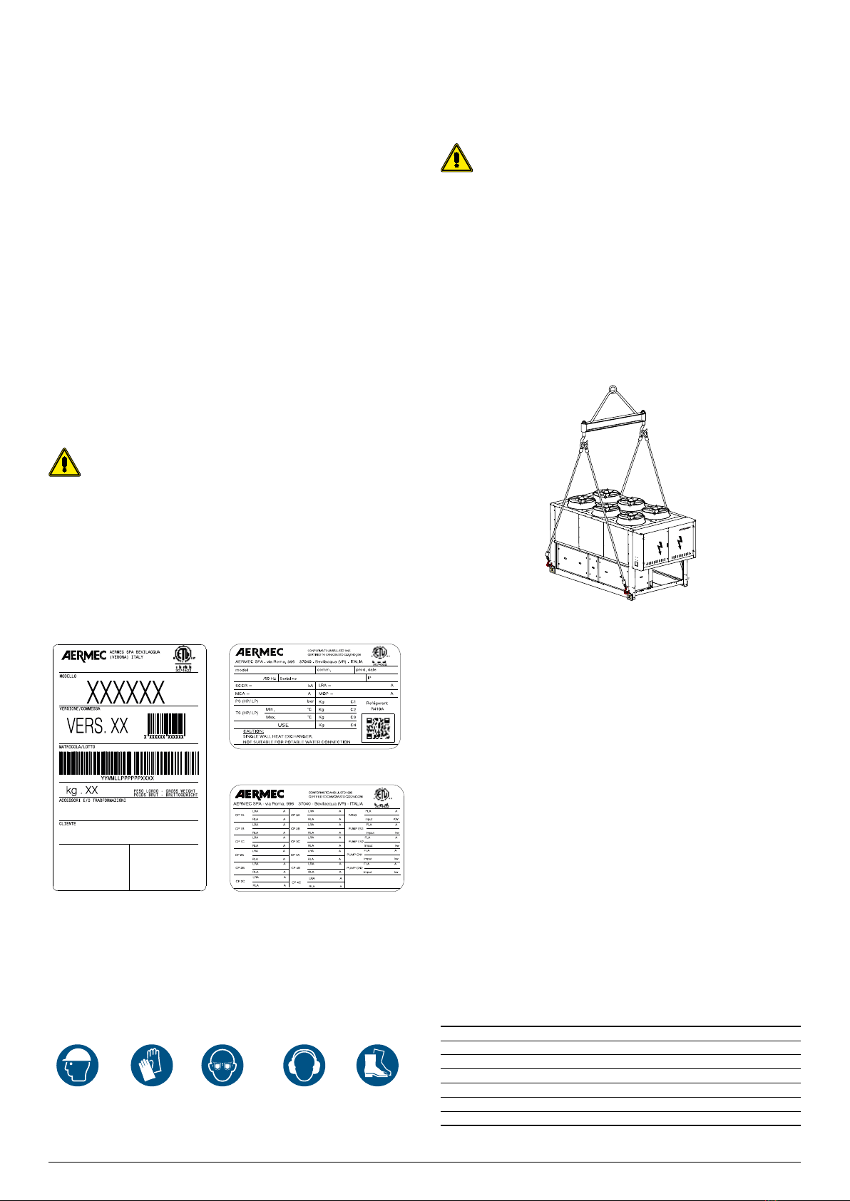
Personal protective
equipment (PPE)
(1)
Operations
Handling Installation and/or
maintenance Welding or brazing
Safety gloves,
helmet, goggles,
safety footwear,
protective garments.
•••
Earmus • •
(1) It is recommended to follow the instructions in EN 378-3.
— Observe the laws in force in the country of unit installation that concern use and
disposal of the packaging, the products used for cleaning and maintenance,
and for managing the end of the unit's service life;
— Repair and maintenance work must be performed by AermecTechnical Service.
Do not modify or tamper with the unit as dangerous situations may be created
and the equipment manufacturer will not be liable for any damage caused;
— In the case of abnormal operation, or if liquids leak, move the main switch for
the system to "o" and close the interception taps. Call the local AermecTechni-
cal Service and do not work on the equipment personally;
— The unit must be installed in structures that are protected against atmospheric
discharges, as required by applicable laws and technical standards;
— The equipment contain refrigerant gas: proceed carefully to prevent damaging
the gas circuit or the nned coil;
— Based on EU regulation 517/2014 concerning certain uorinated greenhouse
gases, it is mandatory to indicate the total quantity of refrigerant contained in
the installed system. This value is indicated on the rating plate on the unit;
— This unit contains uorinated greenhouse gases covered by the Kyoto Proto-
col. Maintenance and disposal operations must be only carried out by qualied
personnel;
— This manual is an integral part of the unit and as a result it must be stored care-
fully and must always accompany it, even if transferred to another owner or
user, or if transferred to another plant. If damaged or lost, a copy can be down-
loaded from our website www.aermec.com
— The overall re risk assessment at the place of installation (i.e. re load calcula-
tion) is the responsibility of the user.
— Perform the plant connections following the indications provided in this man-
ual.
IT IS FORBIDDEN TO:
— It is not permitted to walk on the machine or to place other items on it: no part
of the unit may be used as a walkway or support for goods or people. Periodical-
ly check and repair or, if necessary, replace any component or pipe that shows
signs of damage. Use a platform, or suitable scaolding to work at higher levels;
— Remove the protections from mobile elements while the unit is running;
— Touch the moving parts, stand between them or insert pointed objects through
the grids.
— Any technical intervention or cleaning operation before having disconnected
the appliance from the mains electric power supply: by positioning the system
master switch and the main device switch at "OFF".
— Modify the safety or regulation devices. The devices must be replaced by the
After-sales Technical Service Aermec, using only original components.
— Pull, detach or twist the electrical cables coming out of the unit even if it is dis-
connected from the mains electric power supply;
— To dispose of the packaging material in the environment or leave it within reach
of children: as it may be a potential source of danger. Therefore it must be dis-
posed of according to what is dened by current laws.
ESSENTIAL SAFETY RULES
Any technical intervention must be performed by qualied and author-
ised personnel. The personnel performing the work must have been
trained and be familiar with this type of product and its installation.
The machine must only be employed for the use for which it was made; any other
use can be dangerous and void the warranty;
It is not permitted to walk on the machine or to place other items on it. No part
of the unit may be used as a walkway or support for goods or people. Periodically

8 22.11 5806712_07
check and repair or, if necessary, replace any component or pipe that shows signs of
damage. Use a platform, or suitable scaolding to work at higher levels.
All the precautions concerning the handling of refrigerant must be observed in ac-
cordance with current regulations.
The overall re risk assessment at the place of installation (i.e. re load calculation)
is the responsibility of the user;
Keep re estinguishers near the machine suitable for putting out res on electrical
equipment and, for lubricant oil of the compressor and the refrigerant;
PRECAUTIONS CONCERNING THE HYDRAULIC CIRCUIT
Perform the plant connections following the indications provided in the manual:
— It is necessary to install a water lter and a ow switch on the heat ex-
changers, otherwise the warranty shall be void;
— During commissioning, it is mandatory to carry out a seal test on the air
of the hydraulic circuit (minimum pressure 2.5 bar and a search for leak-
ages on every joint - e.g. using leak detector foam or soap + water) before
lling it with glycol. This is to avoid the need for corrections due to leaks
caused, for example, during the transportation/handling stage (even
though the circuit is tested before leaving the Aermec factory);
— Do not bend or strike pipes containing pressurised uids. Do not exceed the
maximum permissible pressure (PS) of the unit's water circuit;
— Before removing elements along the pressurised water circuits, intercept the
concerned section of pipe and release the uid gradually until the pressure is
balanced with the atmospheric pressure;
— Even with the unit o, prevent the uid in contact with the heat exchangers
exceed the temperature limits indicated in the documentation and freeze;
— Do not send liquids to the heat exchangers other than water or its mixtures
with ethylene/propylene glycol in concentrations above what is indicated in the
technical documentation;
PRECAUTIONS CONCERNING THE ELECTRICAL CIRCUIT
— Perform the plant connections following the indications provided in this man-
ual;
— Do not use cables with inadequate section or ying connections, not even for
limited periods or emergencies;
— Check the unit is properly earthed before starting it;
— Before opening the electrical panel, disconnect the unit from the mains by
means of the external isolator;
— In case of units with shunt capacitors, wait 3 minutes from when power supply
was disconnected from the unit before accessing inside the electrical panel;
— If the unit has components such as integrated inverters, disconnect the power
supply and wait at least 15 minutes before accessing it for maintenance opera-
tions: the internal components remain energised for this period, generating the
risk of electrocution;
— The safety devices must be maintained ecient and periodically checked as
prescribed by current regulations;
PRECAUTIONS CONCERNING THE COOLING CIRCUIT
— The overall re risk assessment at the place of installation (i.e. re load calcula-
tion) is the responsibility of the user;
— Keep re estinguishers near the machine suitable for putting out res on elec-
trical equipment and, for lubricant oil of the compressor and the refrigerant;
— The unit contains pressurised refrigerant gas: no operation may be performed
on pressurised equipment except during maintenance, which must be per-
formed by skilled and qualied personnel;
— Perform brazing or welding only on empty pipes and clear of any lubricating
oil residues; do not near ames or other heat sources to the pipes containing
refrigerant uid;
— Do not work with naked ames near the unit;
— In order to avoid an environmental risk, make sure that any uid leaks are recov-
ered in suitable devices in compliance with local regulations;
— Do not use your hands to control any refrigerant leaks;
— An accidental release of refrigerant may cause risk of suocation due to a lack of
oxygen: install the machine in a well ventilated environment in accordance with
EN 378-3 and local regulations currently in force. Those who come into contact
with the machine must be equipped with a leak detector that is calibrated and
validated to reveal any used refrigerant leaks.
— The unit is tted out with overpressure relief devices (safety valves): in the event
that these devices start, the refrigerant gas is released at high temperature and
high velocity. Prevent the gas ow from harming people or things;
— Install the unit at a distance enough from the exhaust wells;
— Keep all lubricants in properly marked containers. Do not keep ammable liq-
uids near the plant;
PREVENTIONS
— Make sure that the protections of mobile elements are correctly in place before
restarting the unit;
— Fans, motors and belt drives may be in motion: always wait for them to stop and
take appropriate precautions to prevent their activation before accessing them;
— The machine and the pipes have very hot and very cold surfaces that lead to
risk of burns;
— Before opening a machine panel, ascertain whether it is or not rmly connected
to it by hinges;
— Louvers of the heat exchangers, edges of the components and metal panels
can generate cuts;
— The installation must ensure that the temperature of the uid entering the unit
is maintained stable and within the provided limits; therefore, pay attention to
the adjustment of any external thermal exchange and control devices (drycool-
er, evaporating towers, area valves, ...), to the adequate dimensioning of the
mass of uid circulating in the plant (in particular when plant areas are exclud-
ed) and to install systems for the recirculation of the necessary uid ow rate so
as to maintain the machine temperatures within the allowed limits (e.g. during
the start-up phase);
— The material used for the machine protective packaging must always be kept
out of the reach of children as it is a source of danger;
— In units with compressors in parallel, do not disable the individual compressors
for long periods;
— As this unit is intended only for installation outdoors and in an area with autho-
rised access only, there are no load limits.
WARNINGS
The unit has the following safety labels to indicate the potential risks (placed on
potentially hazardous parts or close to them).
Electricity
Warning:
Sharp element
Warning: Warning:
Moving parts
Warning:
Hot surface
Check periodically that the safety labels are in the correct position on the machine,
and replace them if necessary.

22.11 5806712_07 9
OPERATING RANGE
In their standard conguration, the units are not suitable for installation in salty environments.
The values indicated in the table refer to the min. and max. limits of the unit, valid for T = -22.0 °F (cooling mode) and ∆T = -22.9 °F (heating mode).
If the unit is installed in particularly windy locations the provision of wind barriers may be necessary to avoid malfunctions. It should be installed if wind speed is above 4.3 knot.
WARNING: Under no circumstances does the unit have to be operated outside the operating limit under penalty of the warranty expiration. Aermec S.p.A.
cannot be held responsible for any malfunction of the units which are operated outside the established limits and for their consequences.
OPERATING COOLING MODE RANGE
Key
A Outdoor air temperature (°F)
B Water produced (°F)
1 Standard mode
B
1
A
0
14 20
40
60
80
100
120
114.8
140
°F
30 40
39.2 44.6 64.450 60 70
104
°F
OPERATING HEATING MODE RANGE
Key
A Outdoor air temperature - dry
bulb (°F)
B Water produced (°F)
1 Standard mode
60
70
80
77
90
100
104
110
120
130
131
140
°F
-20 5
023 4020 60 80 107.6 120100
°F
B
1
A

10 22.11 5806712_07
3 PREINSTALLATION
RECEIVING THE PRODUCT
Inspection upon receipt
To prevent damage during transport, the units are completely wrapped in packag-
ing and protected by plastic elements.
The machine is also wrapped in packaging.We recommend keeping this protection
during all transport and lifting operations and not remove the plastic elements until
commissioning.
There is a document envelope located inside the access panel to the electrical parts
that contains the following material:
— Instruction manual for the installer and the technical service, with the declara-
tion of conformity on the rst pages
— Unit user manual
— Wiring diagrams
The instruction manual is an integral part of the unit and therefore it must be re-
covered, read and stored carefully. If lost, a copy can be found in the support area
online at www.aermec.com.
Upon receipt:
— Check that the exterior has not been damaged in any way;
— Check that the lifting and transport devices are appropriate to the type of
equipment and compliant with the transport and handling instructions at-
tached to this manual;
— Check that the accessories required for on-site installation have been delivered
and are operational;
— Check that the equipment supplied corresponds to the order and delivery note.
ATTENTION! If the product is damaged, send a registered letter with
the details of the problem to the shipping company within 48 work-
ing hours from delivery.
Product identication
Aermec products are identiable by the packaging label that shows the product
identication data, and by the rating plate that shows the performance and iden-
tication technical data of the unit in your possession.
When the unit is positioned, make sure that the rating plate is well visible as the
information provided on it is essential for correct maintenance.
Packaging label Technical plate
Compressor data plate
PACKAGING HANDLING AND REMOVAL
Before carrying out the packaging removal or transport operations, put on personal
protective equipment and use devices and instruments suitable for the dimensions
and weigh of the equipment.
All handling operations must be performed by qualied personnel in strict compli-
ance with all the applicable safety procedures.
The handling operations must be carried out carefully to prevent damage. The unit
may only be handled in a horizontal position and only from its base.
It is prohibited to dispose of the packaging material in the environ-
ment or leave it within reach of children: as it may be a potential source
of danger. Therefore it must be disposed of according to what is dened
by current laws.
The unit may be handled in two ways, using:
— A hoist or a crane;
— A forklift.
LIFTING WITH A HOIST OR CRANE
Before lifting the unit, place protections between the belts (or ropes and chains)
and the framework to prevent damage to the structure.
In case of handling with hoist or crane, the unit is supplied with eye-
bolts; they must be lifted using suitable straps hooked to all the in-
stalled eyebolts.
The following is required:
— Follow all safety regulations and standards;
— Before lifting, check the specic weight on the technical plate;
— Wear safety glasses, work gloves and safety shoes;
— Pay the utmost attention to heavy and bulky equipment during lifting and han-
dling, and when placing it on the ground;
— All panels must be tightly xed before moving the unit;
— Use all, and only, the lifting points indicated;
— Use ropes in compliance with Standards and of equal length;
— Use a spacer in accordance with the sling (not included) see drawing;
— Handle the unit with care and without sudden movements;
— Do not stand under the unit during lifting;
STORAGE
It is possible that the units may not be immediately installed upon receipt. If they
are stored for a medium-long period of time, the following procedures are recom-
mended:
— The units cannot be stacked;
— Check for any damage
— Make sure there is no water inside the hydraulic systems;
— Do not remove the protections from the heat exchanger;
— Do not remove the plastic protective lms;
— Make sure that the electrical panels are closed;
— Before using the equipment, put all the supplied items in a dry and clean loca-
tion so that they can be used in the future.
The minimum and maximum unit storage temperature depends on the
type of refrigerant used, see the table. Above this limit, there is a risk of
refrigerant leaks through the pressure relief valves.
Maximum storage temperature
Refrigerant Type Class Min temp. (°F) Max. temp. (°F)
R134a HFC A1 -4.0 °F < 122.0 °F
R410A HFC A1 -4.0 °F < 122.0 °F
R513A HFC A1 -4.0 °F < 122.0 °F
R32 HFC A2L -4.0 °F < 122.0 °F
R1234ze HFO A2L -4.0 °F < 122.0 °F

22.11 5806712_07 11
POSITIONING
The units must:
— They must be installed in an area that cannot be accessed by the public and/or
be protected against access by unauthorised persons, if necessary also install
fences;
— Be positioned on a levelled surface that is able to support the weight of the
unit with the refrigerant load and complete water, in addition to the occasional
presence of maintenance equipment;
— In locations exposed to frost, if the unit is installed on soil, the support base
must rest on concrete columns with a depth greater than the normal depth of
frost of the soil. It is always advisable to build a support base separate from the
main building to avoid the transmission of vibrations;
— If the machine is installed in a place potentially subject to snow accumulation
or ice formations in the base, it is recommended to install the unit with at least
300 mm above the ground;
— It is recommended to use suitably sized anti-vibration supports.
— The unit must be xed to the anti-vibration supports and these rmly xed
to the concrete base, see chapter weight distribution and minimum technical
spaces. Check that the contact surfaces of the anti-vibration supports are lev-
elled at the base. If necessary, use spacers or level the base, but in any case make
sure that the anti-vibration supports are placed at on the surfaces of the base;
— The use of anti-vibration supports MUST be done in combination with the in-
stallation of exible couplings in the unit's water pipes. The anti-vibration sup-
ports must be xed to the unit BEFORE being earthed. AERMEC is not responsi-
ble for selecting the capacity of the anti-vibration supports;
— Each side of the unit must have space to allow all routine and extraordinary
maintenance to be performed, the vertical air exhaust must not be obstructed.
PLACE OF INSTALLATION
All the units in this series are designed to be installed outdoors: on
roofs or on the ground in places where there are no obstacles that could
reduce the air ow towards the nned heat exchanger coils.
The location of the unit must be dened by the system designer or a person who is
an expert in the material and must consider both the purely technical requirements
as well as any local laws in force.
For unit installation it is important to perform the following preliminary prepara-
tion tasks:
The following must be avoided
— Positioning in air shafts, holes and/or basement windows;
— Obstacles or barriers that cause the return of the exhaust air;
— Locations with aggressive atmospheres;
— Areas in which the unit's noise level could be amplied due to reverberations
or resonance;
— Positioning in corners where there is usually an accumulation of dust, leaves
and anything else that could reduce the eciency of the equipment, obstruct-
ing the passage of air;
— That the air expulsion from the equipment can penetrate into living areas
through doors or windows;
— That the air expulsed by the unit is countered by adverse wind;
— For the positioning of the air-cooled units for outdoor use, choose a place that
is not exposed to excessive wind (install windbreaks if the wind speed exceeds
4.3 knot).
1 Side-by-side units; 2 Windbreak barrier recommended for wind
above4.3 knot;
3 Installation not permitted;
A. 91 in
321
A

12 22.11 5806712_07
4 MINIMUM TECHNICAL SPACES
For all units, it is fundamental to respect the minimum distances in order to guarantee optimal ventilation to the nned heat exchanger coils to avoid the following:
— The generation of hazardous atmospheres in the case of refrigerant gas leaks;
— Return of hot air;
— Insucient air ow to the nned heat exchanger coils.
Each side of the unit must have space to allow all routine and extraordinary maintenance to be performed.
The air suction inlet and the vertical air exhaust must not be obstructed.
The following images indicate the minimum required space:
SINGLE INSTALLATION
1 42 in
B1
B2
C1
C2
A1
B1
B2
C1
C2
A1
1
1
1
1
* Minimum technical space, to be ensured in order for the chiller to work properly and for possible maintenance.
The drawings are provided solely as examples.
VERSION A
Size 0800 0900 1000 1250 1400 1500 1650 1800
Minimum technical spaces
B1 A in 31.5 31.5 31.5 31.5 31.5 31.5 31.5 31.5
B2 A in 43.3 43.3 43.3 43.3 43.3 43.3 43.3 43.3
C1 A in 31.5 31.5 31.5 31.5 31.5 31.5 31.5 31.5
C2 A in 31.5 31.5 31.5 31.5 31.5 31.5 31.5 31.5
MULTIPLE INSTALLATION
The minimum distances indicated above guarantee unit operation in the majority of applications. There are however specic situations that involve the installation of multiple
units:
A 91 in B 59 in
A B

22.11 5806712_07 13
5 POSITION OF THE VIBRATION DAMPERS
For DIMENSIONS and POSITION OF HYDRAULIC CONNECTIONS refer to the DWG le on site www.aermec.com or selection program Magellano
View from below
NRP- 0800 - 1000
71,9in 71,9in
Ø20
3,9in
2,0in
3,9in
NRP- 1250-1800
Ø20
2,0in
15,7in 15,7in75,4in 75,4in28,3in

14 22.11 5806712_07
6 WEIGHT DISTRIBUTION AND CENTRES OF GRAVITY
Top view
11
33
557
668
44
22
Xg
Yg
Y
X
Xg
Yg
Y
X
EMPTY
Version
Integrated
hydronic kit user
side
Integrated
hydronic kit,
recovery side
0800 0900 1000 1250 1400 1500 1650 1800
Empty weight
A 00 00 lbs 7,143 7,496 7,474 9,943 10,031 10,119 10,538 10,847
A 00 R1/R3 lbs 7,452 7,804 7,804 10,318 10,406 10,494 10,913 11,222
A 00 R2/R4 lbs 7,738 8,091 8,069 10,626 10,737 10,825 11,222 11,530
A P1/P3 00 lbs 7,496 7,848 7,826 10,362 10,450 10,538 10,957 11,244
A P1/P3 R1/R3 lbs 7,804 8,157 8,157 10,737 10,825 10,913 11,332 11,618
A P1/P3 R2/R4 lbs 8,091 8,444 8,422 11,045 11,133 11,222 11,640 11,949
A P2/P4 00 lbs 7,650 8,003 7,981 10,582 10,670 10,759 11,177 11,464
A P2/P4 R1/R3 lbs 7,959 8,311 8,289 10,957 11,045 11,133 11,552 11,839
A P2/P4 R2/R4 lbs 8,245 8,598 8,576 11,266 11,354 11,442 11,861 12,170
X
A 00 00 in 68.3 70.7 69.4 93.1 93.3 93.0 98.9 97.5
A 00 R1/R3 in 69.4 71.7 70.6 94.3 94.5 94.2 99.9 98.4
A 00 R2/R4 in 70.4 72.6 71.3 95.3 95.5 95.2 100.6 99.2
A P1/P3 00 in 67.4 69.6 68.5 92.3 92.5 92.2 97.9 96.5
A P1/P3 R1/R3 in 68.5 70.6 69.5 93.4 93.7 93.4 98.8 97.5
A P1/P3 R2/R4 in 69.3 71.5 70.4 94.4 94.6 94.3 99.6 98.3
A P2/P4 00 in 67.0 69.3 68.0 91.8 92.1 91.7 97.4 96.0
A P2/P4 R1/R3 in 68.0 70.2 69.1 93.0 93.2 92.9 98.3 97.0
A P2/P4 R2/R4 in 68.9 71.1 70.0 93.9 94.1 93.9 99.1 97.8
Y
A 00 00 in 7,137.6 7,490.3 7,468.3 9,935.4 10,023.4 10,111.3 10,530.0 10,838.8
A 00 R1/R3 in 7,446.3 7,798.1 7,798.1 10,310.2 10,398.1 10,486.0 10,904.7 11,213.5
A 00 R2/R4 in 7,732.1 8,084.8 8,062.9 10,617.9 10,728.9 10,816.8 11,213.5 11,521.3
A P1/P3 00 in 7,490.3 7,842.0 7,820.0 10,354.1 10,442.0 10,530.0 10,948.7 11,235.5
A P1/P3 R1/R3 in 7,798.1 8,150.8 8,150.8 10,728.9 10,816.8 10,904.7 11,323.4 11,609.2
A P1/P3 R2/R4 in 8,084.8 8,437.6 8,415.6 11,036.6 11,124.5 11,213.5 11,631.1 11,939.9
A P2/P4 00 in 7,644.2 7,996.9 7,974.9 10,574.0 10,661.9 10,750.8 11,168.5 11,455.3
A P2/P4 R1/R3 in 7,953.0 8,304.7 8,282.7 10,948.7 11,036.6 11,124.5 11,543.2 11,830.0
A P2/P4 R2/R4 in 8,238.7 8,591.5 8,569.5 11,257.4 11,345.4 11,433.3 11,852.0 12,160.7
1
A 00 00 % 10.1% 9.1% 9.5% 10.1% 10.0% 10.0% 8.9% 9.2%
A 00 R1/R3 % 9.5% 8.6% 9.0% 9.8% 9.7% 9.7% 8.6% 8.9%
A 00 R2/R4 % 9.0% 8.1% 8.6% 9.6% 9.4% 9.5% 8.4% 8.6%
A P1/P3 00 % 10.8% 9.7% 10.2% 10.2% 10.0% 10.1% 9.0% 9.2%
A P1/P3 R1/R3 % 10.2% 9.2% 9.6% 9.9% 9.7% 9.8% 8.7% 8.9%
A P1/P3 R2/R4 % 9.6% 8.7% 9.2% 9.6% 9.5% 9.6% 8.4% 8.7%
A P2/P4 00 % 11.1% 10.0% 10.4% 10.2% 10.1% 10.1% 9.0% 9.3%
A P2/P4 R1/R3 % 10.4% 9.4% 9.9% 9.9% 9.8% 9.8% 8.7% 9.0%
A P2/P4 R2/R4 % 9.9% 9.0% 9.4% 9.7% 9.5% 9.6% 8.5% 8.8%

22.11 5806712_07 15
Version
Integrated
hydronic kit user
side
Integrated
hydronic kit,
recovery side
0800 0900 1000 1250 1400 1500 1650 1800
2
A 00 00 % 12.1% 11.3% 12.8% 12.9% 12.8% 12.9% 9.2% 9.9%
A 00 R1/R3 % 11.0% 10.4% 11.7% 12.1% 12.0% 12.2% 8.7% 9.4%
A 00 R2/R4 % 10.1% 9.6% 10.8% 11.6% 11.5% 11.6% 8.4% 9.0%
A P1/P3 00 % 11.9% 11.3% 12.6% 12.3% 12.2% 12.3% 8.9% 9.6%
A P1/P3 R1/R3 % 10.9% 10.4% 11.6% 11.6% 11.5% 11.7% 8.5% 9.1%
A P1/P3 R2/R4 % 10.1% 9.6% 10.8% 11.1% 11.0% 11.2% 8.1% 8.8%
A P2/P4 00 % 11.8% 11.2% 12.5% 12.0% 11.9% 12.0% 8.7% 9.4%
A P2/P4 R1/R3 % 10.9% 10.3% 11.5% 11.4% 11.3% 11.4% 8.3% 9.0%
A P2/P4 R2/R4 % 10.1% 9.6% 10.7% 10.9% 10.8% 10.9% 8.0% 8.6%
3
A 00 00 % 31.7% 30.4% 28.6% 17.7% 17.5% 17.6% 18.1% 18.7%
A 00 R1/R3 % 32.8% 31.4% 29.7% 16.7% 16.5% 16.7% 17.0% 17.7%
A 00 R2/R4 % 33.6% 32.3% 30.6% 15.9% 15.7% 15.9% 16.2% 16.9%
A P1/P3 00 % 33.3% 32.0% 30.2% 20.3% 20.0% 20.1% 20.6% 21.1%
A P1/P3 R1/R3 % 34.3% 32.9% 31.2% 19.2% 18.9% 19.1% 19.5% 20.0%
A P1/P3 R2/R4 % 35.1% 33.7% 32.1% 18.4% 18.1% 18.3% 18.6% 19.2%
A P2/P4 00 % 34.0% 32.6% 30.9% 21.6% 21.3% 21.4% 21.9% 22.3%
A P2/P4 R1/R3 % 34.9% 33.5% 31.9% 20.5% 20.2% 20.3% 20.8% 21.2%
A P2/P4 R2/R4 % 35.6% 34.3% 32.7% 19.6% 19.4% 19.5% 19.9% 20.4%
4
A 00 00 % 37.7% 38.0% 38.4% 22.5% 22.4% 22.7% 18.7% 20.3%
A 00 R1/R3 % 37.8% 38.1% 38.5% 20.7% 20.5% 20.9% 17.3% 18.8%
A 00 R2/R4 % 37.9% 38.1% 38.6% 19.2% 19.1% 19.5% 16.2% 17.6%
A P1/P3 00 % 36.7% 37.0% 37.5% 24.4% 24.2% 24.6% 20.5% 21.9%
A P1/P3 R1/R3 % 36.8% 37.1% 37.6% 22.5% 22.4% 22.7% 19.0% 20.4%
A P1/P3 R2/R4 % 36.9% 37.2% 37.7% 21.1% 21.0% 21.3% 17.9% 19.2%
A P2/P4 00 % 36.3% 36.7% 37.1% 25.3% 25.1% 25.4% 21.3% 22.7%
A P2/P4 R1/R3 % 36.4% 36.8% 37.2% 23.4% 23.3% 23.6% 19.8% 21.2%
A P2/P4 R2/R4 % 36.5% 36.8% 37.3% 22.0% 21.9% 22.2% 18.7% 20.0%
5
A 00 00 % 3.8% 5.0% 4.6% 13.4% 13.7% 13.3% 17.8% 16.1%
A 00 R1/R3 % 4.2% 5.2% 4.9% 15.4% 15.7% 15.3% 19.7% 17.9%
A 00 R2/R4 % 4.4% 5.5% 5.1% 17.0% 17.2% 16.9% 21.3% 19.4%
A P1/P3 00 % 3.5% 4.6% 4.3% 12.1% 12.4% 12.1% 16.4% 14.7%
A P1/P3 R1/R3 % 3.8% 4.9% 4.5% 14.2% 14.4% 14.1% 18.3% 16.6%
A P1/P3 R2/R4 % 4.1% 5.1% 4.8% 15.8% 16.0% 15.7% 19.8% 18.1%
A P2/P4 00 % 3.3% 4.5% 4.1% 11.5% 11.8% 11.5% 15.6% 14.1%
A P2/P4 R1/R3 % 3.6% 4.7% 4.4% 13.5% 13.8% 13.5% 17.5% 15.9%
A P2/P4 R2/R4 % 3.9% 5.0% 4.6% 15.1% 15.3% 15.0% 19.1% 17.4%
6
A 00 00 % 4.5% 6.2% 6.2% 17.0% 17.5% 17.2% 18.5% 17.4%
A 00 R1/R3 % 4.8% 6.3% 6.3% 19.1% 19.5% 19.2% 20.1% 19.0%
A 00 R2/R4 % 5.0% 6.4% 6.4% 20.6% 21.0% 20.7% 21.3% 20.3%
A P1/P3 00 % 3.8% 5.4% 5.3% 14.6% 15.1% 14.8% 16.2% 15.3%
A P1/P3 R1/R3 % 4.1% 5.5% 5.5% 16.6% 17.1% 16.8% 17.8% 16.9%
A P1/P3 R2/R4 % 4.3% 5.6% 5.6% 18.2% 18.5% 18.3% 19.1% 18.2%
A P2/P4 00 % 3.5% 5.0% 5.0% 13.5% 13.9% 13.7% 15.2% 14.3%
A P2/P4 R1/R3 % 3.8% 5.2% 5.1% 15.5% 15.9% 15.6% 16.7% 15.9%
A P2/P4 R2/R4 % 4.0% 5.3% 5.3% 17.0% 17.4% 17.1% 18.0% 17.1%
7
A 00 00 % - - - 2.8% 2.7% 2.7% 4.3% 4.1%
A 00 R1/R3 % - - - 2.8% 2.7% 2.7% 4.2% 4.0%
A 00 R2/R4 % - - - 2.7% 2.7% 2.7% 4.2% 4.0%
A P1 00/R1/R3 % - - - 2.7% 2.7% 2.7% 4.2% 4.0%
A P2 00 % - - - 2.7% 2.7% 2.7% 4.2% 4.0%
A P3 00/R1/R3 % - - - 2.7% 2.7% 2.7% 4.2% 4.0%
A P4 00 % - - - 2.7% 2.7% 2.7% 4.2% 4.0%
A P1 R2/R4 % - - - 2.7% 2.7% 2.7% 4.1% 3.9%
A P2 R1/R3 % - - - 2.7% 2.7% 2.7% 4.1% 3.9%
A P3 R2/R4 % - - - 2.7% 2.7% 2.7% 4.1% 3.9%
A P4 R1/R3 % - - - 2.7% 2.7% 2.7% 4.1% 3.9%
A P2/P4 R2/R4 % - - - 2.7% 2.7% 2.6% 4.1% 3.9%
8
A 00 00 % - - - 3.5% 3.5% 3.5% 4.5% 4.4%
A 00 R1/R3 % - - - 3.4% 3.4% 3.4% 4.3% 4.3%
A 00 R2/R4 % - - - 3.3% 3.3% 3.3% 4.2% 4.2%
A P1/P3 00 % - - - 3.3% 3.3% 3.3% 4.2% 4.2%
A P1 R1/R3 % - - - 3.2% 3.2% 3.2% 4.1% 4.0%
A P2 00 % - - - 3.2% 3.2% 3.2% 4.1% 4.0%
A P3 R1/R3 % - - - 3.2% 3.2% 3.2% 4.1% 4.0%
A P4 00 % - - - 3.2% 3.2% 3.2% 4.1% 4.0%
A P1 R2/R4 % - - - 3.1% 3.1% 3.1% 3.9% 3.9%
A P2 R1/R3 % - - - 3.1% 3.1% 3.1% 3.9% 3.9%
A P3 R2/R4 % - - - 3.1% 3.1% 3.1% 3.9% 3.9%
A P4 R1/R3 % - - - 3.1% 3.1% 3.1% 3.9% 3.9%
A P2/P4 R2/R4 % - - - 3.0% 3.0% 3.0% 3.8% 3.8%
- not available

16 22.11 5806712_07
DURING OPERATION
Version
Integrated
hydronic kit user
side
Integrated
hydronic kit,
recovery side
0800 0900 1000 1250 1400 1500 1650 1800
Weight
functioning
A 00 00 lbs 7,209 7,584 7,584 10,097 10,185 10,296 10,737 11,045
A 00 R1/R3 lbs 7,562 7,915 7,915 10,494 10,582 10,692 11,133 11,442
A 00 R2/R4 lbs 7,848 8,201 8,201 10,803 10,913 11,001 11,442 11,751
A P1/P3 00 lbs 7,584 7,959 7,959 10,516 10,626 10,737 11,177 11,486
A P1/P3 R1/R3 lbs 7,937 8,289 8,289 10,913 11,023 11,111 11,552 11,861
A P1/P3 R2/R4 lbs 8,223 8,576 8,576 11,244 11,332 11,442 11,883 12,192
A P2/P4 00 lbs 7,738 8,113 8,113 10,759 10,847 10,957 11,398 11,707
A P2/P4 R1/R3 lbs 8,091 8,444 8,444 11,133 11,244 11,354 11,773 12,103
A P2/P4 R2/R4 lbs 8,356 8,730 8,730 11,464 11,552 11,662 12,103 12,412
X
A 00 00 in 68.7 70.9 69.8 93.6 93.8 93.5 99.4 98.0
A 00 R1/R3 in 69.8 72.0 70.8 94.8 95.1 94.7 100.3 99.0
A 00 R2/R4 in 70.7 72.8 71.7 95.8 96.0 95.6 101.1 99.7
A P1/P3 00 in 67.6 69.8 68.7 92.7 92.9 92.6 98.3 97.0
A P1/P3 R1/R3 in 68.7 70.9 69.8 93.9 94.1 93.8 99.3 98.0
A P1/P3 R2/R4 in 69.6 71.7 70.6 94.9 95.1 94.7 100.0 98.7
A P2/P4 00 in 67.2 69.4 68.3 92.3 92.5 92.2 97.8 96.5
A P2/P4 R1/R3 in 68.3 70.4 69.3 93.5 93.7 93.4 98.8 97.5
A P2/P4 R2/R4 in 69.3 71.3 70.2 94.4 94.6 94.3 99.5 98.2
Y
A 00 00 in 46.9 47.9 49.4 48.3 48.5 48.6 43.9 44.8
A 00 R1/R3 in 46.2 47.2 48.6 47.7 47.8 48.0 43.5 44.4
A 00 R2/R4 in 45.7 46.7 48.1 47.2 47.4 47.5 43.1 44.0
A P1/P3 00 in 45.2 46.2 47.6 47.0 47.3 47.4 42.9 43.9
A P1/P3 R1/R3 in 44.6 45.6 47.0 46.6 46.7 46.8 42.6 43.5
A P1/P3 R2/R4 in 44.2 45.2 46.5 46.1 46.3 46.5 42.3 43.1
A P2/P4 00 in 44.4 45.6 47.0 46.5 46.7 46.8 42.5 43.4
A P2/P4 R1/R3 in 44.0 45.0 46.3 46.0 46.2 46.3 42.1 43.0
A P2/P4 R2/R4 in 43.6 44.6 45.9 45.6 45.7 45.9 41.8 42.7
1
A 00 00 % 10.0% 9.0% 9.4% 10.0% 9.8% 9.9% 8.7% 9.0%
A 00 R1/R3 % 9.4% 8.4% 8.8% 9.7% 9.5% 9.6% 8.4% 8.7%
A 00 R2/R4 % 8.9% 8.0% 8.4% 9.4% 9.3% 9.3% 8.2% 8.5%
A P1/P3 00 % 10.7% 9.7% 10.1% 10.1% 9.9% 9.9% 8.8% 9.1%
A P1/P3 R1/R3 % 10.0% 9.1% 9.5% 9.8% 9.6% 9.6% 8.5% 8.8%
A P1/P3 R2/R4 % 9.5% 8.6% 9.0% 9.5% 9.4% 9.4% 8.3% 8.6%
A P2/P4 00 % 11.0% 9.9% 10.3% 10.1% 9.9% 10.0% 8.8% 9.1%
A P2/P4 R1/R3 % 10.3% 9.3% 9.7% 9.8% 9.6% 9.7% 8.6% 8.8%
A P2/P4 R2/R4 % 9.8% 8.9% 9.3% 9.5% 9.4% 9.4% 8.3% 8.6%
2
A 00 00 % 11.8% 11.1% 12.4% 12.6% 12.5% 12.6% 9.0% 9.6%
A 00 R1/R3 % 10.7% 10.1% 11.3% 11.8% 11.7% 11.8% 8.5% 9.1%
A 00 R2/R4 % 9.9% 9.3% 10.5% 11.3% 11.2% 11.3% 8.1% 8.8%
A P1/P3 00 % 11.7% 11.0% 12.3% 12.0% 11.9% 12.0% 8.6% 9.3%
A P1/P3 R1/R3 % 10.6% 10.1% 11.2% 11.3% 11.2% 11.3% 8.2% 8.8%
A P1/P3 R2/R4 % 9.9% 9.4% 10.5% 10.8% 10.7% 10.9% 7.9% 8.5%
A P2/P4 00 % 11.6% 11.0% 12.2% 11.7% 11.6% 11.7% 8.5% 9.1%
A P2/P4 R1/R3 % 10.6% 10.1% 11.2% 11.1% 11.0% 11.1% 8.1% 8.7%
A P2/P4 R2/R4 % 9.9% 9.4% 10.4% 10.6% 10.5% 10.6% 7.8% 8.4%
3
A 00 00 % 31.9% 30.7% 29.0% 17.5% 17.3% 17.4% 17.8% 18.4%
A 00 R1/R3 % 33.0% 31.7% 30.1% 16.5% 16.3% 16.4% 16.7% 17.4%
A 00 R2/R4 % 33.9% 32.6% 31.0% 15.7% 15.5% 15.7% 15.9% 16.6%
A P1/P3 00 % 33.6% 32.3% 30.7% 20.1% 19.9% 20.0% 20.4% 20.9%
A P1/P3 R1/R3 % 34.6% 33.3% 31.7% 19.0% 18.8% 18.9% 19.3% 19.8%
A P1/P3 R2/R4 % 35.4% 34.0% 32.5% 18.2% 18.0% 18.1% 18.4% 19.0%
A P2/P4 00 % 34.3% 32.9% 31.3% 21.4% 21.2% 21.3% 21.7% 22.1%
A P2/P4 R1/R3 % 35.2% 33.9% 32.3% 20.3% 20.0% 20.2% 20.5% 21.0%
A P2/P4 R2/R4 % 35.9% 34.6% 33.1% 19.4% 19.2% 19.3% 19.6% 20.1%
4
A 00 00 % 37.6% 37.9% 38.3% 22.0% 21.9% 22.2% 18.3% 19.8%
A 00 R1/R3 % 37.7% 38.0% 38.5% 20.1% 20.0% 20.4% 16.8% 18.3%
A 00 R2/R4 % 37.8% 38.1% 38.5% 18.8% 18.7% 19.0% 15.8% 17.2%
A P1/P3 00 % 36.6% 36.9% 37.4% 24.0% 23.8% 24.2% 20.1% 21.5%
A P1/P3 R1/R3 % 36.7% 37.0% 37.5% 22.1% 22.0% 22.3% 18.6% 19.9%
A P1/P3 R2/R4 % 36.7% 37.1% 37.6% 20.7% 20.6% 20.9% 17.5% 18.8%
A P2/P4 00 % 36.2% 36.5% 37.0% 24.9% 24.7% 25.0% 20.9% 22.2%
A P2/P4 R1/R3 % 36.3% 36.6% 37.1% 23.0% 22.8% 23.1% 19.4% 20.7%
A P2/P4 R2/R4 % 36.3% 36.7% 37.2% 21.6% 21.5% 21.8% 18.3% 19.6%
5
A 00 00 % 3.9% 5.1% 4.7% 13.9% 14.2% 13.9% 18.5% 16.7%
A 00 R1/R3 % 4.3% 5.3% 5.0% 16.0% 16.3% 15.9% 20.4% 18.6%
A 00 R2/R4 % 4.5% 5.6% 5.2% 17.6% 17.8% 17.5% 21.9% 20.1%
A P1/P3 00 % 3.6% 4.7% 4.3% 12.6% 12.9% 12.6% 16.9% 15.3%
A P1/P3 R1/R3 % 3.9% 5.0% 4.6% 14.7% 15.0% 14.7% 18.9% 17.2%
A P1/P3 R2/R4 % 4.2% 5.2% 4.8% 16.3% 16.5% 16.2% 20.4% 18.7%
A P2/P4 00 % 3.4% 4.6% 4.2% 12.0% 12.3% 12.0% 16.2% 14.7%
A P2/P4 R1/R3 % 3.8% 4.8% 4.5% 14.1% 14.3% 14.0% 18.2% 16.6%
A P2/P4 R2/R4 % 4.0% 5.1% 4.7% 15.6% 15.9% 15.5% 19.6% 18.0%

22.11 5806712_07 17
Version
Integrated
hydronic kit user
side
Integrated
hydronic kit,
recovery side
0800 0900 1000 1250 1400 1500 1650 1800
6
A 00 00 % 4.6% 6.3% 6.2% 17.5% 18.0% 17.7% 18.9% 17.9%
A 00 R1/R3 % 4.9% 6.4% 6.3% 19.6% 20.0% 19.7% 20.6% 19.6%
A 00 R2/R4 % 5.1% 6.5% 6.4% 21.1% 21.5% 21.2% 21.7% 20.8%
A P1/P3 00 % 3.9% 5.4% 5.3% 15.0% 15.5% 15.2% 16.6% 15.7%
A P1/P3 R1/R3 % 4.1% 5.5% 5.5% 17.1% 17.5% 17.2% 18.2% 17.4%
A P1/P3 R2/R4 % 4.3% 5.7% 5.6% 18.5% 18.9% 18.7% 19.4% 18.6%
A P2/P4 00 % 3.6% 5.1% 5.0% 13.9% 14.3% 14.1% 15.6% 14.7%
A P2/P4 R1/R3 % 3.9% 5.2% 5.2% 15.9% 16.3% 16.1% 17.2% 16.3%
A P2/P4 R2/R4 % 4.1% 5.4% 5.3% 17.4% 17.7% 17.5% 18.3% 17.5%
7
A 00 00 % - - - 2.8% 2.8% 2.7% 4.4% 4.1%
A 00 R1/R3 % - - - 2.8% 2.8% 2.7% 4.3% 4.1%
A P1/P3 00 % - - - 2.8% 2.8% 2.7% 4.3% 4.1%
A 00 R2/R4 % - - - 2.8% 2.8% 2.7% 4.2% 4.0%
A P1 R1/R3 % - - - 2.8% 2.7% 2.7% 4.2% 4.0%
A P2 00/R1/R3 % - - - 2.8% 2.7% 2.7% 4.2% 4.0%
A P3 R1/R3 % - - - 2.8% 2.7% 2.7% 4.2% 4.0%
A P4 00/R1/R3 % - - - 2.8% 2.7% 2.7% 4.2% 4.0%
A P1/P3 R2/R4 % - - - 2.8% 2.7% 2.7% 4.1% 4.0%
A P2/P4 R2/R4 % - - - 2.8% 2.7% 2.7% 4.1% 3.9%
8
A 00 00 % - - - 3.6% 3.5% 3.5% 4.5% 4.4%
A 00 R1/R3 % - - - 3.4% 3.4% 3.4% 4.3% 4.3%
A 00 R2/R4 % - - - 3.3% 3.3% 3.3% 4.2% 4.2%
A P1/P3 00 % - - - 3.3% 3.3% 3.3% 4.2% 4.2%
A P1/P3 R1/R3 % - - - 3.2% 3.2% 3.2% 4.0% 4.0%
A P1/P3 R2/R4 % - - - 3.2% 3.1% 3.1% 3.9% 3.9%
A P2/P4 00 % - - - 3.2% 3.2% 3.2% 4.1% 4.0%
A P2/P4 R1/R3 % - - - 3.1% 3.1% 3.1% 3.9% 3.9%
A P2/P4 R2/R4 % - - - 3.1% 3.0% 3.0% 3.8% 3.8%
- not available

18 22.11 5806712_07
7 DIMENSIONAL TABLES
NRP 08001000
86,6in
96,5in
167,3in
NRP 0800-0900 60Hz
NRP 1000 60Hz
3.9 in
3.9 in 3.9 in
3.9 in

22.11 5806712_07 19
NRP 12501800
96,5in
226,4in
86,6in
21.7 in 43.3 in 80.8 in 43.3 in 21.7 in

20 22.11 5806712_07
8 HYDRAULIC CONNECTIONS
In particular, the unit is intended to be connected:
— to a hydronic system that must be designed to be classied according to EN
378-1 as an indirect ventilated system (ref EN 378-1; 2016, par. 5.5.2.2 ), as an
indirect vented closed system (ref EN 378-1;2016, par. 5.5.2.3 ), or as a double
indirect system according to EN 378-1 (ref. EN 378-1; 2016, par. 5.5.2.4 ).
— The intermediate uid (water or water-glycol mixture) is in direct communica-
tion with the occupied space and a refrigerant leak in the intermediate circuit
must be dissipated to the atmosphere outside the occupied space and in an
area that is suitably ventilated to prevent the generation of explosive atmos-
pheres.
— In particular, for a closed system this condition requires installing a properly
sized mechanical device in a suitable position of the hydronic circuit for the col-
lection and draining of the refrigerant. If drain and/or safety valves are installed
in the unit, they do not in any way replace this device.
— The automatic air drain must be installed in all the highest points of the hydrau-
lic circuit, outside the building and far from sources of ignition. In order to gua-
rantee that ammable refrigerant will not ow into the environment in the case
of leaks, it is recommended to install it with a primary and secondary circuit.
The units may be available with or without integrated hydronic kit, in any case:
WARNING! Clean the system carefully before connecting the unit:
this is done in order to eliminate possible residues such as welding spatter,
waste, rust or any other impurity from the pipes. These substances could
deposit inside and cause the equipment to malfunction. The connection
pipes must be properly supported so as not to burden the unit with their
weight.
WARNING! The choice and installation of components external to the
unit is up to the installer, who must operate according to the rules of
good technical design and in compliance with the regulations in force
in the country of destination.
WARNING! The hydraulic connection pipes to the unit must be suit-
ably dimensioned for the eective water ow rate requested by the
system when running. The water ow rate to the heat exchanger
must always be constant.
WARNING! The charge or discharge of the heat exchange uids must
be made during installation by qualied technicians using the t-
tings provided on the hydraulic circuit. Never use the unit heat ex-
changers to top-up the heat exchanger uid.
During commissioning, it is mandatory to carry out a seal test on
the air of the hydraulic circuit (minimum pressure 36.3 psi and a
search for leakages on every joint - e.g. using leak detector foam or
soap+water) before lling it with glycol. This is to avoid the need for
corrections due to leaks caused, for example, during the transporta-
tion/handling stage (even though the circuit is tested before leaving
the Aermec factory).
WARNING! Water lter and ow switch: It is necessary to install a water
lter and a ow switch upstream of each heat exchanger if they are not
supplied with the unit.
CONNECTIONS
Before starting the system, check that the hydraulic circuits are connected to the
correct heat exchangers. The water circulating pump must preferably be installed
upstream so that the evaporator/condenser is subjected to positive pressure. The
water inlet and outlet connections are indicated in the dimensions table in this
manual, or are available online at www.aermec.com
It is important to follow the recommendations (not complete) below:
— The water pipes must not transmit radial or axial forces or vibrations to the ex-
changers (use exible hoses to reduce the transmitted vibrations);
— It is necessary to install manual or automatic vent valves in the highest points
of the circuit and also provide discharge ttings in the lowest points to allow
emptying the entire circuit;
— To maintain the pressure in the circuits, you must install an expansion tank and
a safety valve;
— Respect the water inlet and outlet connections shown on the unit;
— Install manometer on the water inlet and outlet ttings;
— Install stop valve near the water inlet and outlet ttings;
— Install exible joints for the connection of the pipes;
— After performing a leak test, insulate the pipes to reduce heat loss and prevent
the formation of condensation;
— If the external water pipes are in an area where it is likely that the environment
temperature drops below 32.0 °F, insulate the pipes and provide an electric
heater. As an option, you can also protect the pipes inside the unit;
— Check the continuity of the earthing;
It is prohibited to operate the unit without an installed and clean wa-
ter lter.
The charge or discharge of the heat exchange uids must be made
during installation by qualied technicians using the ttings provid-
ed on the hydraulic circuit.
Never use the unit heat exchangers to top-up the heat exchanger
uid.
WATER CHARACTERISTICS
It is recommended before loading the system to analyse the water, the hydraulic
circuit must have all the devices necessary for treating the water.
The use of untreated water or water that is not treated properly can cause deposits
of incrustations, algae, mud or cause erosion or corrosion, causing serious damage
to the heat exchanger.
It is recommended to request the support of a specialised technician for the water
treatment in order to determine the quality of your water and any corrective inter-
ventions.
Aermec shall not be liable for any damage deriving from the use of "hard" water
that is not treated or that was improperly treated.
The following table provides an incomplete list of the water quality recommended
for the plate heat exchangers:
System: Chiller with plate heat exchanger
PH 7,5 - 9
Total hardness 4,5 - 8,5 °dH
Temperature < 65 °C
Oxygen content < 0,1 ppm
Max. glycol amount 50 %
Phosphates (PO) < 2ppm
Manganese (Mn) < 0,05 ppm
Iron (Fe) < 0,3 ppm
Alkalinity (HCO) 70 - 300 ppm
Chloride ions (Cl-) < 50 ppm
Sulphate ions (SO) < 50 ppm
Sulphide ion (S) None
Ammonium ions (NH) None
Silica (SiO) < 30 ppm
It is of fundamental importance to keep the oxygen concentration in
the water under control, especially in open vessel systems. This type
of system, in fact, is very sensitive to the phenomenon of extra-oxy-
genation of the water (an event that can be encouraged by the incor-
rect positioning of some components). This phenomenon can trigger
corrosion processes and subsequent drilling of the heat exchanger
and pipes.
NOTICE under no circumstances does the unit have to be operated
with water circulating on the heat exchanger whose characteristics
are dierent from those indicated in the table WATER CHARACTER-
ISTICS, under penalty of the warranty expiration. Aermec cannot be
held responsible for any malfunction of the units which are operated
with water whose characteristics are outside the limits in the table
WATER CHARACTERISTICS and for their consequences.
DISCHARGING SYSTEM
In the event the system is stopped during winter, the water in the heat exchanger
can freeze damaging the heat exchanger irreversibly.
To prevent danger of freezing, three solutions are possible:
1. Full water discharge from the unit;
Other manuals for NRP 0800
2
This manual suits for next models
7
Table of contents
Other AERMEC Industrial Equipment manuals
Popular Industrial Equipment manuals by other brands

Danuser
Danuser POSTMASTER/SLAB BLASTER Operator's manual

IOLINK
IOLINK BALLUFF BIS U-4A7-082-01C-07-S4 Configuration

Haufftechnik
Haufftechnik HSI 150-DT Assembly instruction

Haufftechnik
Haufftechnik HSD manual

Amanngirrbach
Amanngirrbach ARTEX Transfer Jig user manual

Oriental motor
Oriental motor FD12 operating manual