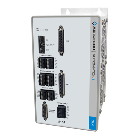
Aerotech Automation1 XL4s User manual
Other Aerotech Controllers manuals
Aerotech
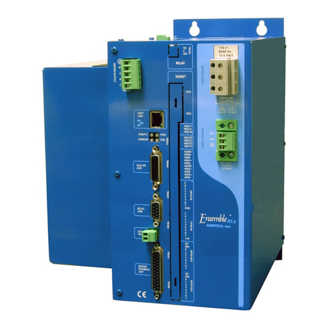
Aerotech A3200 Series User manual

Aerotech
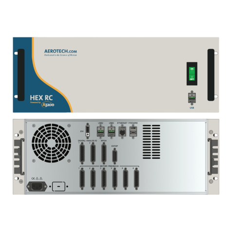
Aerotech APR200DR Series User manual

Aerotech
Aerotech A3200 Series User manual
Aerotech
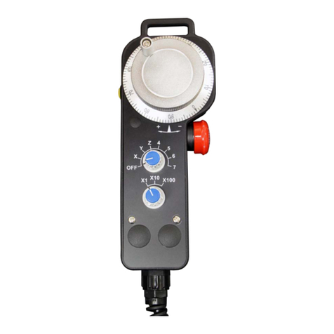
Aerotech MPG User manual

Aerotech
Aerotech APR100DR Series User manual

Aerotech
Aerotech 6020HRJ User manual
Aerotech
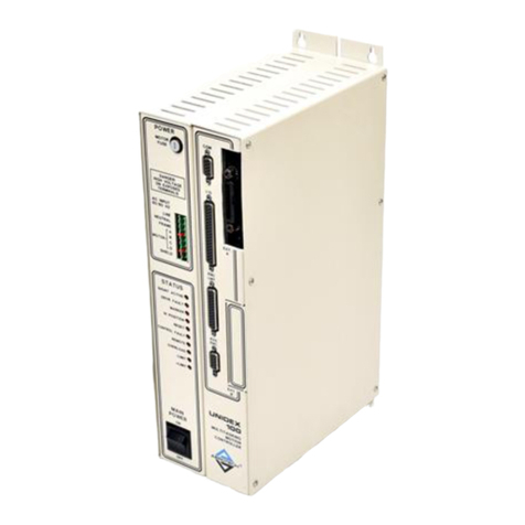
Aerotech UNIDEX U100i User manual
Aerotech
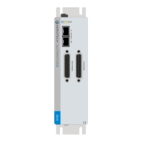
Aerotech Automation1 GI4 Galvo User manual
Aerotech
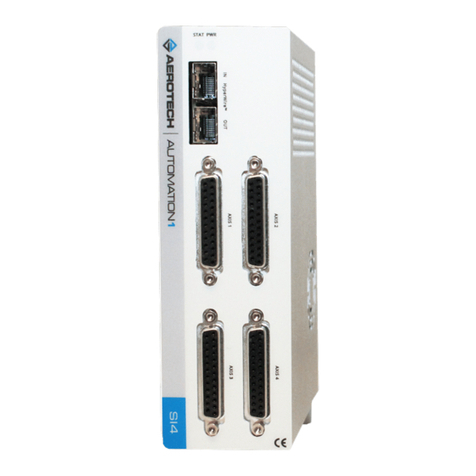
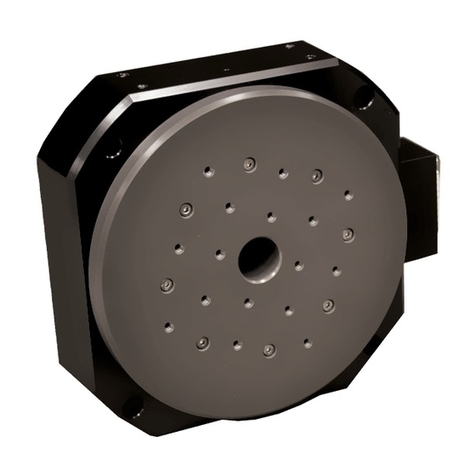
Aerotech Automation1 SI4-2P1 User manual
Aerotech
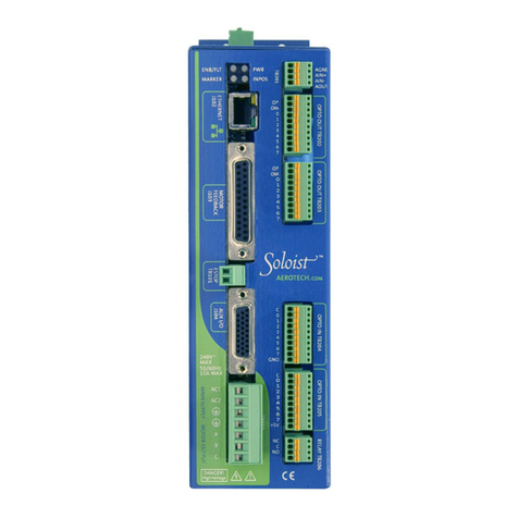
Aerotech ADRS Series User manual
Aerotech
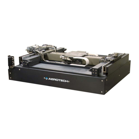
Aerotech SOLOIST User manual
Aerotech
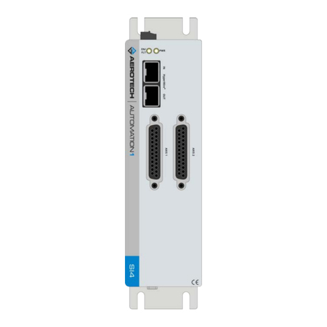
Aerotech PLANAR HD Series User manual
Aerotech
Aerotech Automation1 SI4 Series User manual
Aerotech
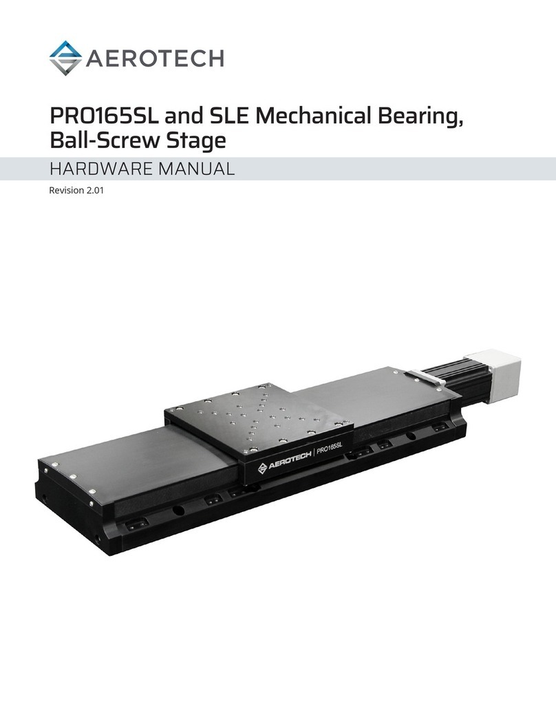
Aerotech PRO165SLE Series User manual
Aerotech
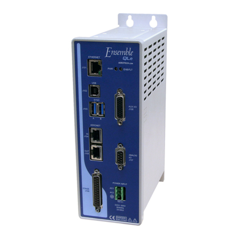
Aerotech Ensemble QL User manual
Aerotech
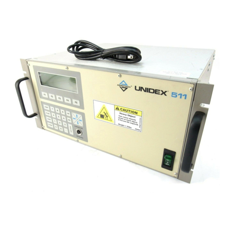
Aerotech UNIDEX 511 User manual
Aerotech
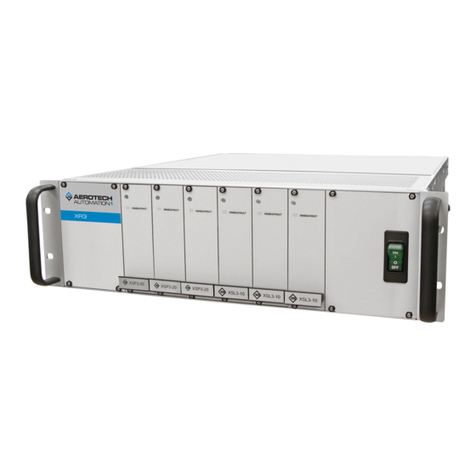
Aerotech XR3 User manual
Aerotech
Aerotech HPe 150 User manual
Aerotech
Aerotech ECO165SL Series User manual

Aerotech
Aerotech A3200 Series User manual
Popular Controllers manuals by other brands

Digiplex
Digiplex DGP-848 Programming guide

YASKAWA
YASKAWA SGM series user manual

Sinope
Sinope Calypso RM3500ZB installation guide

Isimet
Isimet DLA Series Style 2 Installation, Operations, Start-up and Maintenance Instructions

LSIS
LSIS sv-ip5a user manual

Airflow
Airflow Uno hab Installation and operating instructions

