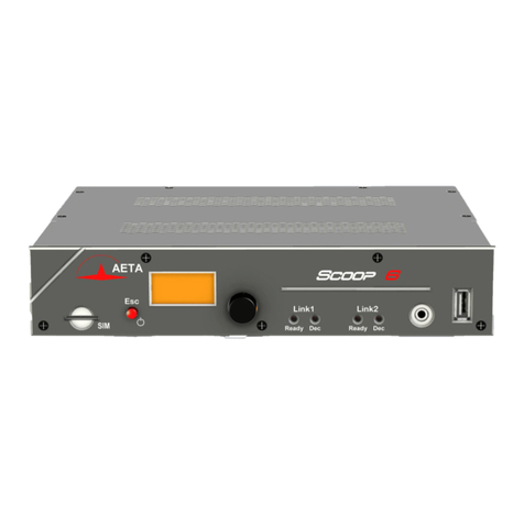
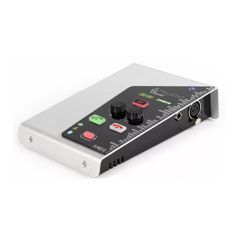
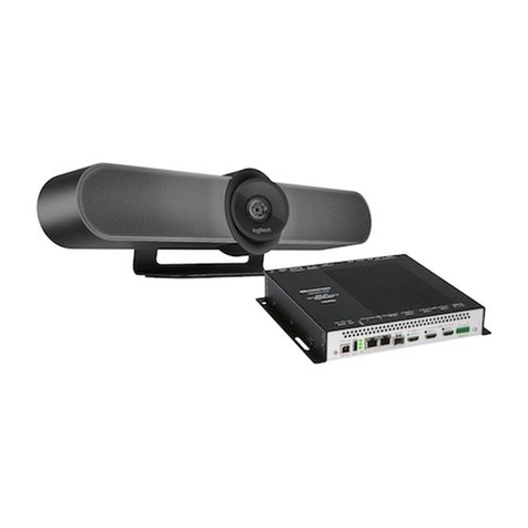
Aeta Audio Systems Scoop5 S-IP User manual

Stereo audio codec for real time audio transmission
User Manual


Scoop5 S-IP - User Manual
Table of contents
1. Presentation –Getting started.......................................................................... 1
1.1. Install and connect Scoop5 S-IP.................................................................................................... 3
1.2. Audio settings............................................................................................................................... 3
1.3. Select and set up network to be used.......................................................................................... 3
2. Functions............................................................................................................ 5
2.1. Transmission interfaces................................................................................................................ 6
2.2. Audio encoding and decoding.................................................................................................... 10
2.3. Audio interfaces ......................................................................................................................... 14
2.4. Auxiliary functions...................................................................................................................... 15
2.5. Supervision and control interface .............................................................................................. 17
3. Operation...........................................................................................................19
3.1. General principles –Control means ........................................................................................... 19
3.2. Physical description of the equipment....................................................................................... 20
3.3. Installation and set up................................................................................................................ 24
3.4. Initial setup of the Ethernet interface........................................................................................ 26
3.5. Managing links............................................................................................................................ 29
3.6. First level maintenance .............................................................................................................. 33
4. Detailed operating mode –Embedded HTML pages......................................36
4.1. Equipment start-up .................................................................................................................... 36
4.2. Accessing the Scoop5 S-IP html pages ....................................................................................... 37
4.3. Principles of operation with html pages .................................................................................... 38
4.4. Detailed presentation of the html pages ................................................................................... 39
4.5. Setting up an IP link.................................................................................................................... 58
4.6. Setting up a link over a leased line............................................................................................. 63
4.7. Management of the configuration profiles................................................................................ 64
4.8. Clearing all settings .................................................................................................................... 64
5. Technical characteristics.................................................................................65
5.1. Characteristics of interfaces....................................................................................................... 65
5.2. Audio performance .................................................................................................................... 72
5.3. Network protocols and ports ..................................................................................................... 74
5.4. Power supply .............................................................................................................................. 75
5.5. Dimensions and weight .............................................................................................................. 75
5.6. Environmental characteristics.................................................................................................... 75
5.7. Options ....................................................................................................................................... 75
5.8. Accessories and related products .............................................................................................. 75
6. Annexes.............................................................................................................76
6.1. Additional information on the algorithms and protocols used.................................................. 76
6.2. Overview of the SIP protocol...................................................................................................... 77

Scoop5 S-IP - User Manual
6.3. Some methods to deal with NAT routers and firewalls ............................................................. 79
6.4. V35 interface adaptation............................................................................................................ 84
6.5. Notice regarding open source code ........................................................................................... 84
7. Index.................................................................................................................. 85

Scoop5 S-IP - User Manual
1
1. Presentation –Getting started
The Scoop5 S-IP codec allows the bi-directional transmission of one or two audio signals with bit rate
reduction, over digital leased lines or IP protocol networks.
The codec includes an Ethernet interface for IP transmission, and X24/X21 interfaces for transmission
over digital leased lines. The unit can be complemented with options, such as for instance a DC power
input.
In IP mode, the codec features easy operation thanks to the use of the SIP and SDP protocols.
For the transmission over IP using the SIP protocol, the unit can be operated in a “double codec” mode.
It behaves in such case as two independent mono codecs, both operating on the same Ethernet
interface.
This chapter gives basic instructions for a quick start. It obviously does not provide all the information
for full control. For comprehensive information one can refer to the rest of this manual:
Chapter 2 describes all the functions and features of the Scoop5 S-IP (but not necessarily with
all the operating modes)
Chapter 3 gives a physical description of the unit, shows its setting up and operation
principles.
Chapter 4 details the html server embedded in Scoop5 S-IP and detailed operating modes.
Chapter 5 provides all the technical characteristics of the Scoop5 S-IP
The annexes bring miscellaneous additional information, including an index you can use to look
for a given information topic.
The following table shows the main features of the product. Functions marked with in this table are
available as options.
Note: this document is relevant for units with firmware version 1.07.
Previous versions have differences in the features and the user interfaces.

2
Scoop5 S-IP - User Manual
Characteristics
Optional
Transmission interfaces
Ethernet/IP transmission interface
Ethernet Interface, 10BaseT / 100BaseT; TCP/IP, UDP/IP, RTP, RTCP protocols
Audio transmission (AoIP) in unicast mode: SIP signalling protocol, SDP, RTP streaming
Double AoIP/SIP codec operating mode
Audio transmission in multicast mode: RTP streaming
Net bit rate 12 to 256 kbit/s (depending on coding algorithm, linear coding excluded)
Leased line transmission interfaces
Two X24/X21/V11/V35 interfaces;
64, 128, 192, or 256 kbit/s over one interface (selectable)
Audio coding algorithms
(audio modes)
G711 (standard AoIP telephony)
G722 SRT, H221
CELP 7 kHz
MPEG Audio Layer II
MPEG AAC-LC , HE-AAC, HE-AAC v2
4 sub-band ADPCM (low latency)
OPUS
Linear L16, L20, L24
Mono
Mono
Mono
Mono, Stereo, Dual mono, Joint stereo
Mono, Stereo
Mono, Stereo
Mono, Stereo
Mono, Stereo
Audio interfaces
Two analog inputs and two analog outputs with adjustable gain
Digital input and output, AES/EBU format
Level display for encoder inputs and decoder outputs
Auxiliary functions (available depending on transmission interface)
Relay transmission: 2 isolated inputs and 2 isolated outputs, 6 non isolated inputs and outputs
Data channel with RS232 serial port, 300 to 9600 bauds
Control and supervision
Status indicators on front panel
Ethernet/IP remote control
Embedded html server
Programmable set-up/dial memories
Remote control serial port, isolated control and status loops
Secondary Ethernet interface for remote control
Table 1 –Main features of the Scoop5 S-IP

Scoop5 S-IP - User Manual
3
1.1. Install and connect Scoop5 S-IP
Plug on a power source: the Scoop5 S-IP automatically starts up. To put it on stand-by or restart
it, press the key (top left corner on the front panel) for at least 3 seconds.
Connect the necessary audio interfaces (details: page 21)
Connect Scoop5 S-IP on the transmission network (details: page 21 and following)
Connect Scoop5 S-IP to the local Ethernet/IP network (if not already done) and pick its IP
address (details in page 26, Initial setup of the Ethernet interface).
From a computer with network access and capable to communicate with the Scoop5 S-IP, open
a web browser and enter the IP address of the Scoop5 S-IP to access its embedded html pages.
To change the language if desired, click the appropriate flag on the top right corner!
For entering pages other than the home page (which is open access), you must enter the login
password. In the “factory setting”, it is blank.
1.2. Audio settings
With factory settings, the active inputs are the analog ones, and clipping level is set at +16 dBu
for both inputs and outputs.
In the Scoop5 S-IP html pages, go to the “Audio” tab and configure the interfaces as required
for the installation.
1.3. Select and set up network to be used
Select network: “NETWORK” tab, then select page “CHANGE NETWORK”. In the proposed choice,
select the desired network (Ethernet, LL). Click “Save” to perform the possible change.
Select the audio coding: “CODING” tab, make settings and click “Save”.
The available choice depends on the transmission network, LL or IP! For more details on coding, see
page 10.
For operating the unit as a “double AoIP codec”, see details in 2.2.2, Double AoIP codec, and in 4.5.5,
Case of the double SIP codec.

4
Scoop5 S-IP - User Manual
1.3.1. Set up an IP link
For links over a public IP network via an access router with NAT1, it is highly recommended
to use a STUN server.
The address of a STUN server can be set in the html page “AOIP PARAMETERS”, via the “NETWORK” tab
(see page 46). In the “STUN Server” field, enter the address of a STUN server (we propose our server
stun.aeta-audio.com, look also the support pages on our web site www.aeta-audio.com). Enable or
disable STUN with the “STUN Mode”checkbox. More details: see page 80.
Go to the “CONNECTIONS” tab.
In the “Connection State” area, “Remote Number” field , enter the remote number to call
(numeric IP address, or SIP URI if a SIP server is used), then click the “Dial” button.
Hang up/release the link using this same button (it becomes “Release” while the link is
established).
When using a SIP server, some data must be entered beforehand using the “AOIP PARAMETERS”
page; for more details, refer to page 46.
The above describes the simplified procedure for setting a call with the SIP protocol; for more details and
especially for using “Direct RTP” or multicast modes, refer to 4.5, Setting up an IP link.
1.3.2. Set up a leased line (LL)
No connection procedure is involved with such link, as it is automatically set (or reset) as soon as the
needed connections are done and the settings are correct on both sides of the link.
See in this manual on page 49 for configuration details.
1Network Address Translation, applied in most cases by such routers

Scoop5 S-IP - User Manual
5
2. Functions
The following synoptic diagram shows the basic functions of the equipment.
Figure 1 –Functional diagram of the equipment
The audio signals to be transmitted are converted (when needed) to digital format, then the encoding
function reduces the bit rate, using a selectable algorithm; the resulting bit flow is sent to one of the
available transmission interfaces: Ethernet interface, permanent link data interfaces (X21/X24/V35)...
The transmission interface functional block also extracts compressed data coming from the network and
sends them to a decoding block that reproduces uncompressed audio data. Last, the audio signals are
output to both digital and analogue outputs.
In addition to the main task of transmitting an audio programme, the Scoop5 S-IP can also transmit
auxiliary information, usually by embedding them inside the transmitted audio streams.
Supervision and controlling the unit is performed using various remote control interfaces.
Audio
inputs
Audio
outputs
Conversion
Conversion
Encoding
Decoding
Transmission
Interfaces
Control Interfaces
Network
Supervision
Auxiliary Functions
RS-232 / Relays / GPIO

6
Scoop5 S-IP - User Manual
2.1. Transmission interfaces
The Scoop5 S-IP features an Ethernet interface for IP protocol networks, and leased line transmission
interfaces (X24/V11).
2.1.1. Ethernet/IP interface
The IP interface is a 10BaseT/100BaseT Ethernet interface allowing transmission of the audio
programmes in a wide range of possible bit rates. The audio stream is always transported under the
RTP/UDP protocol.
IP unicast mode
The most classical transmission mode is unicast: audio connection with one remote device, generally
bidirectional. This mode can be used on all types of networks links, LAN or WAN, including links via
Internet. The Scoop5 S-IP implements the SIP protocol, which allows it to interoperate with IP phones
and other SIP compatible audio codecs, in a way similar to ISDN or POTS connections. This protocol is
also required by the “N/ACIP” recommendation (EBU Tech3326). Links can be set up in two ways:
“Peer to peer” connection between two compatible units
Use of a SIP proxy server to set up the link, or a SIP PBX
Details about the SIP protocols can be found in the annex (see 6.2, Overview of the SIP protocol).
It is also possible to operate in a “Direct RTP” mode, without using the SIP protocol. This operation
mode can be used for interoperation with devices that do not support SIP, or for overcoming possible
network blocking that would specifically affect the SIP protocol.

Scoop5 S-IP - User Manual
7
Available audio coding algorithms
The audio coding algorithm can be selected depending on the required quality and the available
network bandwidth. The following algorithms are currently available:
Codec
Bit rate
(coding)
Bit rate
(total)1
Audio
bandwidth
Typical use, main features
G711
64 kbit/s
86 kbit/s
3 kHz
Voice, telephony
Compatible with IP phones
CELP
24 kbit/s
28.5 kbit/s
7 kHz
Suitable for high quality speech;
Low network bandwidth consumption
G722
64 kbit/s
86 kbit/s
7 kHz
High quality speech.
Compatible with some IP phones.
MPEG Layer II
64 to 256
kbit/s
73 to 275
kbit/s
Up to
20 kHz
Highest quality, suitable for speech and music
MPEG AAC-LC
16 to 256
kbit/s
30 to 277
kbit/s
Up to
20 kHz
Low bit rate, suitable for speech and music
MPEG HE-AAC and
HE-AAC v2
16 to 128
kbit/s
23 to 139
kbit/s
Up to
20 kHz
Very low bit rate, suitable for speech and music
4SB ADPCM
128 or 256
kbit/s
173 or 301
kbit/s
15 kHz
Low latency, suitable for speech and music
OPUS
12 to 256
kbit/s
28 to 272
kbit/s
Up to
20 kHz
Low bit rate and low latency, suitable for
speech and music
Linear L16/L20/L24
512 to 2304
kbit/s
592 to 2384
kbit/s
Up to
20 kHz
Best quality, very low latency
Table 2 –Overview of algorithms available in IP mode
IP multicast mode
The multicast mode allows an encoder device to transmit an audio programme to several decoders by
sending a single encoded stream to a multicast group address. The link is unidirectional by nature. This
mode can be used on a local area network, and on larger private networks that can manage the
multicast mode. On the other hand, Internet cannot support this routing mode.
In this mode, the Scoop5 S-IP uses the RTP protocol to manage the audio stream, like in the unicast
mode, but the SIP protocol is not applicable here; instead a proprietary signalling system is used. As the
link is unidirectional, the unit has to be set either as a “sender” in order to encode and transmit the
audio stream to the selected group address, or as a “receiver” to receive and decode such stream
coming from a “sender” device.
The audio coding algorithm can be selected with just the same capability as for the unicast mode
described above.
SIP and SDP protocols
The SIP protocol is a signalling protocol, used for IP connections, which allows the Scoop5 S-IP to
interoperate with IP phones and other SIP compatible audio codecs, in a way similar to ISDN or POTS
connections. Details about the SIP protocols can be found in the annex (refer to 6.2, Overview of the SIP
protocol).
1Informative value; higher than the “net” encoded audio bit rate because of the protocol overhead

8
Scoop5 S-IP - User Manual
One significant advantage is the inclusion of SDP, a protocol which allows the connecting devices to
automatically negotiate and agree on the coding profile to use. Thanks to this system, it is not necessary
to set the units in the same way before setting up a connection. Moreover, the calling party needs not
know how the remote unit is configured before initiating a link.
Note: the SIP protocol does not mandatorily imply the use of a server. Codecs can set up point-to-
point links using this protocol, and benefit from some its advantages.
Double SIP codec
This operation mode is available as an option.
In the unicast mode with SIP, the Scoop5 S-IP can be uses as two independent mono codecs. Each of
these is then a mono SIP codec that can set an audio link in two ways:
Direct “peer to peer”connection with a compatible remote unit.
Use of a SIP proxy server to set up the link, or a SIP PBX. In such use case, each codec has got its
own registration.
The available audio coding algorithms are a subset of those of the “standard” mode (single codec): see
“2.2.2”, page 11.
Packet duplication
Scoop5 S-IP also proposes an RTP transmission mode with enhanced reliability, using packet replication.
When enabling this mode, every packet is transmitted twice; with such system a lost packet has no
effect since the receiver still gets the other copy of the packet. In this way, stable links can be obtained
even with a high packet loss rate. Of course, as a disadvantage the bit rate is double; you must make
sure this stays compatible with the transmission medium.
Remote control via IP
In addition, the Ethernet interface can be used for configuring or remote controlling the unit, with two
control methods:
Scoop5 S-IP provides html pages which allow to get complete control over the unit using a web
browser, via port 80 (default port for http protocol). See in chapter 4 the detailed operating
mode.
The supervision software Scoop Manager from AETA can remote control the Scoop5 S-IP via a
TCP/IP connection on port 7001.
TCP port 6000 can be used for “command line”control, suitable for codec supervision software
such as Scoop Manager, Codec Live, MDC.Net, etc.

Scoop5 S-IP - User Manual
9
2.1.2. Leased line interfaces
For transmission over leased lines, the codec includes two X24/V11 ports which can run at 64 kbit/s, 128
kbit/s, 192 kbit/s, 256 kbit/s and 384 kbit/s bit rates.
Only one X24/V11 port is used, selectable among the two physical interfaces. The other, however, send
the same data as the active one, and it can be used e.g. for a redundant link.
For “leased line” transmission, the codec synchronises on the network clock provided by the X24/V11
interface. If no suitable clock is present, the system folds back to an internal clock.
2.1.3. Managing calls
One of the transmission interfaces is selected as the default interface on the Scoop5 S-IP.
If this is the LL interface (leased line), this is a permanent connection.
Otherwise, for the Ethernet/IP interface, the audio transmission implies a link/session setup phase.
Either the link is initiated by the unit itself, or rather the operator of the Scoop5 S-IP: call to a
remote destination.
Or the link results from a request from a remote unit. Such call can be received and processed
as long as the Ethernet interface is connected and is the default interface.
2.1.4. Securing a link with a backup connection
When a fixed link (LL) is used, it is possible to use another network access in order to set a temporary
backup link in case the nominal LL link fails. The unit will then switch to a backup mode (IP), and provide
the audio transmission via the backup network access. More precisely, on one end of the link the codec
will switch to the backup mode and “call” its counterpart via the IP network. On the other end the unit
will switch to the backup mode when it receives the call on its IP interface. The operating mode and
configuration for this backup feature are detailed further in following sections (3.5.4, Setting up a
backup link).

10
Scoop5 S-IP - User Manual
2.2. Audio encoding and decoding
Scoop5 S-IP features a wide range of coding algorithms. Their availability depends on the transmission
network used. Besides, the MPEG family algorithms feature a large configuration flexibility.
2.2.1. Single codec
In this mode, the selected network interface (Ethernet/IP or LL) is used to set a link with a single remote
device. The table below synthetically describes the capabilities with the two transmission media:
Table 3 –Available coding depending on network
16 24 32 48 LL Ethernet
G711 Mono 64
CELP Mono 24
G722 Mono 64
G722-H221 Mono 64
4SB ADPCM Mono 128
4SB ADPCM Stéréo 256
MPEG L2 M / S 64
MPEG L2 M / S 128
MPEG L2 M / S 192
MPEG L2 Stereo 256
MPEG L2 Stereo 384
AAC-LC M / S
16 56
AAC-LC M / S 64
AAC-LC M / S 96
AAC-LC M / S 128
AAC-LC M / S 192
AAC-LC Stereo 256
HE-AAC M / S
16 56
HE-AAC M / S 64
HE-AAC Stereo 96
HE-AAC Stereo 128
HE-AAC v2 Stereo
16 56
HE-AAC v2 Stereo 64
OPUS M / S
12 256
Linear L16 Mono 512 / 768
Linear L16 Stereo 1024 / 1536
Linear L20 Mono 640 / 960
Linear L20 Stereo 1280 / 1920
Linear L24 Mono 768 / 1152
Linear L24 Stereo 1536 / 2304
Possible audio bandwidth:
3 kHz 7 kHz
15 kHz 20 kHz
Network
Codec
Audio
channel
Frequency (kHz)
Bit rate
(kbit/s)

Scoop5 S-IP - User Manual
11
2.2.2. Double AoIP codec
This mode is available as an option, for the transmission over an Ethernet access interface and with the
SIP protocol.
In this mode, two AoIP links can be set simultaneously, possibly with two separate remote devices.
Either link is a mono link. The table below shows the capabilities for each link:
Table 4 –Available coding in double AoIP codec mode
2.2.3. Details about the coding algorithms
The following chapters bring some precisions about the important features of the various algorithms
and protocols available.
G711 coding
Application: telephony, coordination. Low latency.
G711 is the standard coding used for voice transmission on public telephone networks, and features 300
to 3400 Hz audio bandwidth. This algorithm is typically used for links over IP networks with IP
telephones or VoIP gateways.
G711 is available only for IP transmission (single or double AoIP codec).
CELP coding
Application: commentaries, coordination. Low capacity transmission channels
This algorithm operates in mono for a net nominal bit rate of 24 kbit/s, and provides 7 kHz bandwidth
and a quality close to G722 for a much lower bit rate.
CELP is available only for IP transmission (single AoIP codec).
816 48
G711 64
G722 64
MPEG L2 64
MPEG L2 128
AAC-LC 64
AAC-LC 128
HE-AAC 64
HE-AAC 128
OPUS
12 192
Codec
Frequency (kHz)
Net bit rate
(kbit/s)

12
Scoop5 S-IP - User Manual
G722 coding
Application: commentaries, coordination. Low latency.
This mono coding algorithm at a 64 kbit/s bit rate is a reference for commentaries, and features a 50-
7000 Hz bandwidth.
It is available for LL or IP networks (single or double AoIP codec).
For leased lines, two synchronisation modes are possible:
“Statistical recovery” byte synchronisation method (alias SRT);
H221 synchronisation; in this case, 1.6 kbit/s from the compressed data are used for this;
H221 synchronisation is highly recommended when possible, as it features higher reliability and faster
recovery time, while degradation (because of the bit rate used for framing) is minimal.
No specific synchronisation is required for the IP mode.
4SB ADPCM coding
Application: commentaries, mono or stereo music. Low latency.
4SB ADPCM operates either in mono at a 128 kbit/s rate, or in stereo at 256 kbit/s, for a 15 kHz
bandwidth. It features a very low latency which makes it very interesting for live duplex transmission. It
also has the advantage to be very little sensitive to tandem coding.
4SB ADPCM is available for LL or IP (single AoIP codec). However it is not recommended for low quality
IP networks, because it requires a high bit rate and it is highly sensitive to packet losses.
MPEG Audio Layer 2 coding
Application: mono or stereo music, high quality.
As shown on Table 3, this coding algorithm features a maximum flexibility, with many variations for bit
rate, mono or stereo channel mode, sampling rates...
The two channel modes exist in three variations:
Stereo: coding of each channel stays independent
Dual mono: coding is similar to the previous case, but this choice applies to channel with no
acoustic relationship, e.g. two languages for commentaries
Joint stereo: applies to stereo programme, but here the encoder exploits the interchannel
correlation for improved coding. To be used only for a stereo programme
The 16 and 24 kHz sampling rates feature a moderate bandwidth (respectively 7 kHz and 10 kHz) and are
rather useful for commentaries.
The latency is rather high with these sampling rates.
MPEG L2 is available for LL or IP networks (single or double AoIP codec).
In leased line mode, an optional protection against transmission errors (FEC) is also available, of Reed-
Solomon type.

Scoop5 S-IP - User Manual
13
MPEG AAC algorithms
Application: mono or stereo music, Low capacity transmission channels.
These (optional) algorithms feature a very high compression ratio, for a given audio quality, compared
to Layer 2. They can operate at a sampling rate of 32 or 48 kHz, and several bit rates: 16, 20, 24, 32, 40,
48, 56, 64, 96, 128, 192, 256 kbit/s. Three coding variations are available:
MPEG AAC-LC (“Low Complexity”): lower compression than other variations, but lower latency.
MPEG HE-AAC (“High Efficiency” AAC): higher compression, and the bit rate is limited to
128 kbit/s for this variation.
MPEG HE-AAC v2 (“High Efficiency” AAC version 2): compared to the above, this coding further
enhances the performance for a stereo program (not available for mono). The bit rate is limited
to 128 kbit/s for this variation.
AAC codecs are available for IP networks only (single or double AoIP codec).
OPUS coding
Application mono or stereo music, low capacity transmission channels. Moderate latency.
Opus is an open source coding algorithm (under BSD license), described by RFC6716 from the IETF. Like
MPEG coding algorithms, it is a wide band audio codec, but it features distinctive characteristics:
Low latency; the algorithmic delay of Opus is very low compared to MPEG coding (Layer 2, AAC,
HE-AAC...).
Adaptability: Opus features many parameters influencing its performance, but it is possible to
adapt them automatically depending on the external constraints and the signal characteristics.
In the Scoop5 S-IP, the configuration stays very simple: the user just imposes the audio channel
format (mono/stereo) and the desired bit rate, and the codec automatically adjusts the other
parameters (for instance the audio bandwidth).
Capacity to apply changes “on the fly”: the coding allows changing its operation parameters on
the fly, with no interruption and no artefacts when switching. In this way the bit rate can be
changed during the link on the Scoop5 S-IP, without any audio noise or dropout.
In addition, when the remote device is another AETA codec, it will automatically apply the same
bit rate change to the stream it is transmitting.
Opus coding is only available for IP networks (single or double AoIP codec).
Linear coding
Application mono or stereo music, transmission media with very high capacity and reliability.
The linear coding is in fact the absence of coding/compression; the audio data are transmitted without
information loss and with no bit rate reduction. Obviously this implies a very high bit rate; therefore
linear coding is only usable over an IP network, and with a very high bandwidth and a very good quality
of service, such as a local area network or a high reliability private WAN.
The coding features three variations L16, L20 and L24, corresponding respectively to a sample resolution
of 16 bits, 20 bits, or 24 bits for the transmitted audio. With each variation it is possible to select a
sampling frequency of 32 or 48 kHz, and a mono or stereo channel mode.
The linear coding is only available for IP networks (single AoIP codec).

14
Scoop5 S-IP - User Manual
2.3. Audio interfaces
2.3.1. Analog interfaces
The analogue inputs and outputs are balanced, and the input and output gains are adjustable.
The input to the encoder is selectable between the digital audio input and the stereo analogue input.
The output from the decoder is always provided on the stereo analogue output.
The sampling frequency of the analogue digital converters is automatically set depending on the
coding algorithm used for transmission.
2.3.2. Digital interfaces
The equipment also provides digital audio inputs/outputs in AES/EBU format.
The input to the encoder is selectable between the digital audio input and the stereo analogue input.
The output from the decoder is always provided both on the digital output and the stereo analogue
output.
The digital audio interfaces are usually locked to the digital audio input (“genlock” mode), but
alternatively they can be synchronised to the internal clock reference of the codec (mode called
“Master”).
Sampling rate conversion is automatically performed, whenever needed, depending on the coding
algorithm used for transmission.
As an important consequence, the selection or value of the sampling frequency of the AES/EBU
input/output is completely independent of the sampling frequency of the compression algorithm.
One should also be aware that the various audio settings have no relationship with those for the other
side of the link (the remote codec), whatever they are: selection of analog or digital source, sampling,
rate of AES interfaces, etc. This configuration is only relevant for the local installation.
2.3.3. Audio monitoring
The audio program level is measured at the audio input (before encoding) and at the audio output (after
decoding the received signal). These levels are displayed on some html pages of the unit.
Note: as the audio output is monitored immediately after decoding, this monitoring position is not
sensitive to the possible activation of the audio test loop (see further the chapter about test loops),
contrarily to the physical audio outputs (both analog and digital).

Scoop5 S-IP - User Manual
15
2.4. Auxiliary functions
The main function of the Scoop5 S-IP is the transmission of one or two main audio programmes, but it
also provides auxiliary functions for transmitting data or additional signals, inside the same stream (or,
more generally, the same session).
These features are only compatible with AETA products, because they are not inside the scope of
independent standards.
The availability of these functions depends on the coding algorithms, and on the transmission network.
The following tables show these capabilities for the various networks.
Table 5 –Auxiliary functions: over leased lines
Table 6 –Auxiliary functions: over IP networks (SIP)
The auxiliary functions are not available in double AoIP mode or in “Direct RTP” mode.
Isolated GPIO 300 1200 2400 4800 9600
G711
CELP
G722-SRT
G722-H221
4SB ADPCM X
MPEG L2
AAC-LC
HE-AAC
HE-AAC v2
OPUS
L16, L20, L24
X = exclusive (only one function at a time)
Codec
Relays
Data (bauds)
X
Isolated GPIO 300 1200 2400 4800 9600
G711
CELP
G722
G722-H221
4SB ADPCM
MPEG L2
AAC-LC
HE-AAC
HE-AAC v2
OPUS
L16, L20, L24
Codec
Relays
Data (bauds)

16
Scoop5 S-IP - User Manual
2.4.1. Transmission of isolated relays
When this function is activated, the codec transmits to the remote unit the status of two isolated
current loops. The remote unit then opens or closes relay contacts according to the transmitted status.
Conversely, as the function is bi-directional, the codec activates its two relays (“dry” isolated contacts)
depending on the status of the two current loops on the remote unit.
For transmission over IP (single SIP/AoIP codec), this feature is always available whatever the coding
algorithm (except for linear coding L16, L20, L24). For the LL mode, availability depends on the
algorithm: see above tables.
With G722 or 4SB ADPCM, relay transmission cannot be used at the same time as another auxiliary
function (see tables).
A typical application is the transmission of “on air”signals; a contact closure can be used for instance to
light up an indicator or switch on other equipment.
2.4.2. Transmission of GPIO
For IP transmission (single SIP/AoIP codec), Scoop5 S-IP also allows, in the same way as the two isolated
relays, to transmit 6 additional binary signals, routed to “GPIO” interfaces, which are not isolated. This
feature is available whatever the coding algorithm (except for linear coding L16, L20, L24).
2.4.3. Data channel
This function is not available in IP transmission mode.
In leased line mode, a bi-directional data channel can be transmitted along with the compressed audio
signals, by reserving a fraction of the transmitted bit rate. The equipment includes a serial asynchronous
port for this purpose. The data are transparently transmitted end-to-end; hardware signalling is not
available.
Availability depends on the coding algorithm, as well as the max possible baud rate: see above tables.
With G722 or 4SB ADPCM, this data channel cannot be used at the same time as another auxiliary
function (see tables).
A typical application is the transmission of data related to the RDS.
Table of contents
Other Aeta Audio Systems Conference System manuals
