Aeta Audio Systems SCOOP STUDIO User manual

Specifications are subject to change without notice 55000101-A © 2016
Getting started
www.aeta-audio.com

2
FRONT PANEL AND INDICATORS
1. USB socket (type A) for connecting a memory key,
usable for a recovery configuration.
2. Power indicator: green when the unit is powered.
3. “Ready”indicator: this LED goes red at startup time or in
case of an alarm, and goes green when the unit is ready
for operation. The LED also blinks red if SIP registration is
active but fails.
4. Decoder status: this LED is off when idle, green when a
link is established, red in case of a sync loss of the
decoder.
5. Signal presence, left input: green for a normal audio
level, orange and then red in case of an overload.
6. Signal presence, right input: green for a normal audio
level, orange and then red in case of an overload.
7. Reset button: allows to restart the unit (use a sharp
object, such as a pen).
8. Area for marking: available for writing an identification
text or sticking a label.
2 3 4 5 6 71
8

3
REAR SIDE AND CONNECTIONS
Analog version (µScoop A)
Digital version (µScoop D)
9. MAC Address of the Ethernet interface.
10. DC power: 2.1 mm jack for an external power supply 10
to 16 V, 0.5 A maximum.
11. Ethernet / PoE : 10/100Mbit/s Ethernet interface , with
“Power over Ethernet” capability.
12. GPIO : RJ11 socket with 2 relays and 2 isolated contacts.
Pinout :
Contact
Function
Direction
1
Ground
+ GPI 1&2 common
2
Relays/GPO 1&2 common
Output
3
Relay/GPO 2
Output
4
Relay/GPO 1
Output
5
GPI 2
Input
6
GPI 1
Input
13. Line output, right: 3-pin male XLR, electronically
balanced, adjustable level +4 dBu to +22 dBu.
14. Line output, left: 3-pin male XLR, electronically balanced,
adjustable level +4 dBu to +22 dBu
15. Line input, right: 3-pin female XLR, electronically
balanced, clipping level adjustable +4 dBu to +22 dBu.
16. Line input, left: 3-pin female XLR, electronically balanced,
clipping level adjustable +4 dBu to +22 dBu.
17. AES/EBU output: stereo output, AES3-2009 format.
18. AES/EBU input: stereo input, AES3-2009 format.
11 12 13 14 15 1610
9
11 12 17 1810
9

4
INTRODUCTION
We advise you to read this guide first to help you get familiar with
the µScoop in a short time. For more detailed information, please
consult the full user manual on our web site: www.aeta-audio.com
For this guide, we assume that the basic principles are known and
that you have already connected audio equipment to the µScoop.
µScoop is a full-duplex mono/stereo audio codec, designed for
performing audio over IP (AoIP) links via Ethernet access. µScoop
comes in two versions:
Analog version µScoop A, with two analog audio inputs and
two analog audio outputs.
Digital version µScoop D, with one AES input and one AES
output.
Various compression algorithms are available: linear 16/20/24 bits,
G711, G722, MPEG Layer 2, AAC including HE-AAC and HE-AAC v2
variations, and above all OPUS coding.
The audio program is transported using the RTP/UDP protocol. The
audio link can be set up with three possible protocols:
SIP (Session Initiation Protocol): this protocol eases the
configuration of the codecs to be linked, especially (but not
necessarily) when using a SIP server on the network. µScoop is
also compliant with the EBU Tech3326 recommendation, also
known as « N/ACIP ».
“Direct RTP”mode: basic mode with no signaling. This mode is
compatible with devices that do not support SIP or N/ACIP, but
it requires dealing directly with all the parameters of the
codecs to be linked.
Multicast: usable on private networks that support it, the
multicast mode allows distributing efficiently a program
towards several destinations on the network.
µScoop can be integrated in a 19” rack, with a size of 1/3 of a rack
unit.
µScoop can be configured and controlled by remote through its
Ethernet/IP interface. We describe here the most common
management interface, which is the embedded HTML server (aka
“web pages”).
This guide applies to units with firmware version 1.02 or newer.

5
SETTING UP
µScoop can be operated under an ambient temperature of 0° to 45°C
(32°F to 113°F).
Installation in a 19’’ rack
A rack mount tray is available for integrating the units in a rack.
Mount 1 to 3 units in the tray, using the provided screws (do not use
longer screws!). Then set the assembled tray into a 1U space of the
rack.
For a suitable heat dissipation, leave some free space
(10 mm at least) at the top and bottom of the assembled
tray.
Powering
µScoop can be powered in two ways: either by using an external DC
supply, or by connecting to a switch or router capable to provide
power through the Ethernet link (PoE, Power over Ethernet).
In the former case, you can use the provided power adapter
(GST25B12-P1J), or another suitable DC power supply, plugged on
the [10] socket. µScoop runs from a nominal 12 V, but it can run
from a 10 to 16 V voltage, with a maximum consumption of 0.5 A
In the latter case, the Ethernet connection on the PoE switch/router
also provides the unit its power supply. µScoop is detected by a PoE
source as a class 2 powered device.
It is possible to use both power sources at the same time ; µScoop
draws current from the PoE source as a priority, as long as the
voltage of the DC source is less than 13.5 V.
Connection to the IP network
Connect the Ethernet interface (socket [11]) to the network. The
LEDs on the socket show the network presence and possible activity.
For operating the µScoop, first it must be assigned a valid IP address.
Then this address can be used for configuring the device.
Out from the factory, µScoop is set for using a DHCP server. Once
the unit is connected to the network and switched on, there are two
alternatives:
Either a DHCP is indeed present on the network the µScoop is
connected to: in this case the server provides the unit the
parameters it must apply.
Or no DHCP server is available on the network: in this case the
µScoop automatically applies a “link-local” IP address, with a
169.254.x.x pattern. This address can be used to initially access
the µScoop, and then configure it as needed with parameters
more suitable for the network in use.
At this stage, there are several ways to find out the IP address of the
µScoop:
The network administrator can program an address
reservation for the µScoop on the DHCP server;
The network administrator can use a tool for
identifying/detecting the µScoop (for example by consulting
the table of address leases in the DHCP server).
The AetaScan tool can scan you local area network, enumerate
the AETA codecs and display a list with their MAC and IP
addresses. You can download it from the AETA web site
(www.aeta-audio.com, see the µScoop product page).
AetaScan is a Java script Java which runs on every OS.
In every case, the MAC address of the µScoop is useful to identify it; it
is recalled on the sticker [9] on the rear side of the device.

6
Access to the management interface, “web pages”
Once the IP address is known, enter it in an HTML browser, on a computer connected to the same LAN as the µScoop (all current browsers are
suitable). The home page of the µScoop then appears:
If the automatically set address is not
suitable for the subsequent operation, the
first thing to do is to configure “statically”
the addressing with suitable parameters
provided by the network administrator:
Click « Login » on the top right corner
of the page;
Select “NETWORK”in the menu bar
and click on “ETHERNET PARAMETERS”;
Select the “Manual” mode, enter the
needed parameters and click “Save”;
At this moment you will lose control
because of the IP address change!
Enter now in the browser’s address
field the newly set IP address and
check that the change has been
performed successfully.
You can find more details on page 14.

7
ESTABLISHING A LINK
Establishing a link is roughly like making a phone call: a “caller”
device initiates a link by soliciting a “called” unit.
Switching µScoop on/off
The unit starts up as soon as a power source (whichever it is) is
connected.
To switch off the unit you must disconnect both power sources
(external DC and PoE).
Open the management interface
On a computer connected to the same LAN as the µScoop, enter its
IP address in an HTML browser, as shown on the previous page. If
necessary, click the flag corresponding to the language you prefer
for the interface.
Click “Login”on the top right corner to access the device
configuration. With factory settings or after a full reset, the
password for this access is empty. Otherwise enter here the
password.
Select the coding algorithm
If you want the unit to receive a call (or connection request) with the
SIP protocol, you can skip this step, and go directly to “Preparation:
for the SIP protocol”) further in this guide.
Click the “CODING”tab: the displayed page includes an “ALGORITHM”
frame. Use the drop down lists and set up the µScoop as needed.
Lastly click on “Save”.
For details about the settings on this page, refer further to
“CODING”tab, page 16.
Preparation: for the SIP protocol
On the menu bar select “NETWORK” and click on “AOIP PARAMETERS”.
In the “PROTOCOL”frame, as default protocol select “SIP”. Lastly click
“Save”.
If you want the µScoop to be able to receive calls with the SIP
protocol, make sure that “SIP Accept Calls” is checked in the “SIP”
frame.
If you use a SIP server for the links: enter in the “SIP” frame the data
of the SIP account allocated to the unit, and check the “SIP
registration” checkbox. Lastly click “Save” at the bottom of the “SIP”
frame. Check on the home page (“STATUS“ tab) that the µScoop is
successfully registered on the server. In addition the “Ready” LED [3]
blinks red if the SIP registration fails.
For a link over the Internet via an access router with
NAT, it is recommended to use a STUN server. In the
“STUN”frame, enter the address of a public STUN
server1(IP address or domain name), and check the
“STUN Mode”box.
Verification: you can see on the home page new
information “Public IP”and “NAT Type”, as detected
thanks to STUN.
For details about the settings on this page “AOIP PARAMETERS”,
refer further to “AOIP PARAMETERS” page (“NETWORK ” tab), p. 13.
1You can for instance use the AETA server : stun.aeta-audio.com

8
Preparation: for using the “Direct RTP”mode
On the menu bar select “NETWORK” and click on “AOIP PARAMETERS”.
In the “PROTOCOL”frame, as default protocol select “Direct RTP”.
Click “Save”.
If you want the µScoop to be able to receive calls in this mode, make
sure that “Accept Calls” is checked in the “DIRECT RTP” frame. Read
(or edit) the RTP port number in this frame, as the “caller” unit must
specify this port in order to establish a link.
For details about the settings on this page “AOIP PARAMETERS”,
refer further to page 13.
Preparation: for a multicast link
On the menu bar select “NETWORK” and click on “AOIP PARAMETERS”.
In the “PROTOCOL”frame, as default protocol select “Multicast”. Click
“Save”.
Multicast is essentially a unidirectional protocol, where a
source/transmitter device sends a media stream to several
receivers. In the “MULTICAST” frame, select the “Multicast Mode” as
needed:
1. “TX”so that the unit is sender of an audio stream towards
a multicast group.
2. “RX” so that the unit can be a receiver of a multicast audio
stream.
Click “Save“.
For details about the settings on this page “AOIP PARAMETERS”,
refer further to page 13.
Make a call / establish a link
Click the “CONNECTIONS”tab: the “CONNECTION STATE”frame recalls the
preselected coding configuration. Enter in the “Remote Number”
field the call destination: either the IP address (numeric or URL) of
the remote codec, or its SIP identifier (URI).
For an IP address, if a port number must be specified (other than the
default value), add “:” and the port number, as in the example:
192.168.1.35:9000
Click “Dial” to trigger the call. The “Status” field monitors the call
progress and the establishment of the link.
The “Dec” LED [4] on the front panel goes green when the decoder is
synchronized. The quality meters on the html page monitor the
quality in real time in both directions (in the transmit direction, this
depends on the capability of the remote codec).
Specificity of a multicast link: the address you enter in the
Number field is a multicast group address. In addition, you must
launch a “call” on each device that must receive the multicast
program.
Receive a call (SIP or direct RTP)
You have nothing special to do; the link is initiated by the “caller”
codec. The µScoop which receives the call automatically “unhooks”
and establishes the link. In the case of the SIP protocol, it directly
negotiates the coding parameters with the remote caller unit.
In the Direct RTP case, the link will fail if both devices are not
configured the same way (audio coding, mono/stereo mode, bit
rate…).
The “CONNECTION STATE”frame of the home page (“STATUS” tab)
monitors the call progress and the establishment of the link. The
“Dec” LED [4] on the front panel goes green when the decoder is

9
synchronized. The quality meters on the html page monitor the
quality in real time in both directions (in the transmit direction, this
depends on the capability of the remote codec).
Adjust the bit rate
If the link is set using the Opus coding and the SIP protocol, you can
adjust the transmission bit rate during an audio connection.
During such connection, a “CONNECTION PARAMETERS” frame appears in
the “CONNECTIONS” tab. It recalls the current transmission bit rate.
You can change it on the fly, without any dropout or undesired noise
in the transmitted signal.
Click the “Send” button to actually apply the new bit rate. If the
link is set with another AETA product, the bit rate also changes
on the stream received from the remote codec.
Hang up / release a link
Click on the « Release » button (“CONNECTION STATE” frame of the
“CONNECTIONS” tab).
Redial
To recall easily the last destination called, in the “CONNECTIONS” tab
click the arrow at the right of the “Remote Number” field and select
the number on top of the list. Click “Dial” to launch the call.
In a similar way, you can see a list of the last calls and pick one
for a quick recall.
Use the directory (Call profiles)
If call profiles are recorded in the µScoop, you can use them to
establish a link quickly.
in the “CONNECTIONS” tab, select the desired call profile in the “CALL
PROFILES” frame: the corresponding coding configuration is displayed
in the “CONNECTION STATE” frame. Click on the “Dial” button to trigger
the link immediately.
However, make sure that the default protocol (SIP, Direct RTP or
Multicast) is suitable for the called destination.
To create a call profile, select “PROFILES” in the menu bar and click
“CALL PROFILES”. In the “PARAMETERS” frame edit the adequate
parameters for the link with the remote unit, including the IP
address or identifier on a SIP server. Click “Create new” and enter a
name for this new profile.
You can also edit call profiles, or import/export profiles from/to
your computer: see further on page 11 and page 20.
10
PRESENTATION OF THE MANAGEMENT INTERFACE PAGES
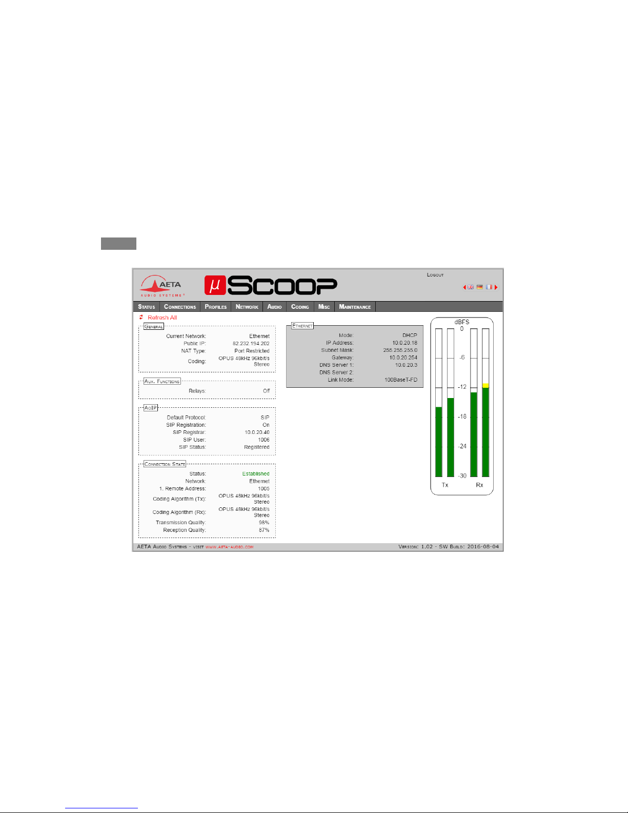
Home page “STATUS”
This page is always accessible unconditionally (no login needed), and provides an overview of the µScoop status.
Note: some information data visible on this screen copy are available depending on the context.

11
“CONNECTIONS” page
“CALL PROFILES” page (“PROFILES”tab)
This frame only shows up
with OPUS coding

12
“PRESETS” page (“PROFILES”tab)
Some use cases for the Presets:
Using more than one SIP server and/or account: the preset allows to switch quickly and without error from one account to another.
Changing the usage context (with or without the SIP protocol, for example).

13
“AOIP PARAMETERS” page (“NETWORK ” tab)
Notes about parameters on this page:
STUN: using STUN is recommended for a SIP
link via an access router with NAT. The public
address and type of NAT are detected and
displayed on the STATUS home page (see
p. 10).
Default Protocol: the one used for an
outgoing call.
SIP-Registrar: IP address or domain name. To
specify a port other than the standard 5060,
add “:” and port number, as in the following
example: sip.aeta-audio.com:5070.
SIP Port, RTP Port (SIP) : these are the local
ports of the codec.
Keepalive Interval (SIP): reduce if necessary
to be lower than the translation time out in
the NAT router.
Send Only (Direct RTP): if this box is not
checked, the codec is full-duplex, and expects
to receive a stream during a link. If not
receiving data, it releases the link after the
“RTP Timeout” period. If the box is checked,
the codec sends data but does not expect any
data in return.
RTP Port (Direct RTP): must not be same as
the SIP Port. This is the local port; the same
number is used for the destination of a call,
unless it is explicitly specified in the call
destination.

14
“ETHERNET PARAMETERS” page (“NETWORK ” tab)
Note: you can read on this page the MAC address of the µScoop.
Handle carefully the IP addressing parameters, because a mistake there can set the µScoop out of reach.
In such event, see further « Reset the µScoop without Ethernet », page 22.

15
“AUDIO” page or “SNAPSHOTS” (“PROFILES” tab)
This page is not available on the µScoop D.
Notes about the parameters on this page:
AUDIO INPUT: the selected value is the input clipping
level; a larger value corresponds to a lower input
gain, and vice versa.
AUDIO OUTPUT: the selected value is the maximum
output level; this level increases with the output
gain.
The SNAPSHOTS allow to memorize alternate settings
for the audio inputs/outputs.

16
“CODING” page
“MISC” page
Notes about the parameters on this page:
NTP Server: useful for time-stamping the events in
the log.
Tab Title: you can enter here a label that will
appear on the tab of the html browser. This helps
identifying the unit among several devices
controlled via many tabs in the browser.
You should refresh the display to actually apply the
label change.
Check to activate the
“relay transmission”’
function

17
“LOGIN DATA” page (“MAINTENANCE”tab)
“SYSTEM UPDATE” page (“MAINTENANCE” tab)

18
“RESET” page (“MAINTENANCE”tab)

19
“EVENT LOG” page (“MAINTENANCE”tab)
One application for the event log is investigating in case of operation issues. For such use:
Select the “debug” log level;
Execute the scenario that triggers or shows up the issue;
Click “Save Log File as…” and save the log into a file on the computer; this file can be transmitted to AETA along with accurate information
about the reported issue.

20
“SETUP TRANSFER” page (“MAINTENANCE”tab)
“EXPORT CONFIGURATION”allows saving in a file on the computer the data categories which are selected (checkboxes). You can then use this file
either for later restoring these settings into the µScoop, or for copying them onto other units.
Conversely, “IMPORT CONFIGURATION” allows to set up the µScoop by using the data included in the file on the computer.
All the included data categories are used and will overwrite (replace without keeping the pre-existing data) the corresponding categories of
the µScoop.
Other manuals for SCOOP STUDIO
2
Table of contents
Other Aeta Audio Systems Conference System manuals


