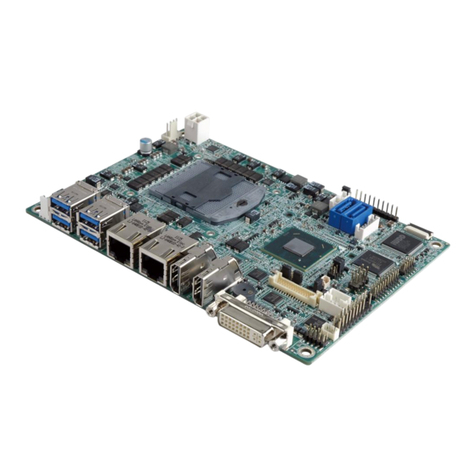
Aewin AW-EM751 Series User manual

Intel Pemtium M- 5.25” Embedded Single Board Computer
With VGA/LCD, LAN, AUDIO, TV-OUT, DVI Interface
User’s Manual
Version 1.1

User’s manual 1
AW-EM751
© Copyright 2002. All Rights Reserved
Manual edition 1.0, Jan. 2002
This document contains proprietary information protected by copyright. All
rights are reserved, no part of this manual may be reproduced, copied, translated
or transmitted in any form or by any means without prior written permission of the
manufacturer.
The content of this manual is intended to be accurate and reliable, the original
manufacturer assumes no responsibility for any inaccuracies that may be
contained in this manual. The original manufacturer reserves the right to make
improvements to the products described in this manual at any time without prior
notice.
Trademarks
IBM, EGA, VGA, XT/AT, OS/2 and PS/2 are registered trademarks of International
Business Machine Corporation
Intel and Pentium M are registered trademarks of Intel Corporation
Award is a trademark of Award Software International, Inc
RTL is a trademark of Realtek Semi-Conductor Co., Ltd
ADI is a trademark of Analog Device Inc.
Winbond is a trademark of Winbond Technology, Inc
CF and CompactFlash are trademark of SanDisk Corporation
Microsoft, Windows, Windows NT and MS-DOS are either trademarks or
registered trademarks of Microsoft Corporation
All other product names mentioned herein are used for identification purpose only
and may be trademarks and/or registered trademarks of their respective
companies
Limitation of Liability
While reasonable efforts have been made to ensure the accuracy of this manual,
the manufacturer and distributor assume no liability resulting from errors or
omissions in this manual, or from the use of the information contained herein.

User’s manual
2
AW-EM751
Table of Contents
Chapter 1. General information……………………………………….4
1.1
Introduction-----------------------------------------------------------------4
1.2 Specification---------------------------------------------------------------------------------4
1.3 Board Layout……………………………………………………………………..6
1.5 Board Dimension---------------------------------------------------------------------------6
Chapter 2. Connectors/Jumpers Location and Define ………….8
2.1 Connectors/Jumpers Location and Define---------------------------------------------8
2.2 Jumpers Location and Define -------------------- ---------------------------------------9
2.3 Connectors Pin Define --------------------------------------------------------------------10
CN1:CPU FAN Connector --------------------------------------------------------------------10
CN2:TV-Out Connector-----------------------------------------------------------------------11
CN3:DVI Connector----------------------------------------------------------------------------11
CN4:VGA Connector---------------------------------------------------------------------------12
CN5:LVDS Channel 1 Connector ------------------------------------------------------------12
CN6:LVDS Channel 2 Connector ---------------------------------------------------------12
CN7:LVDS Panel Backling Enable Control Connector ---------------------------------13
CN8:System FAN 2 Connector ------------------------- --------------------------------------13
CN9:USB Port 3/4 Connector --------------------------------------------------------------14
CN11:USB 1/2 Connector ----------------------------------------------------------------------14
CN12:IDE Power Connector ----------------------------------------------------------------15
CN13:IRDA Power Connector --------------------------------------------------------------15
CN14:DC-IN Power Connector ---------------------------------------------------------------15
CN15:System FAN 1 Connector ---------------------------------------------------------------16
CN17:Audio Input/Output Connector -------------------------------------------------------16
CN16:IDE Connector ----------------------------------------------------------------------------16
CN18:Floppy Drive Connector ----------------------------------------------------------------17
CN20:Parallel Port Connector -----------------------------------------------------------------18
CN19:Aux-In Connector ------------------------------------------------------------------------19
CN21:CD Analog –In Connector --------------------------------------------------------------20
CN22:COM Port 1-4 Connector ---------------------------------------------------------------20
CN23:LAN Connector ---------------------------------------------------------------------------22
CN24:PS/2 Keyboard/mouse Connector -----------------------------------------------------23
CN25:Front Panel Connector ------------------------------------------------------------------23
CN26:GPIO Port Connector -----------------------------------------------------------------24

User’s manual 3
AW-EM751
2.4 Jumper Setting ----------------------------------------------------------------------------24
JP1:TV Video Output Format Selection -------------------------------------------------24
JP3:Clear CMOS------------------------------------------------------------------------------24
JP4:LVDS Panel Power Selection ………………………………………………… 25
JP5:FSB Clock Selection ……………………………………………………………25
JP6:COM4/4 RI Pin Function Selection(RI/+5V/+12V) ………………………….25
JP7/JP8/JP9:COM2 RS232/422/486 Model Selection ……………………………26
Chapter 3. BIOS SETUP--------------------------------------------------------------------29
3.1 Quick Setup--------------------------------------------------------------------------------29
3.2 Entering the CMOS Setup Program-------------------------------------------------29
3.3 Menu Options-----------------------------------------------------------------------------31
Standard CMOS Features-------------------------------------------------------------------32
Advanced BIOS Features-------------------------------------------------------------------34
Advanced Chipset Features-----------------------------------------------------------------35
Integrated Peripherals-----------------------------------------------------------------------36
IR Transmission Delay…………………………………………………………. …40
Power Management Setup-------------------------------------------------------------------40
PNP/PCI Configuration----------------------------------------------------------------------43
PC Health Status-------------------------------------------------------------------------------44
Load Fail-Safe Default------------------------------------------------------------------------45
Load Optimized Default----------------------------------------------------------------------40
Chapter 4. Drivers and Utilities -------------------------------------------------------------49
4.1 System Driver Installation ---------------------------------------------------------------49
4.2 Video Driver Installation------------------------------------------------------------------51
4.3 LAN Driver Installation ..………………………………………………………..53
4.4 Audio Driver Installation…………………………………………………………57
4.5Appendix A. System Resources------------------------------------------------------------59
4.6Appendix B. Cable List---------------------------------------------------------------------62
4.7Appendix C. Optional Peripherals ………………………………………………63

User’s manual
4
AW-EM751
Chapter 1. General Information
1.1 Introduction
The AW-EM751 is a 5.25” embedded single board use Intel 82855GM(E)
and ICH4 chipset supports Intel® Pentium M™ processors with 400/(533)MHz
system bus in 478-pin micro-FCPGA package. The AW-EM751 supports Intel®
82562EX/EZ for 10/100Mbps Fast Ethernet speed.
The onboard features include three RS-232 and one RS-232/422/485 serial ports,
one bi-directional parallel port, four USB ports.Also the AW-EM751
Supports AC-97 audio interface,CardBus interface with two PCMCIA card
slots,one CompactFlash™ socket ,TV-out,DVI and LVDS LCD interface.
1.2 Specification
Specifications
General Functions
CPU Intel® Pentium M Processor in 478-pin micro-FCPGApackage.
BIOS Award® 512KB Flash BIOS.
Cache CPU On-die,1-Mbyte second level cache.
Chipset Intel® 855GM(E)+ICH4
I/O Chipset Dual Winbond W83627HF-AW
Memory
Two 184-pin DDR DIMM sockets support DDR200/266/(333)
DDR devices and up to 2G bytes.
ECC Support.
Enhanced IDE Support up to two IDE devices (Ultra DMA 33/66/100)
FDD interface Supports one 34-pin header up to two floppy disk drives.
Parallel port Support SPP/ECP/EPP
Serial port Three RS-232 and one RS-232/422/485 serial ports.
IR interface Support one IrDATx/Rx header
KB/Mouse connector Support PC/AT keyboard and PS/2 mouse
USB connectors four USB ports support USB 1.1 and 2.0
Battery Lithium battery for data retention up to 10 years(in normal
condition)

User’s manual 5
AW-EM751
Watchdog Timer Support software selectable timeout interval
System Monitoring Built in W83627HF-AW; supports temperatures, Fan speed, and
voltages monitoring
PCI slot One 32-bit PCI expansion slot support two bus mater.
Digital I/O Support four TTL input and four output pins for customized purpose
Power management Support ACPI 2.0, Wake on LAN and Modem Ring-in functions
Flat Panel/CRT Interface
Chipset Built in Intel® GMCH(855GM\GME)
Display memory
Display type Support CRT display,single or dual channel LVDS panel.
Resolution
350-MHz integrated 24-bit RAMDAC that can drive a standard
progressive scan analog monitor with pixel resolution up to 1600
x1200 at 85Hz and up to 2048x1536 at 75Hz.
TV-Out Interface
Chipset Chrontel digital TV encoder
TV Format Support NTSC and PAL signals format
Ethernet interface
Chipset Intel® 82562EZ/EX for 100/10 Base-Tx Fast Ethernet controller
Sound Interface
Chipset AC97 codec ( Realtek ALC650 )
Audio Interface Mic in , Line in , Speaker out , CD audio in and AUX in
CardBus Interface
Chipset TI PCI 1420 CardBus controller
Interface
Complies with PCMCIA v.2.10 and JEIDA v.4.1 provide full supprts
for all type I/II/III
PCMCIA memory,I/O and ATA hard disk card.
SSD Interface
One 50-pin CompactFlash™ socket
Mechanical and Environmental
Power supply voltage 13V ~ 25V

User’s manual
6
AW-EM751
Max. power requirements 3.9A@18V
Operating Temperature 32-140ºF (0-60℃)
Board size 8"(L) x 5.75"(W)(203mm x 146mm)
1.3Board Layout
1.4 Board Dimension
Top Side

User’s manual 7
AW-EM751
Bottom Side

User’s manual
8
AW-EM751
Chapter 2. Connectors/Jumpers Location and Define
2.1 Connectors/Jumpers Location and Define
Top Side-
Connector Define Connectors Define
CN1 CPU FAN Connector CN14 DC Power Connector
CN2 TV-Out Connector CN15 System Fan1 Connector
CN3 DVI Connector CN16 IDE Connector
CN4 CRT Connector CN17 Audio In/Out Connector
CN5 LVDS CH1 Connector CN18 Floppy Drive Connector
CN6 LVDS CH2 Connector CN19 Aux-In Connector
CN7 LVDS Panel Backligt
Enable Connector
CN20 Parallel Port Connector
CN8 System FAN2 Connector CN21 CD Analog-In Connector
CN9 USB Port 2 Connector CN22 COM Port 1-4 Connector
CN10 CardBus Connector CN23 LAN Connector
CN11 USB Port 1 Connector CN24 KB/MS Connector

User’s manual 9
AW-EM751
CN12 IDE Power Connector CN25 Front Panel Connector
CN13 IRDA Connector CN26 GPIO Ports Connector
Bottom Side-
Connector Define Connectors Define
CN27 Compact Flash Socket
2.2 Jumpers Location and Define

User’s manual
10
AW-EM751
Label Define
JP1 TV Video Output Format Selection ( NTSC/PAL)
JP3 Clear CMOS
JP4 LVDS Panel Power Selection
JP5 System Bus Clock Selection
JP6 COM3/4 RI/+5V/+12V Selection
JP7 COM2 RS232/422/485 Mode Selection-1
JP8 COM2 RS232/422/485 Mode Selection-2
JP9 COM2 RS232/422/485 Mode Selection-3
2.3 Connectors Pin define
CN1: CPU FAN Connector

User’s manual 11
AW-EM751
Pin Define
1 Ground
2 +12V
3 Speed Detect
CN2: TV-Out Connector
Pin Define
1 LUMINANCE OUT
2 CROMIANCE OUT
3 Ground
4 Ground
5 COMPOSITE OUT
CN3: DVI Connector
Pin Define Pin Define
1 Ground 2 Ground
3 TX2N 4 TX0N
5 TX2P 6 TX0P
7 Ground 8 Ground
9 CLK 10 TXCN
11 DATA 12 TXCP
13 Ground 14 Ground
15 TX1N 16 CHARGE
17 TX1P 18 +5V
19 Ground 20 +5V

User’s manual
12
AW-EM751
CN4: VGA Connector
Pin Define Pin Define
1 Red 2 Green
3 Blue 4 NC
5 Signal Ground 6 Chassis Ground
7 Chassis Ground 8 Chassis Ground
9 NC 10 Signal Ground
11 NC 12 DDC Data
13 H-SYNC 14 V-SYNC
15 DDC Clock 16 NC
CN5: LVDS Channel 1 Connector
Pin Define Pin Define
1 VCC 2 VCC
3 Ground 4 Ground
5 RXO0-/RXIN0- 6 RXO0+/RXIN0+
7 Ground 8 RXO1-/RXIN1-
9 RXO1+/RXIN1+ 10 Ground
11 RXO2-/RXIN2- 12 RXO2+/RXIN2+
13 Ground 14 RXOC-/RXCLKIN-
15 RXOC+/RXCLKIN+ 16 Ground
17 RXO3- 18 RXO3+
19 LVDS-DDC-DATA 20 LVDS-DDC-CLK
CN6: LVDS Channel 2 Connector

User’s manual 13
AW-EM751
Pin Define Pin Define
1 RXE0- 2 RXE0+
3 Ground 4 RXE1-
5 RXE1+ 6 Ground
7 RXE2- 8 RXE2+
9 RXEC- 10 RXEC+
11 RXE3- 12 RXE3+
13 Ground 14 Ground
15 NC 16 Ground
17 VCC 18 VCC
19 VCC 20 VCC
CN7: LVDS Panel Backlight Enable Control Connector
Pin Define
1 +12V
2 Ground
3 Ground
4 +5V
5 SMBUS Clock
6 N.C
7 Backlight Enable
CN8: System FAN2 Connector

User’s manual
14
AW-EM751
Pin Define
1 Ground
2 +12V
3 Fan Speed Detect
CN9: USB Port 3/4 Connector
Pin Define Pin Define
1 USB VCC 2 USB VCC
3 USB D3- 4 USB D4-
5 USB D3+ 6 USB D4+
7 Ground 8 Ground
9 NC 10 Ground
CN11: USB1/2 Connector
Pin Define Pin Define
1 USB VCC 2 USB VCC
3 USB D1- 4 USB D2-
5 USB D1+ 6 USB D2+
7 Ground 8 Ground
9 NC 10 Ground

User’s manual 15
AW-EM751
CN12: IDE Power Connector
Pin Define
1 +12V
2 Ground
3 Ground
4 +5V
CN13: IRDA Power Connector
Pin Define
1 +5V
2 NC
3 IRRX
4 Ground
5 IRTX
CN14: DC-IN Power Connector

User’s manual
16
AW-EM751
Pin Define
1 +DC Input (12~25V)
2 Ground
CN15: System FAN1 Connector
Pin Define
1 Ground
2 +12V
3 Fan Speed Detect
CN17: Audio Input/Output Connector
Pin Define Pin Define
1 Line-In(R)/Surround(R) 2 NC
3 Ground 4 Line-In(L)/Surround(L)
5 NC 6 NC
7 NC/LFE-OUT 8 NC
9 Ground 10 MIC-In/Cent-Out
11 Speaker-Out(R) 12 NC
13 Ground 14 Speaker-Out(L)
CN16: IDE Connector

User’s manual 17
AW-EM751
Pin Define Pin Define
1 RESET* 2 Ground
3 DATA7 4 DATA8
5 DATA6 6 DATA9
7 DATA5 8 DATA10
9 DATA4 10 DATA11
11 DATA3 12 DATA12
13 DATA2 14 DATA13
15 DATA1 16 DATA14
17 DATA0 18 DATA15
19 Ground 20 KEY PIN
21 DREQ 22 Ground
23 DIOW* 24 Ground
25 DIOR* 26 Ground
27 IOCHRDY 28 CSEL
29 DACK* 30 Ground
31 IRQ14 32 N/C
33 A1 34 DETECT
35 A0 36 A2
37 HD SELECT 0* 38 HD SELECT 1*
39 ACTIVE* 40 Ground
CN18: Floppy Drive Connector

User’s manual
18
AW-EM751
Pin Define Pin Define
1 Ground 2 DENSITY SELECT0*
3 Ground 4 NC
5 Ground 6 DENSITY SELECT1*
7 Ground 8 INDEX*
9 Ground 10 MOTOR ENABLE 0*
11 Ground 12 DRIVE SELECT 1*
13 Ground 14 DRIVE SELECT 0*
15 Ground 16 MOTOR ENABLE 1*
17 Ground 18 DIRECTION*
19 Ground 20 STEP*
21 Ground 22 WRITE DATA*
23 Ground 24 WRITE GATE*
25 Ground 26 TRAK00*
27 Ground 28 WRITE PROTECT*
29 Ground 30 READ DATA*
31 Ground 32 SIDE 1 SELECT*
33 Ground 34 DISK CHANGG*
CN20: Parallel Port Connector

User’s manual 19
AW-EM751
Pin Define Pin Define
1 STROBE 14 AFD#
2 PD0 15 ERR#
3 PD1 16 INIT#
4 PD2 17 SLIN#
5 PD3 18 Ground
6 PD4 19 Ground
7 PD5 20 Ground
8 PD6 21 Ground
9 PD7 22 Ground
10 ACK# 23 Ground
11 BUSY 24 Ground
12 PE 25 Ground
13 SLCT 26 NC
CN19: Aux-In Connector
This manual suits for next models
2
Table of contents
Other Aewin Single Board Computer manuals
Popular Single Board Computer manuals by other brands
Lanner electronics
Lanner electronics IAC-H670 Series user manual

Fortec Star
Fortec Star iBASE IB918 manual

AtGames
AtGames LEGENDS CONNECT instruction manual
IEI Technology
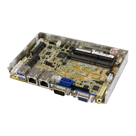
IEI Technology WAFER-ULT-i1 user manual
Digi
Digi ConnectCore MP13 Hardware reference manual
AXIOMTEK
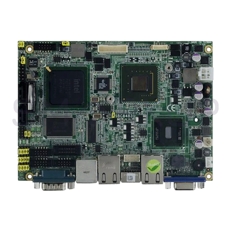
AXIOMTEK SBC84831 Series user manual
