AFi ISA AFI-CI060V Series User manual

Maintenance Manual -
Revision 1.1 - English version

602697
This document has been prepared with the utmost care. However, AFI
Centrifuge refuses to accept any responsibility in the event of errors or
omissions. The same applies to any damage arising from the use of
information contained in this manual.
AFI Centrifuge
3, Rue Nicolas Copernic
ZA Nord Bazouges
53200 CHATEAU-GONTIER
FRANCE
+33 (0) 2 43 06 66 76
Original Instructions - Rev.1.0 Service Manual– ISA Centrifuges 2/ 27
You have just purchased one of the finest Laboratory Centrifuges available. With proper care, maintenance
and laboratory procedure, this centrifuge will provide you years of productive service. Please read this manual
carefully to familiarize you with proper installation, and operation of the centrifuge. ther information are
available on our website,
www.aficentrifuge.com
.
Warranty
AFI Centrifuge warrants ISA Centrifuges that it will repair F. .B. its factory or furnish without charge F. .B. its
factory a similar part to replace any material in its equipment within 24 months after the date of sale if proved
to the satisfaction of the company to have been defective at the time it was sold provided that all parts claimed
defective shall be returned, properly identified to the company at its factory, charges prepaid. Factory installed
equipment or accessories are warranted only to the extent guaranteed by the original manufacturer, and this
warranty shall not apply to any portion of the equipment modified by the user. Claims under this warranty
should be directed to AFI Centrifuge. Setting forth in detail the nature of the defect, the date of the initial
installation and the serial and model number of the equipment.
This warranty shall not apply to any AFI Centrifuge product or part thereof which has been subject to misuse,
abuse, accident, shipping damage, improper installation or service, or damage by fire, or flood. If the serial
number of this product is altered, removed or defaced as to be illegible, the Warranty shall be null and void in
its entirety.
The warranty is for the sole benefit of the original purchaser and is not assignable or transferable. Prior to
returning any item, for any reason, contact AFI Centrifuge for a Return Authorization Number. This number must
accompany all returns. Any product shipped to AFI Centrifuge without this number will be returned refused
shipment or collect freight.
Explanation of Symbols
Safety alert symbol indicates a potentially hazardous
situation which, if not avoided, could result in death or
serious injury
CAUTI N used without the safety alert symbol indicates
a potentially hazardous situation which, if not avoided,
may result in property damage.
Safety alert symbol indicates a potentially hazardous
situation which, if not avoided, may result in minor or
moderate injury.
Pinching: This warning symbol indicates the presence of
a risk of pinching when handling the lid.
Note: Used for important information
Potential electrical hazard, only qualified person to
access
Biohazard
Ground, Earth
Lead Free
CAUTION
CAUTION
WARNING

Original Instructions - Rev.1.0 Service Manual– ISA Centrifuges 3/ 27
Table of contents
1
DESCRIPTION OF THE CENTRIF GE .......................................................................................................... 5
1.1
E
LECTR NIC
C
NTR L
C
ENTER
/
B
L CK
................................................................................................................... 5
1.2
L
CK
................................................................................................................................................................. 7
1.3
M
T R
............................................................................................................................................................. 9
1.4
S
PEED SENS R
..................................................................................................................................................... 9
1.5
T
EMPERATURE PR BE
........................................................................................................................................... 9
1.6
I
MBALANCE SENS R
.............................................................................................................................................. 9
1.7
G
AS SPRING
........................................................................................................................................................ 9
1.8
A
BS RPTI N F VIBRATI NS
................................................................................................................................ 10
1.9
R
EFRIGERATI N
S
YSTEM
...................................................................................................................................... 10
2
TRO BLESHOOTING & MESSAGES ..........................................................................................................11
2.1
T
R UBLESH TING
............................................................................................................................................ 11
2.2
R
EMINDER MESSAGES
......................................................................................................................................... 13
3
SETTINGS ................................................................................................................................................14
3.1
A
CCESS T PARAMETERS
...................................................................................................................................... 14
3.2
U
NBALANCING
S
ENSITIVITY
S
ETTING
...................................................................................................................... 18
3.3
S
ETTING THE
T
IME
D
ELAY F THE L CK
................................................................................................................... 19
3.4
L
ADING THE FIRMWARE
..................................................................................................................................... 19
4
STANDARD EXCHANGE OF COMPONENTS ..............................................................................................19
4.1
S
AFETY
R
ULES
................................................................................................................................................... 19
4.2
T
ERMIN L GY
.................................................................................................................................................. 19
4.3
S
PARE PARTS
&
T LS
........................................................................................................................................ 20
4.4
S
ETTING F RM
.................................................................................................................................................. 21
5
F NCTIONAL CHECKS ..............................................................................................................................22
5.1
S
AFETY
............................................................................................................................................................. 22
5.2
S
PEED
C
HECK
.................................................................................................................................................... 23
5.3
C
HECKING THE
T
IMER
......................................................................................................................................... 23
5.4
C
HECKING THE
T
EMPERATURE
(R
EFRIGERATED M DEL
) ............................................................................................. 23
6
ELECTRICAL DIAGRAMS...........................................................................................................................24
6.1
0.6
L
ITER
V
ENTILATED
M
DEL
:
ISA
/
AFI-CI060V
&
AFI-CI060V-E
SERIES
............................................................... 24
6.2
0.6
L
ITER
R
EFRIGERATING
M
DEL
:
ISA
/
AFI-CI060R
&
AFI-CI060R-E
SERIES
.......................................................... 25
7
REFRIGERATING SYSTEM ........................................................................................................................26
7.1
0.6
L
ITER
120V
/
230V
M
DEL
/
ISA
–
AFI-CI060R-E .......................................................................................... 26
8
ANNEXES ................................................................................................................................................27
8.1
R
ETURN AUTH RIZATI N
..................................................................................................................................... 27
8.2
S
FTWARE UPDATE
.............................................................................................................................................. 1

Original Instructions - Rev.1.0 Service Manual– ISA Centrifuges 4/ 27
Updates
Date Revision Modification Paragraph Author
2019 August 27
th
2020 Jun 6th
1.0
1.1
Creation
Modification – Temperature Check
All
5.4
LS / FB
FB

Original Instructions - Rev.1.0 Service Manual– ISA Centrifuges 5/ 27
1Description of the Centrifuge
The centrifuge range is composed of:
References Model
AFI-CI060V Ventilated, 120V / 60Hz
AFI-CI060V-E Ventilated, 230V / 50-60Hz
AFI- CI060R Refrigerating, 120V / 60Hz
AFI- CI060R-E Refrigerating, 230V / 50Hz
The centrifuge is composed of:
•an electrical block, called Ogival Control Center
•a lock
•a motor
•a ventilation or refrigeration system (depending on the model)
•a lid
It is equipped with one or several rotors:
•Free or swing-out
•Angular
The free rotors are fitted with:
•Buckets
•Tube adapters or inserts
•Watertight lids
Some angular rotors are equipped with tight fitting lids.
1.1 Electronic Control Center / Block
Electronic control center is included in an ogival block.
It includes touch buttons, a knob, a lid opening button, as well as the microcontroller electronic board,
It is also equipped with RGB LED lighting for various color lighting.
There is no provision for changing the elements composing the Control. It is a complete separate part. In case of
defective element, a standard exchange of the complete Control Center must be considered, which facilitates the
restoration of the centrifuge.
The power electronic board is located inside the centrifuge body, on a power electronic “rack”. This can be ordered
independently for replacement.
Start/Stop Button
There is no main electrical switch on ISA centrifuges.
When connected to power supply through the power cord, the centrifuges turns ON.
To switch to stand-by mode, press & hold START/STOP button.
Logo Short press Press & hold
ISA series

Original Instructions - Rev.1.0 Service Manual– ISA Centrifuges 6/ 27
Validation Button
validation button is the following one ,
Logo Short press Press & hold
ISA series
Setting controls
Values can be directly adjusted using the front panel Knob
Logo
ISA series
Lid Opening Button
The lid opening is controlled by the button on the right side of the Control Center.
Electronic microcontroller Board
The electronic microcontroller board is located under the display card. The data for controlling the various parts
are stored in this board, in the form of firmware.
The connection for the update of this firmware, via USB key, is described in 3.4 Loading the firmware
Original Instructions - Rev.1.0 Service Manual– ISA Centrifuges 7/ 27
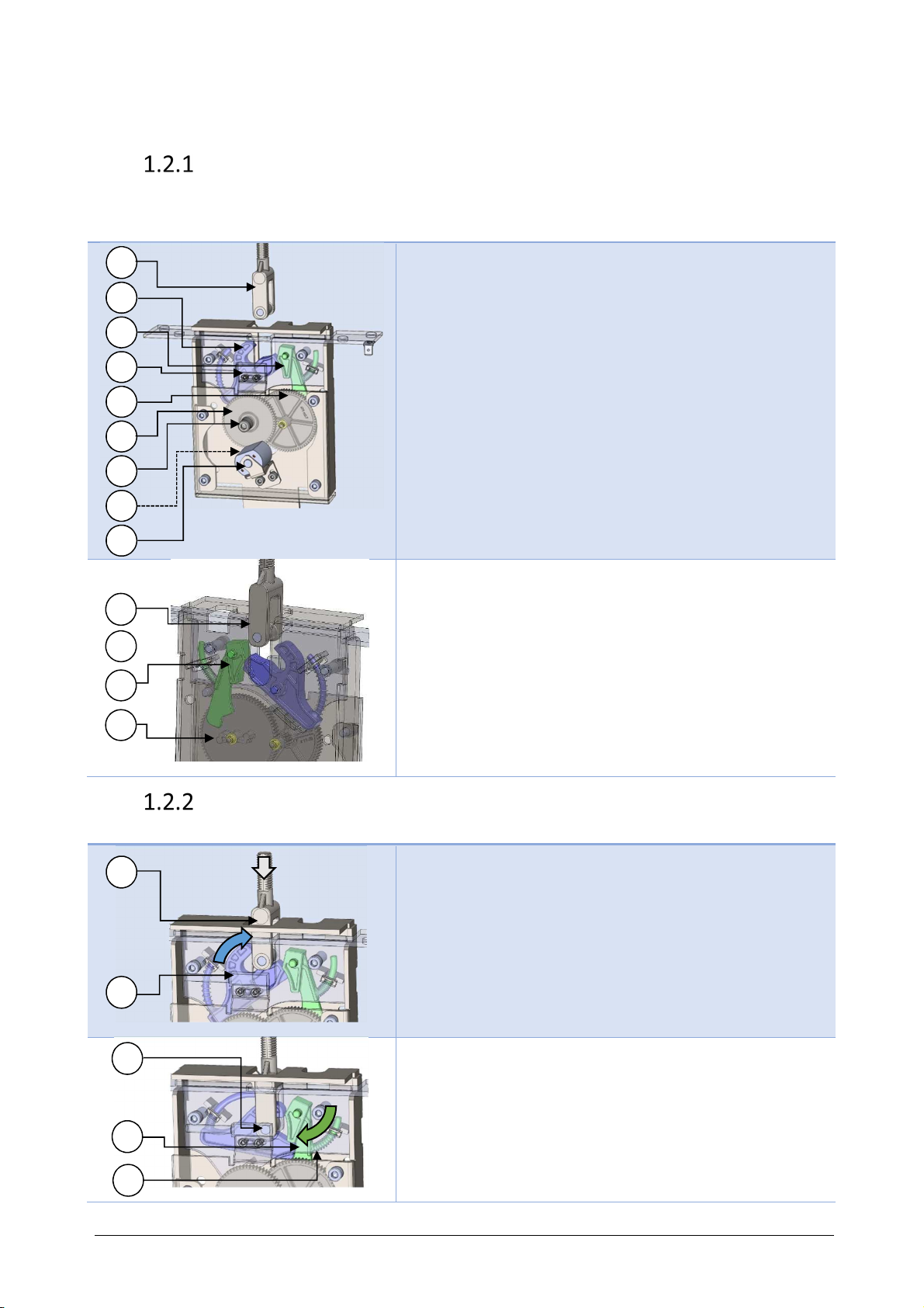
1.2 Lock
Description
ISA / AFI-CI060 series are equipped with an electric lid opening. Lid closing is a manual operation
Visual Description
Fig. 1 Lock front view
(1) Lid latch, permanent magnet equipped.
(2) Hook.
(3) Pendulum.
(4) Microswitch contact (ILS sensor).
(5) Cogwheel (3x) :
(5a) Ratchet cogwheel
(5b) Intermediate cogwheel
(5c) Drive hole
(5d) Motor cogwheel (not visible here)
(6) Motor.
Fig. 2 Lock back view
(1) Lid latch.
(2) Hook.
(3) Pendulum.
(5a) Ratchet cogwheel
Locking the lid
Visual Description
Fig. 3 Lock back view –locking kinematics start
1. The lid is manually lowered.
2. When lowered, the lid latch (1) pushes down the hook (2).
The hook (2) toggles to lock position
Fig. 4 Lock back view – Locked position
3. The pendulum (3) rotates, activated by a spring (3a).
It maintains the hook in locked position.
4. The permanent magnet (1a) on the latch switches on the
ILS sensor. The locked position is now electrically
detected.
2
1
3
5a
6
5d
1
2
3
3a
1a
4
2
1
3
5b
5c
5a

Original Instructions - Rev.1.0 Service Manual– ISA Centrifuges 8/ 27
nlocking the lid
Visual Description
Fig. 5 Lock back view – Locked position
1. The lid is locked :
The pendulum (3) maintains the hook (2) in its position.
Fig. 6 Ratchet cogwheel pushing pendulum
2. When activated, the ratchet cogwheel (5a) pushes the
pendulum (3).
Fig. 7 Pendulum pushed
3. Pendulum (3) is completely pushed.
4. The hook (2) is now free to toggle.
Fig. 8 Rotation of the hook
5. The hook (2) toggles, activated by spring force
6. The lid latch (1) is now released.
Fig. 9 Released lid latch
7. The lid rises, helped by gas
2
3
2
3
3
5a
1
3

Original Instructions - Rev.1.0 Service Manual– ISA Centrifuges 9/ 27
1.3 Motor
Three phases induction motor powered in variable voltage & frequency.
It has an integrated over temperature sensor. It measures the heating of the internal motor winding, and sends a
signal from 130 degrees Celsius. Centrifuge then display error code “# 04”.
1.4 Speed sensor
The speed sensor is a Hall Effect magnetic sensor, placed under the motor. Six (6) magnets with alternating poles
are placed on a rotating disc. The sensor measures the frequency of passage of the magnets, to determine the speed.
1.5 Temperature probe
It is located in the bowl gasket, and therefore in the rotor airflow when the rotor is in rotation.
The measurements are only taken when the rotor is rotating.
sensor is a PT500 class A probe.
At the beginning of a cycle the displayed temperature is the air temperature (air around the sensor), once target
temperature reached, the displayed temperature is that of the samples.
Before being centrifuged, the sample must be brought to the program setpoint temperature.
Use either an oven, or a refrigerator to bring it to the desired temperature.
The centrifuge is designed to maintain the temperature during a rotation cycle.
1.6 Imbalance sensor
In the case of a load presenting an imbalance, the oscillations caused will be higher than the centrifuge’s own
vibration.
The vibration sensor then intervenes to detect the movements of the centrifuge. This sensor is an electronic
accelerometer.
The systematic minimum threshold detection is: 9 gr. The detection results in an immediate shutdown of the power
supply to the motor, and a slowdown of the rotor free wheel.
This threshold is adjustable according to the media on which the centrifuge rests, in order for the imbalance sensor
to always be triggered with a minimum imbalance of 9 gr.
Cf. § 3.2Unbalancing Sensitivity Setting for the procedure to adjust the imbalance detection threshold.
1.7 Gas spring
A single cylinder allows the opening of the lid when it is released by the lock. It is a gas cylinder, fitted with a
spring. This spring allows a better relaxation at the opening start. The cylinder should open the lid without causing
rebound of the latter at the end of travel.

Original Instructions - Rev.1.0 Service Manual– ISA Centrifuges 10/ 27
1.8 Absorption of vibrations
Any system has its own resonance frequency, which will cause oscillations. The dissipative elements of these
oscillations, which translate into vibrations, are anti-vibration mounts, numbering 3. This set will allow for
absorbing parasitic movements whatever the rotor, its load, and its speed, providing that the load is balanced.
Those 3 shock absorbers are placed vertically between the motor and the stabilizer bed.
1.9 Refrigeration System
The refrigerating model allows the maintenance of a sample at its initial temperature, while undergoing a rotation.
Take care to let free space around the centrifuge for airflow renewing.

Original Instructions - Rev.1.0 Service Manual– ISA Centrifuges 11/ 27
2Troubleshooting & Messages
2.1 Troubleshooting
Error Codes / Description Cause Solution
01
Reserved Not used code
02
IMBALANCE Buckets don't swing freely. Clean the rotor trunions and corresponding
areas on buckets. Apply a thin film of supplied
grease on these locations. Cf. § Erreur !
Source du renvoi introuvable. Erreur !
Source du renvoi introuvable..
The rotor buckets are not loaded
symmetrically. Wait until complete stop.
Open the lid.
Load the buckets as shown in manual.
Start a new cycle.
The centrifuge is installed on an
uneven bench. Install the centrifuge on a flat bench/table, as
described in manual.
The imbalance detector is not well
calibrated. Contact a Certified Technician.
03 BOWL
OVERTEMPERATURE The temperature in the bowl is
higher than 50 °C; the room
temperature is too high.
Wait until complete stop.
Turn the AC or Ventilation system on to
obtain an ideal ambient temperature as
described in manual.
The temperature set in the program
is not adapted. The settings for speed / temperature are not
compatible with a normal utilization.
The temperature of the samples is
too high. Make sure the samples can be cooled to down
to a temperature between 4 °C and 37 °C
during 1 hour before being introduced in the
centrifuge
The refrigeration doesn’t work. Contact a Certified Technician.
The temperature probe is
malfunctioning. Contact a Certified Technician.
04 MOTOR
OVERTEMPERATURE The motor temperature is too high. A « no-brakes / free wheel» stop is occurring.
Wait complete stop before opening the lid.
Turn the AC or Ventilation system on to
obtain an ideal ambient temperature as
described in manual.
The centrifuge is being used too
intensively (ventilated model). Let the centrifuge cool down between cycles.
The motor has been damaged Contact a Certified Technician.
The temperature sensor on the
motor has a bad connection. Contact a Certified Technician.
05 LID REED SENSOR
NOT RELEASED -
OPEN
The “Reed” contact doesn’t work.
The connection of the micro
contact is not good.
The locking device is
mechanically blocked.
The “Reed” sensor was seen as closed when it
should have been seen as open (released)
when the lid opened.
Contact a Certified Technician.
06
Reserved
07
Reserved
08 POWER BOARD
SECURITY DEFAULT The power board is working
improperly. Contact a Certified Technician.
The connection to this board parts
is not good. Contact a Certified Technician to check (P1,
P3, P4, P5 pins).
09 NO SPEED SIGNAL
AT START No speed measurement within 20s
after the start of the centrifuge
The speed sensor is defective.
The speed sensor or the connection of these
elements is defective
Contact an authorized technician.

Original Instructions - Rev.1.0 Service Manual– ISA Centrifuges 12/ 27
Motor is diconnected / not
properly connected
The power board is not able to
feed the motor
Contact an authorized technician.
Contact an authorized technician
10 SPEED SIGNAL LOST The speed sensor is working
improperly.
The power board is working
improperly.
The connection to these parts is
not good.
The speed signal was lost more than 6s during
rotation.
Wait for the end of the displayed countdown
before opening the centrifuge. call a Certified
Technician
11 Reserved
12 OVERSPEED Major error, the centrifuge will
stop.
Speed control device is working
improperly.
The speed measured is higher than the
maximum speed allowed for this rotor.
Check the rotor is compatible with set speed.
Contact a Certified Technician.
13 Reserved
14 Reserved
15 LID OPEN DURING
ROTATION Manual lid opening during
centrifugation, with the supplied
opening key.
Wait for the rotor stop without trying to brake
it manually: Danger: Risk of injury.
Press the START / STOP key: The message
disappears.
Press the lid control button: The mechanism
initializes.
Wrong adjustment of locking
mechanism. The hook was slightly released during the
centrifugation (enough to release the Lid lock
“Reed” sensor).
Contact a Certified Technician.
16 TEMPERATURE
CONTROL ISSUE Temperature probe out of service. Verify that the temperature probe is properly
installed under the lid and replace it if
necessary.
Remove the probe and measure the resistance.
The value must be 500+ - 100 Ohm (Probe
PT500)
17 Reserved
/ NO DISPLAY No power.
Centrifuge entered “IDLE” mode
after 4h of inactivity. In this case a
short blue flash can be observed
(Knob backlight)
Verify the power plug is connected properly.
Check the power in the laboratory.
Turn the switch on.
A short press on any key allow to wke the
system up.

Original Instructions - Rev.1.0 Service Manual– ISA Centrifuges 13/ 27
2.2 Reminder messages
According machine status, recall message are displayed.They are composed of a message number & a logo.
Message
# Logo Cause Solution Command
01
The rotor needs to be greased after
200 cycles runs. Dispense synthetic grease
following Erreur ! Source du
renvoi introuvable. Erreur !
Source du renvoi introuvable.,
To acknowledge the message,
press START/STOP.
02
When less than 2,000 cycles remain
before end of rotor life, this
message appears each time a cycle
is started. The number of cycles
remaining before the machine is
stopped is displayed.
Provide rotor replacement and
complete control of the machine
before putting it back into service.
03
The rotor and its buckets have
reached the end of their life. They
are obsolete. The centrifuge and its
rotor are no longer usable until the
rotating accessory has been
changed.
Contact a dealer to renew your
rotating accessories. An
authorized technician will
proceed with the return to service.
Original Instructions - Rev.1.0 Service Manual– ISA Centrifuges 14/ 27
3Settings
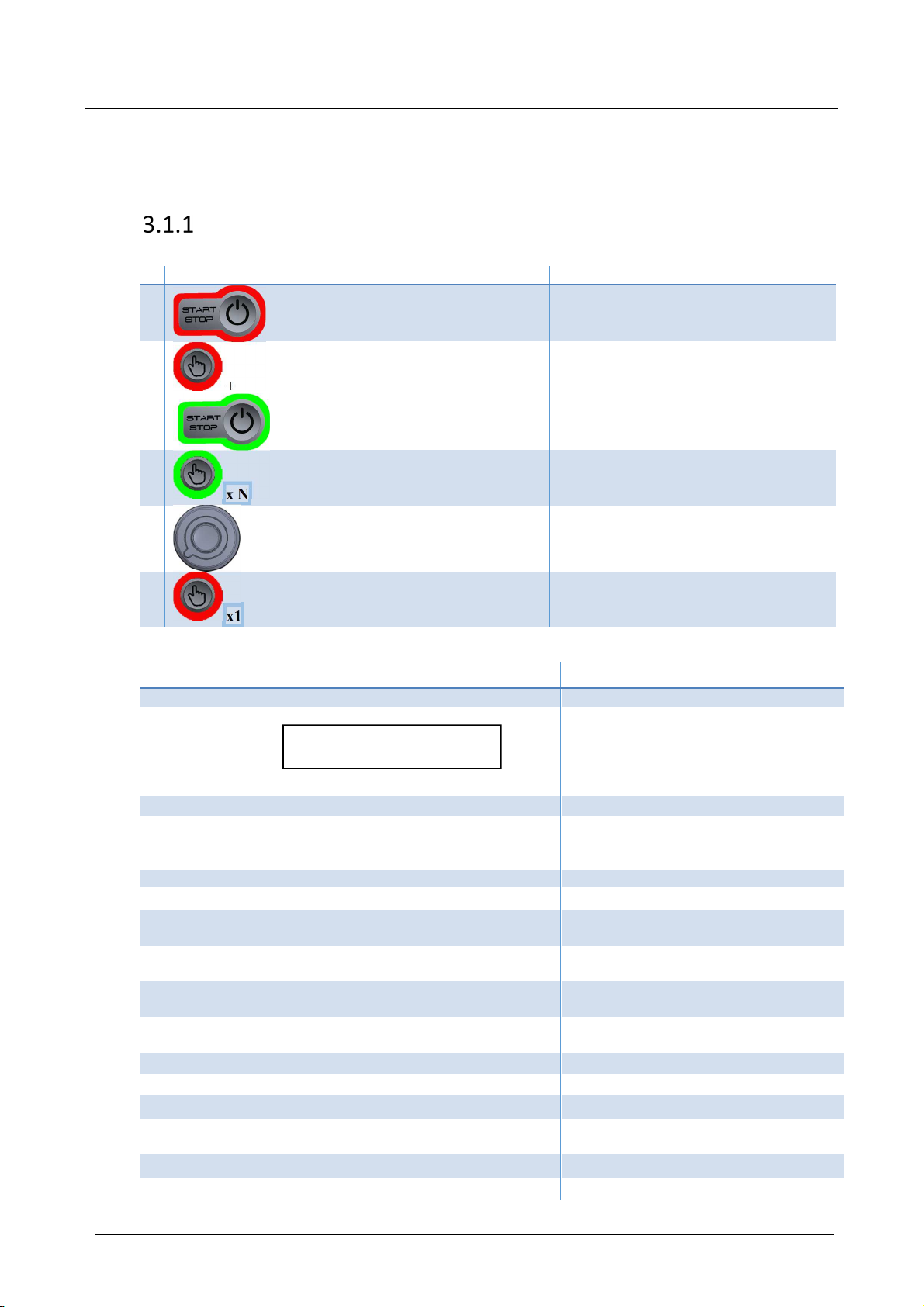
3.1 Access to parameters
Advanced parameters
To access to advanced parameters menu, follow instructions:
# Action on ISA
Instruction
Effect
1
Press & hold START/STOP button to
switch to sleep mode.
2
+
Press & hold validation button & press
START button to access to advanced
parameters.
The software revision is displayed.
3
x N
Press validation button as many times as
necessary to access following
parameters.
4
Modify value spinning the Advanced parameter setting is modified.
5
x1
Press & hold validation button to save &
exit advanced parameters mode. The modification of the selected
parameter is saved.
Advanced parameters are listed bellow :
Displayed codes Description Details
SOFT Microcontroller software release
A1 Imbalance setting
The higher the value, the bigger imbalance
is tolerated. (Default value : 350)
Only certified technicians are
authorized to adjust this value. Any
damage can occur if not followed).
A2 Temperature offset (± 5 degrees) Refrigerating model only
A3 Countdown starting at speed (On/Off) On : Timer starts at set speed reached.
Off : Timer starts as soon as rotor begins
spinning (default value).
A4 End of cycle sound signal (On/Off) Default value : On
A5 Alarm sound signal (On/Off) Default value : On
A6 Available program number setting
(20 or 40 or 99) Default value : 20
A7 Speed adjusting step setting
(50 or 100 rpm) Default value : 100 rpm
A8 RCF adjusting step setting
(50 or 100 rcf) Default value : 100 rcf
A9 Time adjusting step setting
(15 or 30 min/sec) Default value : 15 min/sec
L1 Total number of cycles
L2 Total number of high speed cycles*
L3 Running hours counter – all cycles
L4 Running hours of high speed cycles
counter*
L5 Cooling unit starts counter Refrigerating Model
L6 Cooling unit running hours Refrigerating Model
CAUTION

Original Instructions - Rev.1.0 Service Manual– ISA Centrifuges 15/ 27
L7 Number of lid openings (lid motor
activation)
L8 Last error code Last detected error
(*) high speed means: > 4500 RPM
Service parameters
To access to service parameters, follow instructions:
When reaching L7 code in advanced parameters (cf. previous paragraph), press & hold validation button.
# Action on ISA
Instruction
Effect
1
Press & hold validation button & press
START button to access to service
parameters.
2
x N
Press validation button as many times as
necessary to access following parameters.
3
Modify value spinning the Advanced parameter setting is modified.
4
x1
Press & hold validation button to save &
exit advanced parameters mode. The modification of the selected
parameter is saved.

Original Instructions - Rev.1.0 Service Manual– ISA Centrifuges 16/ 27
Service parameters
Availability Value range Default values
Ventilated
Refrigerting
min
max
Default ISA
V
Default ISA
R
b1 Buttons sensitivity (START / ST P &
Validation button)
Y Y 4 10 10 10
b5 Speed sensor feedback Y Y 0 6553
5
N/A N/A
b6 Lid locked sensor feedback Y Y 0 1
b7 pen button feedback Y Y 0 1
b8 PFC Feedback Y Y 0 1
b9 Lid motor test Y Y b F
b10 Motor over temperature Y Y 0 1
b11 Compressor starting test N Y n ff
b12 Potentiometer on knob angle Y Y 0 270
b13 Power driver temp / fault feedback Y Y 0 5000
b14 Power driver current feedback Y Y 0 5000
b17 Lock temporization Y Y 0 900 100 100
b18 Factory Reset Y Y n ff ff ff
b19 Motor voltage Y Y 180 230 180 180
b20 Last imballance measurement Y Y 0 999
b21 Potentiometer adjust (CAN value for max
rotation)
Y Y 3400
4000 3810 3810
Legend : Y : Yes / N : No
b :
backward / F : Forward)
N/A : Not Affected

Original Instructions - Rev.1.0 Service Manual– ISA Centrifuges 17/ 27
Operating Service parameters
b1 (Setting) Sensitivity of START/STOP & validation buttons, the higher the value, the more the
sensibility of the button increases
b5 (Diagnostic) :
Tachometer diagnostic Open the lid.
With b5 parameter displayed, turn manually the rotor. The speed is displayed on the
screen.
b6 (Diagnostic) Open the lid.
With b6 parameter displayed, lower the lid.
When the magnetic hinge is detected, the lid status changes to 1.
b7 (Diagnostic) With b7 parameter displayed, press onto the lid opening button.
When pressed button is detected, the lid button status changes to 1.
b8 (Autotest) With b8 parameter displayed, the PFC voltage should deliver 400 V voltage: The
status is 1.
b9 (Diagnostic) With b9 parameter displayed, select "b" value (backward) : The lock motor turns
clockwise.
Select "F" value (Forward) : The lock motor turns counterclockwise. It is the only
direction used by the centrifuge in normal operation.
After this test, in stand-by mode, close the lid & press lid button for lock
initialization.
b10
(Autotest)
With b10 parameter displayed, the motor over temperature is tested.
The status is 1 in case of motor over temperature (or disconnected sensor).
b11 (Diagnostic) With b11 parameter displayed, select "On".
The cooling compressor & fans start.
b12 (Diagnostic) With b12 parameter displayed, turn the knob. The knob angle value is displayed.
b13 (AutoTest) With b13 parameter displayed, the value indicated IGBT temperature proportional
value (Insulated Gate Bipolar Transistor)
b14 (AutoTest) With b14 parameter displayed, the value indicated IGBT voltage proportional value
(Insulated Gate Bipolar Transistor)
b17 (Setting) Open the lid.
With b17 parameter displayed, the higher the value is set, the later the lid lock stops
after lid releasing detection.
b18 (Factory Reset) With b18 parameter displayed, to reset data, select "On" to set bck to Factory
settings.
The Factory reset sets default values on Program parameters, and advanced
parameters (A1 to A9 parameters). Once validated, wait for 10 seconds before STOP
& re-START the centrifuge.
b19 (Setting) Motor voltage can be selected, 2 values are possible: 180V and 230V. This settings
shall correspond to the motor characteristics
b20 (Diagnostic) Maximum vibration level measured during last centrifugation cycle
b21 (Setting) Value starting from which software shall identify potentiometer max rotation 270°C.
( potentiometer deviation compensation)

Original Instructions - Rev.1.0 Service Manual– ISA Centrifuges 18/ 27
3.2 nbalancing Sensitivity Setting
The centrifuge has a reaction to the load balancing faults which may be different depending on the media on which the
centrifuge is placed. Check following items before any setting adjustment:
-Balanced bucket loadings,
-Installation instructions, conform to User Manual,
-Visual inspection,
-Cleaning rotor trunions & buckets for proper bucket balancing,
-Lubricating rotor trunions.
Required material:
7 grams weight
10 grams weight
Operating:
1. Place a 7 grams weight into a bucket, as unique load of the swing-out rotor.
When processing a 2000 rpm set speed cycle, no error code must appear.
2. Place a 10 grams weight into a bucket, as unique load of the swing-out rotor.
When processing a 2000 rpm set speed cycle, the error code #02 must appear.
3. Then, reproduce 2x each of previous test: the result must be unchanged.
If the tests are not conform, adjust A1 advanced parameter as following:
The higher the value, the bigger imbalance is tolerated. (Default value: 350).
Caution
Always check a 10 grams imbalance is detected.
An excess imbalance tolerance could deteriorate the centrifuge.
Remark:
Along this adjustment process, Parameter b20 can be used to check the measured vibration level (last centrifugation
cycle). This can help optimizing the threshold setting.

Original Instructions - Rev.1.0 Service Manual– ISA Centrifuges 19/ 27
3.3 Setting the Time Delay of the lock
See Tech note, attached with lid lock service kit.
3.4 Loading the firmware
Required material :
-USB flash drive / stick, in FAT 32 format. Max. size : 32 GB.
-1 firmware file in *.bin format
Note : Take care to let the firmware file as unique file on root directory of USB drive.
Note 2 : Before loading firmware, note current version. Cf. following step 9.
Operating :
1. Unplug the centrifuge from power supply.
2. Connect USB drive to the centrifuge
3. Connect the centrifuge to power supply
USB key is being detected during 5 seconds.
The firmware is being loaded : A red spinning circular light while processing.
When successfully loaded, the light turns to solid green.
4. Unplug the centrifuge from power supply
5. Disconnect the USB drive
6. Connect the centrifuge to power supply
7. Check firmware revision through Advanced parameters :
7.1. Press & hold START/STOP button for Sleep mode access.
7.2. Press & hold Validation button & press START/STOP button for Advanced parameters access.
7.3. The firmware release is displayed.
4Standard Exchange of Components
4.1 Safety Rules
Before any repair intervention, observe the safety rules by turning off and unplugging the centrifuge.
In the event of non-compliance with these instructions, there is a risk of electrical shock.
4.2 Terminology
The kits and spare parts are specific to specific appliance models.
The crosses in the right part of the table allow you to define the part corresponding to the device concerned.
Symbol Description
V Ventilated Models
R Refrigerating Models
120V Models 120V / 60 Hz
230V Models 230V / 50 Hz
Wear Parts.
The figure corresponds to an estimated life in years, before change, for preventive maintenance,
in the case of use, maintenance and care consistent with the user manual.
In the contrary case, or for intensive uses, these life cycle durations may be decreased.
Kit The spare part is delivered with a set of parts required for its implementation,
as well as the procedure or Technote.
This manual suits for next models
3
Table of contents
Other AFi Laboratory Equipment manuals


Popular Laboratory Equipment manuals by other brands


Fritsch
Fritsch PULVERISETTE 7 premium line operating instructions

Dynamica
Dynamica VELOCITY 14 Pro instruction manual

Opsytec Dr. Grobel
Opsytec Dr. Grobel BS-02 manual

Renfert
Renfert Catalyser 2300-0001 instruction manual

Matec
Matec CHDF 2000 Hardware manual

McLane Research Laboratories
McLane Research Laboratories Mark 78H-21 user manual


