AFi Lisa AFI-C200 Series User manual

Maintenance Manual -
Revision 1.4 -
English version


602398
This document has been prepared with the utmost care. However, AFI
Centrifuge refuses to accept any responsibility in the event of errors or
omissions. The same applies to any damage arising from the use of
information contained in this manual.
AFI Centrifuge
3, Rue Nicolas Copernic
ZA Nord Bazouges
53200 CHATEAU-GONTIER
FRANCE
+33 (0) 2 43 06 66 76

Original Instructions - Rev.1.4 Service Manual–Lisa / Loreena Centrifuges 2/ 41

Original Instructions - Rev.1.4 Service Manual–Lisa / Loreena Centrifuges 3/ 41
You have just purchased one of the finest Laboratory Centrifuges available. With proper care, maintenance
and laboratory procedure, this centrifuge will provide you years of productive service. Please read this manual
carefully to familiarize you with proper installation, and operation of the centrifuge. Other information are
available on our website, www.aficentrifuge.com .
Warranty
AFI Centrifuge. warrants AFI-C200 Series LISA & AFI-C300 Series LOREENA Centrifuge that it will repair F.O.B. its
factory or furnish without charge F.O.B. its factory a similar part to replace any material in its equipment within
24 months after the date of sale if proved to the satisfaction of the company to have been defective at the time
it was sold provided that all parts claimed defective shall be returned, properly identified to the company at its
factory, charges prepaid. Factory installed equipment or accessories are warranted only to the extent
guaranteed by the original manufacturer, and this warranty shall not apply to any portion of the equipment
modified by the user. Claims under this warranty should be directed to AFI Centrifuge. setting forth in detail
the nature of the defect, the date of the initial installation and the serial and model number of the equipment.
This warranty shall not apply to any AFI Centrifuge product or part thereof which has been subject to misuse,
abuse, accident, shipping damage, improper installation or service, or damage by fire, or flood. If the serial
number of this product is altered, removed or defaced as to be illegible, the Warranty shall be null and void in
its entirety.
The warranty is for the sole benefit of the original purchaser and is not assignable or transferable. Prior to
returning any item, for any reason, contact AFI Centrifuge for a Return Authorization Number. This number
must accompany all returns. Any product shipped to AFI Centrifuge without this number will be returned
refused shipment or collect freight.
Explanation of Symbols
Safety alert symbol indicates a potentially hazardous
situation which, if not avoided, could result in death or
serious injury
CAUTION used without the safety alert symbol indicates a
potentially hazardous situation which, if not avoided, may
result in property damage.
Safety alert symbol indicates a potentially hazardous
situation which, if not avoided, may result in minor or
moderate injury.
Pinching: This warning symbol indicates the presence of a
risk of pinching when handling the lid.
Note:
Used for important information
Potential electrical hazard, only qualified person to access
Biohazard
Ground, Earth
Lead Free
CAUTION
!
CAUTION
WARNING
!

Original Instructions - Rev.1.4 Service Manual–Lisa / Loreena Centrifuges 4/ 41
Updates
Date
Revision
Modification
Paragraph
Author
11 Oct. 2016
1.2
Error3 detection, Add counter
modification menu &
overtemperature alarm. Reset.
Ogival control unit change procedure
2.2, 3.7, 3.8,
3.11
F. LE CAM
July, 4th, 2017
1.3
Missing rotor detection, Auto-
Diagnostic.
2.2, 3.5, Erreur !
Source du
renvoi
introuvable.
F. LE CAM
August, 28th, 2018
1.4
Add 3 Liter Loreena series,
Information menu changed.
1, 1.2.2, 3.4.2,
4.3.2, 6.3, 6.4,
7.4
F. LE CAM

Original Instructions - Rev.1.4 Service Manual–Lisa / Loreena Centrifuges 5/ 41
Table of contents
1DESCRIPTION OF THE CENTRIFUGE .......................................................................................................... 7
1.1 ELECTRONIC CONTROL CENTER /BLOCK ................................................................................................................... 7
1.2 LOCK ................................................................................................................................................................. 9
1.3 MOTOR ........................................................................................................................................................... 10
1.4 SPEED SENSOR................................................................................................................................................... 10
1.5 TACHOMETER BOARD.......................................................................................................................................... 10
1.6 TEMPERATURE PROBE ......................................................................................................................................... 10
1.7 IMBALANCE SENSOR............................................................................................................................................ 10
1.8 GAS SPRING ...................................................................................................................................................... 10
1.9 ABSORPTION OF VIBRATIONS ................................................................................................................................ 11
1.10 VENTILATION SYSTEM:VENTILATED MODEL............................................................................................................ 11
1.11 REFRIGERATION SYSTEM:REFRIGERATING MODEL.................................................................................................... 11
1.12 FRAME............................................................................................................................................................. 11
1.13 LID :VENTILATED MODEL .................................................................................................................................... 11
1.14 LID :REFRIGERATING MODEL ............................................................................................................................... 11
2TROUBLESHOOTING................................................................................................................................12
2.1 TROUBLESHOOTING............................................................................................................................................ 12
2.2 ERROR MESSAGES.............................................................................................................................................. 12
3SETTINGS ................................................................................................................................................15
3.1 ACCESS TO THE TECHNICIAN MENU ....................................................................................................................... 15
3.2 SETTING THE TEMPERATURE PROBE........................................................................................................................ 16
3.3 UNBALANCING SENSITIVITY DETECTION .................................................................................................................. 16
3.4 SETTING THE LOCK.............................................................................................................................................. 18
3.5 AUTO-DIAGNOSTIC ............................................................................................................................................ 20
3.6 INFORMATION UPDATE........................................................................................................................................ 21
3.7 COUNTERS MODIFICATION ................................................................................................................................... 21
3.8 OVERTEMPERATURE ALARM MENU ........................................................................................................................ 22
3.9 LOADING THE FIRMWARE..................................................................................................................................... 22
3.10 SOFTWARE IDENTIFICATION: ................................................................................................................................ 22
3.11 FACTORY RESET ................................................................................................................................................. 23
3.12 CLEAR COUNTERS............................................................................................................................................... 23
4STANDARD EXCHANGE OF COMPONENTS ..............................................................................................24
4.1 SAFETY RULES ................................................................................................................................................... 24
4.2 TERMINOLOGY .................................................................................................................................................. 24
4.3 SPARE PARTS &TOOLS ........................................................................................................................................ 25
4.4 SETTING FORM .................................................................................................................................................. 27
5FUNCTIONAL CHECKS..............................................................................................................................29
5.1 SAFETY............................................................................................................................................................. 29
5.2 SPEED CHECK .................................................................................................................................................... 29
5.3 CHECKING THE TIMER ......................................................................................................................................... 30
5.4 CHECKING THE TEMPERATURE .............................................................................................................................. 30
6ELECTRICAL DIAGRAMS...........................................................................................................................31
6.1 2.0 LITER VENTILATED MODEL :LISA /C200V &C200VE SERIES.............................................................................. 31
6.2 2.0 LITER REFRIGERATING MODEL :LISA /C200R &C200RE SERIES ......................................................................... 32
6.3 3.0 LITER REFRIGERATING MODEL :LOREENA /C300V ............................................................................................ 33
6.4 3.0 LITER REFRIGERATING MODEL :LOREENA /C300R-C300RE-C300RF-C300RFE SERIES......................................... 34
7REFRIGERATING SYSTEM ........................................................................................................................35
7.1 2.0 LITER 115V MODEL ..................................................................................................................................... 35
7.2 2.0 LITER 230V MODEL ..................................................................................................................................... 36

Original Instructions - Rev.1.4 Service Manual–Lisa / Loreena Centrifuges 6/ 41
7.3 3.0 LITER BENCHTOP MODEL............................................................................................................................... 37
7.4 3.0 LITER FLOOR STANDING MODEL...................................................................................................................... 38
8ANNEXES ................................................................................................................................................39
8.1 RETURN AUTHORIZATION..................................................................................................................................... 40
8.2 TECHNOTES ...................................................................................................................................................... 41

Original Instructions - Rev.1.4 Service Manual–Lisa / Loreena Centrifuges 7/ 41
1Description of the Centrifuge
The centrifuge range is composed of :
2 Liter centrifuges, LISA series :
References
Model
AFI-C200V
Ventilated, 120V / 60Hz
AFI-C200VE
Ventilated, 230V / 50Hz
AFI-C200R
Refrigerating, 120V / 60Hz
AFI-C200RE
Refrigerating, 230V / 50Hz
3 Liter centrifuges, LOREENA series.
References
Model
AFI-C300V
Benchtop, Ventilated, 120V / 60Hz
AFI-C300VE
Benchtop, Ventilated, 230V / 50Hz
AFI-C300R
Benchtop, Refrigerating, 120V / 60Hz
AFI-C300R-E
Benchtop, Refrigerating, 230V / 50Hz
AFI-C300RF
Floor stand, Refrigerating, 120V / 60Hz
AFI-C300RF-E
Floor stand, Refrigerating, 230V / 50Hz
The centrifuge is composed of:
an electrical block, called Ogival Control Center.
a lock
a motor
a ventilation or refrigeration system (depending on the model)
a one-piece frame
a lid
It is equipped with one or several rotors:
Free or swing-out
Angular
The free rotors are fitted with:
Buckets
Tube adapters or inserts
Watertight lids
Some angular rotors are equipped with tight fitting lids.
1.1 Electronic Control Center / Block
The electrical block, or Control Center, includes a touch screen, a control button, the main switch, a lid opening
button, as well as the microcontroller electronic board, and the electrical power supply electronic board.
There is no provision for changing the elements composing the Control Center. It is a complete separate part. In
case of defective element, a standard exchange of the complete Control Center must be considered, which
facilitates the restoration of the centrifuge.
1.1.1 .Touch Screen
The display is based on a TFT type display its size is 4.3”. It offers 480X272 pixels, and 16 Million colors.
It is also equipped with LED lighting for bright background.
The screen is also touch, and resistive type. It provides access to many features when using the interface.
The display and display card unit is located in the upper part of the Control Center.
1.1.2 .Start/Stop Button
The control button placed under the screen allows for controlling the startup and interruption of a centrifugation
cycle.

Original Instructions - Rev.1.4 Service Manual–Lisa / Loreena Centrifuges 8/ 41
1.1.3 .Main Switch
The main switch is located under the Control Center. It allows for completely shutting off power to the
centrifuge.
1.1.4 .Cover Opening Button
The lid opening is controlled by the button on the right side of the Control Center.
1.1.5 .Electronic microcontroller Board
The electronic microcontroller board is located under the display card. The data for controlling the various parts
are stored in this board, in the form of software, also marked “Display fw”
The connection for the update of this software is below the Control Center, via the connection kit
part no. 71122001.
The procedure is described in the technote AP2.002 Software programming, in annex.
This board communicates with:
•The tachometer board
•The various lid position sensors for detecting the lid position,
•The touch display card
•The programming connector
•The temperature probe
•The Start / Stop control button on the membrane
•The lid opening button on the right side of the Control Center.
1.1.6 .Electronic Power Board
This board is powered by the transformer.
The electronic tachometer board controls:
•The microcontroller board
•The display card
•The centrifuge motor
•The refrigeration group
•The lock motor
It also transmits the power accumulated during rotor braking to the load shedding resistance.
1.1.7 .Transformer
The transformer generates 3 voltages identified by the following colors:
Tension
26V
16V
10V
18.5 V
Colour
Green
Yellow
Red
Black

Original Instructions - Rev.1.4 Service Manual–Lisa / Loreena Centrifuges 9/ 41
1.2 Lock
1.2.1 .LISA Model
The lock consists of a media on which the following are assembled:
Description
1) Micro contact / Micro switch No. 1:
It detects the open position of the lock.
The deadbolt presses on the micro switch blade when
the lid strike plate is completely released.
2) Micro contact / Micro switch No. 2:
It detects the closed position of the lid.
The guide finger comes in contact with the micro switch
blade when the lid is closed.
This signal stops the gear motor command.
A “Lid lock tempo” timer allows for adjusting the stop for
proper locking.
3) Magnetic sensor:
It detects the approach of the lid. The integrated magnet
in the lid strike plate allows for starting the gear motor
command.
4) Deadbolt:
It pivots to mechanically immobilize the lid.
5) Crankshaft:
It actuates the deadbolt through the motor reducer.
The locking position is obtained when the crankshaft and
the deadbolt form a 90 degree angle.
This position is marked by the trace on the visible face.
6) Trace from the locked position
7) Motor reducer:
It rotates counter-clockwise to close and clockwise to
open. It is supplied with a voltage of 24 V.
1.2.2 .LOREENA Model
Description :
1) Lid latches. Both of them is equipped with 2 magnets.
2) Latch approach sensor (Magnetic switch).
3) Closed position sensor (Magnetic switch). It detects the
latch postion.
4) Crankshaft: This is the moving part driven by the motor
reducer.
5) Locked position sensor (microswitch contact). It detects
the deadbolt when the device is locked.
6) Motor reducer. It turns counter-clockwise for closing,
and clockwise for opening. (Viewed from outside the
machine)
7) Hook. They are part of the "welded shaft" & deadbolt.
This welded shaft is moved through the crankshaft,
which moves in the oblong guide zone of the deadbolt.
8) Open position sensor. (microswitch contact). It detects
the hook when the device is unlocked.
9) Alignment marks of deadbolt and crankshaft. When
aligned, the device is in locked position.
1
2
3
4
5
6
Visible face - when
the front panel is
removed
Internal Face - after
extraction of the
lock unit
7
1
3
8
6
4
5
7
2
9

Original Instructions - Rev.1.4 Service Manual–Lisa / Loreena Centrifuges 10/ 41
1.3 Motor
It is a three phase induction motor powered in variable frequency.
It has an integrated over temperature sensor. It measures the heating of the internal motor winding, and sends a
signal from 130 degrees Celsius. It then sends the message “ERROR 04”.
1.4 Speed sensor
The speed sensor is a Hall Effect magnetic sensor, placed under the motor. Six (6) magnets with alternating
poles are placed on a rotating disc. The sensor measures the frequency of passage of the magnets, to
determine the speed.
1.5 Tachometer board
The tachometer board is composed of:
1) The connection to the tachometer sensor
2) The connection to the Control Center
3) The accelerometer: It detects the vibrations emitted by the
centrifuge. The triggering threshold is set by the menu for
setting the sensitivity to the imbalance: see §. 3.3
4) The accelerometer is perfectly maintained by the 5 mounting
points.
1.6 Temperature probe
It is located under the lid, and therefore nearest to the samples when the lid is closed and the rotor is in rotation.
The measurements are only taken when the rotor is rotating.
It is a PT500 class A probe.
During a centrifugation cycle, the temperature displayed on screen is that of the sample.
Before being centrifuged, the sample must be brought to the program setpoint temperature.
Use either an oven, or a refrigerator to bring it to the desired temperature.
The centrifuge is designed to maintain the temperature during a rotation cycle.
1.7 Imbalance sensor
In the case of a load presenting an imbalance, the oscillations caused will be higher than the centrifuge’s own
vibration.
The vibration sensor then intervenes to detect the movements of the centrifuge. This sensor is an electronic
accelerometer. It is placed at the level of the tachometer board, located to the side of the shield, and sends the
information to the microcontroller board.
The systematic minimum threshold detection is: 25 gr. The detection results in an immediate shutdown of the
power supply to the motor, and a slowdown of the rotor free wheel.
This threshold is adjustable according to the media on which the centrifuge rests, in order for the imbalance
sensor to always be triggered with a minimum imbalance of 25 gr see Section 3.3 for the procedure to adjust the
imbalance detection threshold.
1.8 Gas spring
A single cylinder (Lisa model), or double (Loreena model) allows the opening of the lid when it is released by
the lock. It is a gas cylinder, fitted with a spring. This spring allows a better relaxation at the opening start. The
cylinder should open the lid without causing rebound of the latter at the end of travel.
1
2
3
4

Original Instructions - Rev.1.4 Service Manual–Lisa / Loreena Centrifuges 11/ 41
1.9 Absorption of vibrations
Any system has its own resonance frequency, which will cause oscillations. The dissipative elements of these
oscillations, which translate into vibrations, are anti-vibration mounts, numbering 4, coupled by an absorbent
foam. This set will allow for absorbing parasitic movements whatever the rotor, its load, and its speed, providing
that the load is balanced.
Three (3) of these mounts are placed vertically between the motor and the stabilizer bed.
The 4th mount acts horizontally. It is located under the machine frame.
1.10 Ventilation System: Ventilated Model
The ventilated model allows for heat exchange between the inside of the centrifugation bowl and the ambient air.
The air inlets are installed in the lower part of the lid. This ambient air is sucked in and enters the bowl by the
central part of the lid.
During rotation, the friction between the rotor and the air causes overheating. The hot air is expelled by the
circular part under the lid. A circuit allows this air to descend through the centrifuge body, by the duct located on
the right, near the hinge. A silencer allows you to evacuate the air from the rear, under the unit. The heat caused
by motor rotation is also evacuated by this conduit.
1.11 Refrigeration System: Refrigerating Model
The Refrigerating model allows the maintenance of a sample at its initial temperature, while undergoing a
rotation. It is possible to maintain a temperature from -10°C to 40°C.
Maximum performance for an ambient temperature of 20+ /- 2°C, with the RX625 rotor (equivalent to RX500
rotor) and the BX625 bucket (equivalent to BX500 bucket):
2. 0 Liter: continuous maintenance of 4°C at 4200 rpm,
3. 0 Liter: continuous maintenance of 4°C at 3600 rpm,
1.12 Frame
It is a one-piece frame: The safety shield allowing for absorbing the energy deployed by the rotor in the event of
an accident is directly visible from outside the machine. This allows you to limit the parts, and the sources of
vibration.
1.13 Lid : Ventilated Model
The lid is fitted with an anti-vibration mount in anterior position, allowing for stabilizing it in the closed
position.
A single strike plate allows the lock to close the lid, immobilizing it with a motorized deadbolt.
A guide finger provides additional safety when closing the lid.Lid : Refrigetaring Model
A guide finger provides additional safety when closing the lid.
The lid of the ventilated model has a fresh air inlet circuit, and a hot air outlet circuit.
1.14 Lid : Refrigerating Model
The lid is fitted with an anti-vibration mount in anterior position, allowing for stabilizing it in the closed
position.
A single strike plate allows the lock to close the lid, immobilizing it with a motorized hook.
A guide finger provides additional safety when closing the lid.
The lid of the Refrigerating model allows you to maintain the sealing of the bowl when the latter is closed.
It is fitted with a removable temperature sensor.
A porthole in the central part allows the tachometer control of the rotor using an optical tachometer.

Original Instructions - Rev.1.4 Service Manual–Lisa / Loreena Centrifuges 12/ 41
2Troubleshooting
2.1 Troubleshooting
Problem
Cause
Solution
No display: the screen
remains black.
No voltage
Operate the switch under the Control Center.
Connect the mains power cable.
Check the electrical supply of the laboratory and restore it.
The lid does not close:
the mechanism does not
start.
The lid has been opened with
the manual opening key
Press the control button to open the lid:
The mechanism starts.
The lid can then be closed.
The speed goes down,
speed value is blinking.
After a short power off while
centrifuging, the cycle is
interrupted. The rotor slows
down in free wheel.
Wait for the complete stop of the rotor. Switch off and on
the power .
2.2 Error Messages
Error /
Message No.
Cause
Solution
01
LOCK FAIL
The lid is open at startup
Press Start / Stop: The message disappears.
Close the lid.
Wait for the complete closure of the lid before
starting a cycle.
The locked position detector is
faulty.
Check that the micro contact 2 blade is present
and not folded.
Check that this micro contact 2 is wired
correctly.
Check the operation of this micro contact, and
change it if necessary.
02
IMBALANCE
The rotor is non-symmetrically
loaded.
Wait until the end of automatic shutdown.
Open the lid by pressing the button.
Press Start/Stop: The message disappears.
Balance the rotor loads
Restart the spin cycle
The centrifuge is installed on a
wrong type of media.
Place the centrifuge on a compliant media.
Despite a weight gap < 15 gr, the
detection threshold is set
incorrectly.
Carry out a calibration of the imbalance sensitivity
threshold.
03
BOWL
OVERTEMPER
ATURE
The temperature in the bowl has
exceeded 43°C, the temperature
of the room being too high.
Wait until the end of the automatic shutdown of the
rotor.
Activate the air conditioning system for an ambient
temperature under the conditions described in the
user’s manual.
The programmed temperature
setpoint is inappropriate
Change speed / temperature pair of the program,
which is not compatible with normal use.
The initial loading temperature is
too high.
Place the samples before centrifugation in an
environment between 4 and 37°C, for 1h.
The chiller no longer works.
Check the operation of the chiller with the menu
“Auto-Diagnostic “ (Startup and performance)
The temperature probe is
defective
In the probe calibration menu, the value displayed is
different from the value measured by the probe, with
a gap > 2°C.

Original Instructions - Rev.1.4 Service Manual–Lisa / Loreena Centrifuges 13/ 41
The difference between the air
temperature and the over
temperature alarm set point is
greater than the set value.
Check the value of the temperature alarm threshold.
Change program settings: speed and/or temperature.
04
MOTOR
OVERTEMPER
ATURE
The motor temperature is too
high.
A stop in “freewheel” mode occurs.
Wait 30 minutes (software reset) before opening the
lid.
Activate the air conditioning system of the room to
obtain a lower ambient temperature.
The frequency of use of the
centrifuge is too intensive
(ventilated model)
Spacing the periods of use.
The motor is damaged
Change the motor.
Motor temperature sensor
connection malfunction
Change the motor.
05
ERROR
MICROCONT
ACTOR ON
LOCKING
MECHANISM
One of the micro contacts is
damaged or non-working.
There is a bad connection to the
micro contacts.
Contact a Certified Technician.
06
MICROCONT
ACT NOT
SEEN - OPEN
The micro contact doesn’t work.
The auxiliary micro contact is not
working.
The connection of the auxiliary
micro contact is not good.
The micro contact was seen as closed when it should
have been seen as open when the centrifuge started.
Contact a Certified Technician.
07
MICROCONT
ACT NOT
SEEN –
CLOSED
The power contactor doesn’t
work.
The open position switch was
released after the lid closed.
The micro contact doesn’t receive
a command.
The coil of the micro contactor is
not working properly.
The micro contact was seen as open when it should
have been seen as closed.
Contact a Certified Technician.
08
ERROR LID
SAFETY
The board with tachometer /
accelerometer is working
improperly.
The connection to these parts is
not good.
The sensor for the closed lid
position was released after the
centrifugation started.
The lid slightly opened during the security auto test
when the cycle started.
09
NO SPEED
SIGNAL AT
START
The speed sensor is working
improperly.
The board with tachometer /
accelerometer is working
improperly.
The connection to these parts is
not good.
The speed cannot be read within the first 5s of the
cycle.
10
SPEED
SIGNAL LOST
The speed sensor is working
improperly.
The board with tachometer /
accelerometer is working
improperly.
The connection to these parts is
not good.
The speed signal was lost during rotation.
11
WRONG
SPEED
SIGNAL
The speed sensor is not working
properly.
The board with tachometer /
The speed signal is not correct.

Original Instructions - Rev.1.4 Service Manual–Lisa / Loreena Centrifuges 14/ 41
accelerometer is working
improperly.
The connection to these parts is
not good.
Magnets from the tachometer
might have been lost.
12
OVERSPEED
Major error, the centrifuge will
stop.
The speed measured is higher than the maximum
speed allowed for this rotor.
Contact a Certified Technician.
13
Bus I²C
Acceleromete
r
The board with tachometer /
accelerometer is working
improperly.
The connection to these parts is
not good.
The microcontroller board is
working improperly.
Problem of communication with the accelerometer.
14
Bus I²C
Temperature
probe
The microcontroller board is
working improperly.
Problem of communication with the temperature
measurement.
15
LID OPEN
DURING
ROTATION
Manual lid opening during
centrifugation.
Wrong calibration of locking
mechanism.
The lid was manually opened or the hook was released
during the centrifugation.
Contact a Certified Technician.
NO DISPLAY
No power.
Verify the power plug is connected properly.
Check the power in the laboratory.
Turn the switch on.
16
TEMPERATUR
E CONTROL
ISSUE
Temperature probe out of
service.
Verify that the temperature probe is properly installed
under the lid and replace it if necessary.
Remove the probe and measure the resistance.
The value must be 500+ - 100 Ohm (Probe PT500)
17
ERROR
OVERSPEED
SAFETY
The startup test of the overspeed
safety has failed.
Microcontrol board is defaulting: Replace the control
center.
18
/
/
/
19
Missing rotor
A cycle was started without rotor
inside the bowl.
Switch the power off & on.
Assemble a rotor.
Original Instructions - Rev.1.4 Service Manual–Lisa / Loreena Centrifuges 15/ 41
3Settings
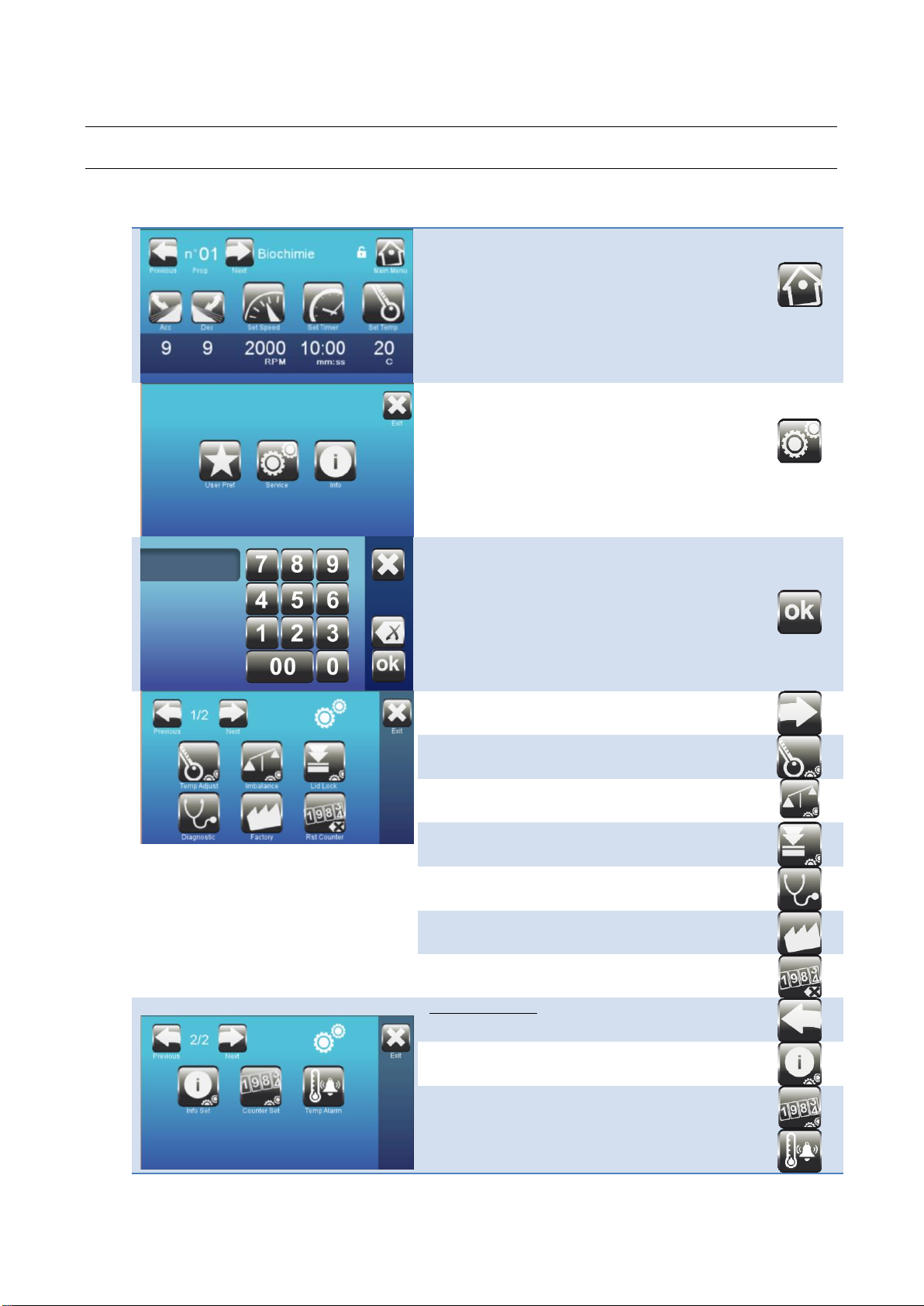
3.1 Access to the Technician Menu
Access the “Settings” menu using the following
keys:
This menu is reserved for authorized technicians.
Dial access code :
It is 4 last figures of serial number.
Ex : Serial number : 18C200RE1234
Access code : 1234
1st page of settings :
Next page
Setting the temperature probe
Setting the imbalance sensitivity
Setting the time delay of the lock
Auto-Diagnostic
Reset to factory settings
Clear the counters
2nd settings page
Previous page
Changing the internal numbers
Changing the counters
Over Temperature Alarm

Original Instructions - Rev.1.4 Service Manual–Lisa / Loreena Centrifuges 16/ 41
3.2 Setting the temperature probe
Access the temperature probe calibration
menu.
The upper value “Probe Temp.”
corresponds to the physical value measured
by the temperature sensor, located in the
lid.
The lower value “Displayed Temp.” is the
value displayed on the screen. This is the
temperature value of the samples in the
buckets, during a centrifugation cycle.
A correction of + /- 2°C is possible in the
case of deviation with the temperature of
the sample in the buckets.
Press the “-” or “+” keys to adjust the value.
Confirm by pressing ok.
3.3 Unbalancing Sensitivity Detection
The centrifuge has a reaction to the load balancing faults which may be different depending on the media on
which the centrifuge is placed. A calibration of the imbalance sensitivity is therefore necessary during
installation.
Required equipment: Use the reference balancing kit 71122002.
Access the unbalance sensitivity calibration
menu.
Equip a rotor swing-out and its 4 buckets in
the centrifuge.
Remove the inserts of the buckets.
Low threshold
1. Place the round 15 gram weight in one
of the buckets and close the lid,
2. Press the button “15gr”
3. The rotor accelerates until it stabilizes.
4. The centrifuge shakes, then the rotor
slows down.
5. The low threshold is then determined. It
appears under the button “15 gr”. (e.g.
480)
6. Open the lid and remove the 15 gram
weight.
High threshold
7. Place the 25 gram weight in the same
bucket.
8. Proceed in the same way as for the 15
gram weight.
9. The low threshold is then determined.
(e.g. “520”)
10.Open the lid and remove the 25 gram
weight.

Original Instructions - Rev.1.4 Service Manual–Lisa / Loreena Centrifuges 17/ 41
Average
11. Press on the Next button to average the
setting.
(e.g. [480+520]/2 = 500 )
The average value is displayed.
By default, the factory setting value is
500.
Check
The following steps are compulsory.
High threshold:
Do not adjust this threshold with a weight
greater than 25 gr. This would cause a breach
of warranty. The appliance has been
dimensioned for a maximum threshold of
25gr.
12.Place the 15 gr + 10 gr weights in a
bucket.
13. Start the cycle. 2000 rpm / 1 minute / 9
Acceleration / Braking 9
14. The centrifuge must stop during the
acceleration, and display the message
ERROR1:
The 25 gr imbalance is not tolerated.
Repeat the High threshold check 3 times:
ERROR1 must appear each time.
Low threshold:
15. Leave only a weight of 15 gr in a bucket.
16. Start the cycle. 2000 rpm / 1 minute / 9
Acceleration / Braking 9
17. The centrifuge should achieve the
desired speed and then slow down and
stop without the following error message
appearing: The 15 gr imbalance must be
tolerated.
Repeat the Low threshold check 3 times:
Each cycle should take place normally.
Note : This setting value is viewable in
HOME -> INFORMATION menu, at
SETTINGS paragraph.
Original Instructions - Rev.1.4 Service Manual–Lisa / Loreena Centrifuges 18/ 41
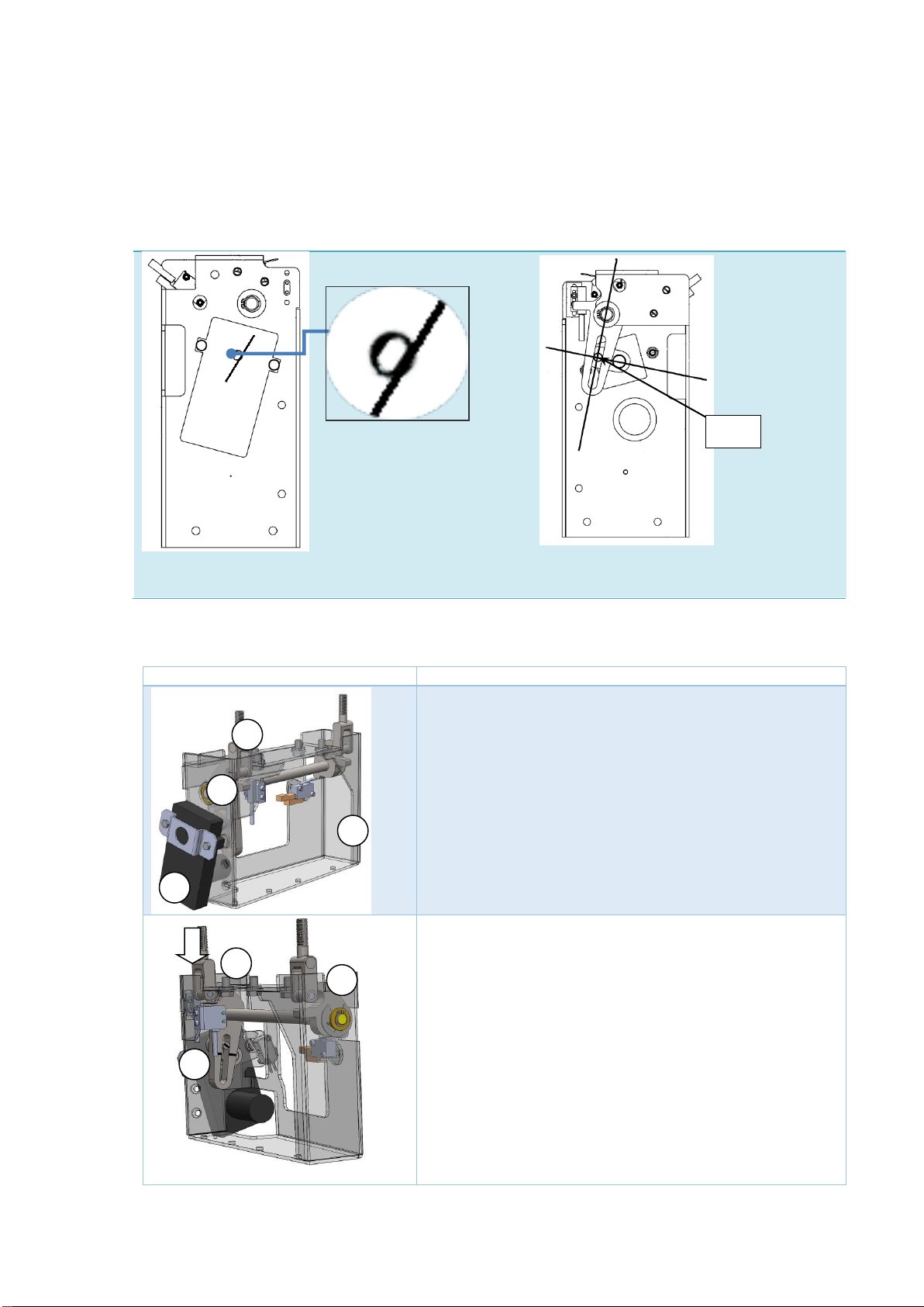
3.4 Setting the lock
3.4.1 .Lock Operation : LISA Model
The lock is in the locked position when the axis of the crankshaft and the oblong hole of the bolt are
perpendicular. A marking is carried out on the visible face, corresponding to this position.
Visible face - when the front panel is removed
Locked position identification marking
Internal face - after lock unit extraction.
Perpendicular position of the 2 axes
3.4.2 .Lock Operation : LOREENA Model
Locking steps : :
The lid is lowered manually.
The left strike of the cover (1) is detected by the approach sensor
(2).
The motor reducer (6) starts.
The open position sensor (8) changes to state 0.
The hooks (7) drive the 2 latches down.
When the left strike is detected, the closed position sensor of the
strike (3) goes to state 1.
90°
6
2
1
8
7
3
7
This manual suits for next models
12
Table of contents
Other AFi Laboratory Equipment manuals


Popular Laboratory Equipment manuals by other brands


Nakanishi
Nakanishi PRESTO II Operation manual

Elmi
Elmi MS-01 user manual

Tuttnauer
Tuttnauer T-Top 10 Operation and maintenance manual

Endress+Hauser
Endress+Hauser Liquistation CSF48 operating instructions

Waters
Waters Vion IMS QTof Overview and maintenance guide

cytiva
cytiva Ettan IPGphor Cup Loading Manifold user manual


