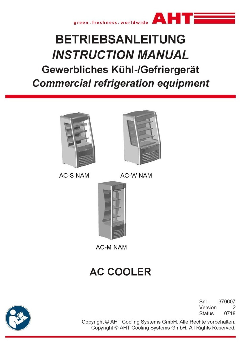
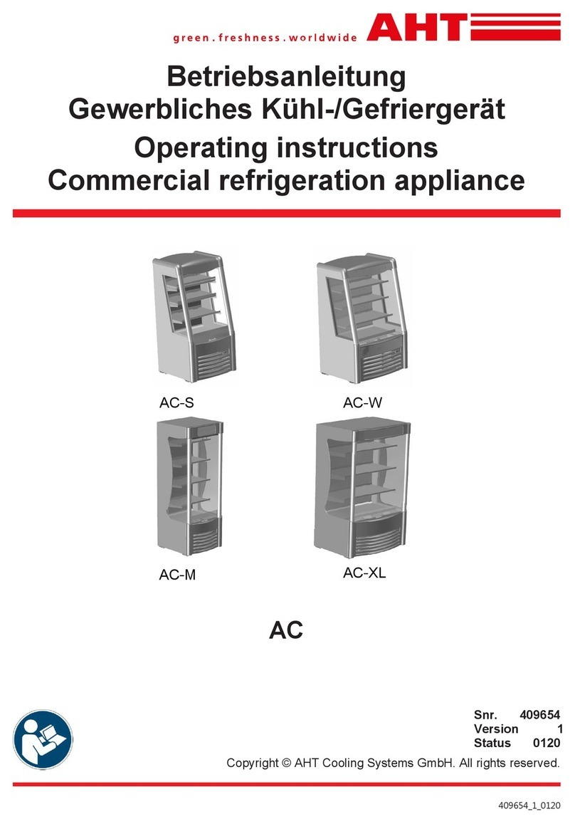
AHT AC-COOLER AC-S Manual

AC-COOLER
AC-S AC-M
Betriebs- und Wartungsanleitung
Operating and maintenance instructions
SNr. 293032
EL/0809
ISO 9001 (2000), ISO 14001
AC-S AC-W AC-M AC-XL
EL/0112
ISO 9001 (2008), ISO 14001 (2004)

AHT Cooling Systems GmbH
D
GB
IT
FR
NL
ES
P
DK
FIN
S
N
AC-Cooler
Betriebs- und
Wartungsanleitung
Originalbetriebsanleitung
3
AC-Cooler
Operating and
maintenance instructions
Translation of the
original instructions 9
AC-Cooler
Istruzioni d‘uso e
manutenzione
Traduzione delle
istruzioni originali 15
AC-Cooler
Manuel d‘utilisation
et d‘entretien
Traduction du mode
d’emploi original 22
AC-Cooler
Gebruiks- en
onderhoudsaanwijzing
Vertailing van de originele
gebruikershandleiding 28
AC-Cooler
Instrucciones de funciona-
miento y mantenimiento
Traducción de las instruc-
ciones de uso originales 35
AC-Cooler
Instruções de Utilização e
Manutenção
Tradução do manunal de
instruções original 41
AC-Cooler
Drifts- og
vedligeholdelsesvejledning
Oversættelse af den originale
driftsvejledning 47
AC-Cooler
Käyttö- ja huolto-ohje
Käännös alkuperäisestä
käyttöohjeesta 54
AC-Cooler
Bruks- och
underhållsanvisning
Översättning av original-
bruksanvisningen 61
AC-Cooler
Drifts- og
vedlikeholdsveiledning
Oversettelse av original
bruksanvisning 68
AC-Cooler
Navodila za delovanje in
vzdrževanje
Prevod izvirnega navodila
za uporabo 75
AC-Cooler
Uputa za uporabu i
održavanje
Az erediti használati
utasitás forditása 82
HR
SL
CZ
SK
PL
EST
LT
LV
H
RUS
RO
GR
TR
BG
257
AC-Cooler
Návod k
obsluze a údržbě
Překlad originálního
návodu k použití 89
AC-Cooler
Návod na
použitie a údržbu
Preklad originálneho
návoduna použitie 96
AC-Cooler
Instrukcja obsługi
i konserwacji
Tłumaczenie oryginalnej
instrukcji obsługi 103
AC-Cooler
Kasutus- ja
hooldusjuhend
Originaalkasutusjuhendi
tõlge 109
AC-Cooler
Naudojimo ir priežiūros
instrukcija
Originalaus naudojimo
instrukcijos vertimas 116
AC-Cooler
Apkalpes un apkopes
instrukcija
Lietošanas instrukciju tulko-
jums no oriģinālvalodā123
AC-Cooler
Üzemeltetési és
karbantartási útmutató
Az eredeti használati
utasitás fordítása 130
AC-Cooler
Эксплуатации техническому
обслуживанию
Перевод оригинальной
инструкции 136
AC-Cooler
Instrucţiunile de exploatare
şi întreţinere
Traducere a manualului
de exploatare originale 143
AC-Cooler
Οδηγίες λειτουργίας και
συντήρησης
Μετάφραση του πρωτοτύπου
των οδηγιών 150
AC-Cooler
Kullanıum ve Bakım Kılavuzu
Orjinal kullanım kılavuzunun
çevirisi 157
AC-Cooler
164

3
AC-COOLER
AC-S Typ B910 (B)
AC-M Typ B911 (B)
AC-XL Typ B912 (B)
INHALTSVERZEICHNIS
11. Allgemeine Angaben .................................................................................... 2
12. Leistungsschild und Seriennummer ............................................................. 2
13. Anwendung .................................................................................................. 2
14. Auspacken und Handhabung ....................................................................... 2
15. Aufstellung.................................................................................................... 2
16. Elektrischer Anschluss ................................................................................. 3
17. Inbetriebnahme und Funktion....................................................................... 3
18. Elektronischer Regler DIXELL XR60CX....................................................... 3
19. Bedienung der Nachtabdeckung (Rollo)....................................................... 4
10. Wartung und Reinigung................................................................................ 4
11. Längere Außerbetriebnahme des Gerätes................................................... 4
12. Lampenwechsel ........................................................................................... 4
13. Entsorgung ................................................................................................... 5
14. Was tun wenn .............................................................................................. 5
15. Explosionszeichnungen und Teileliste.......................................................... 5
16. Stromlaufplan ............................................................................................... 6
17. Konformitätserklärung .................................................................................. 6
Sicherheitshinweise
wBitte lesen Sie diese Bedienungs- und Wartungsanleitung aufmerksam durch und geben Sie diese auch an
andere Personen, die mit der Handhabung und dem Gebrauch dieses Gerätes betraut sind weiter! Die Be-
dienungs- und Wartungsanleitung muss während der erwarteten Lebensdauer aufbewahrt werden und stän-
dig am Gerät verfügbar sein.
wKontrollieren Sie das Gerät sofort nach der Anlieferung auf Transportschäden und Funktion! Das Gerät darf
nur betrieben werden, wenn alle Sicherheitseinrichtungen vorhanden und funktionsfähig sind.
wDas Gerät darf nur in Gebrauchslage (eben, waagrecht, mit Öffnung nach vorne) betrieben werden. (Bitte
beachten Sie die Aufstellhinweise.) Wird das Gerät beim Transport geneigt, warten Sie mit der Inbetriebnah-
me min. 2 Stunden, um Defekte zu vermeiden.
wDas Gerät beginnt sofort nach dem Anlegen der Betriebsspannung zu arbeiten. Beachten Sie die Leistungs-
angaben am Typenschild sowie die einschlägigen örtlichen Elektrosicherheitsvorschriften, bevor Sie das Ge-
rät an die Stromversorgung anschließen.
wGerät nicht über 70°C (158°F) erwärmen. Setzen Sie das Gerät nicht der direkten Sonnenbestrahlung aus.
Die Umgebungstemperatur darf allerdings auch nicht unter 16°C (61°F) abfallen.
wDie Reinigung mit Hochdruckreiniger (Dampfstrahler) ist verboten.
wArbeiten an der elektrischen Anlage und am Kältesystem dürfen nur von Fachkräften durchgeführt werden.
Wird dies nicht beachtet, erlöschen sämtliche Garantie- und Haftungsansprüche.
wSpitze Gegenstände können die Glasscheiben zerkratzen und in weiterer Folge zerstören (Sicherheitsglas).
wFür die Entsorgung prüfen Sie bitte Ihre Verpflichtungen gemäß den nationalen WEEE-Bestimmungen und
führen Sie das Gerät bitte dem örtlichen WEEE-Entsorgungspartner zu.
wAchten Sie darauf, dass die Rohrleitungen nicht beschädigt werden (Gerät nicht anbohren).
4
4
4
4
4
5
5
5
6
6
7
7
7
7
7
7
8
Das Gerät beginnt nach einer kurzen Verzögerung (ca. 1 min) nach dem Anlegen der Betriebsspannung zu
arbeiten. Beachten Sie die Leistungsangaben am Typenschild sowie die einschlägigen örtlichen Elektrosicher-
heitsvorschriften, bevor Sie das Gerät an die Stromversorgung anschließen.
Sicherheitshinweise
• Bitte lesen Sie diese Bedienungs- und Wartungsanleitung aufmerksam durch und geben Sie diese auch an andere Personen,
die mit der Handhabung und dem Gebrauch dieses Gerätes betraut sind weiter! Die Bedienungs- und Wartungsanleitung
muss während der erwarteten Lebensdauer aufbewahrt werden und ständig am Gerät verfügbar sein.
• Das Betreiberpersonal ist durch den Marktleiter zu unterweisen.
• Personen (einschließlich Kinder), die aufgrund ihrer physischen, sensorischen oder geistigen Fähigkeiten, Unerfahrenheit oder
Unkenntnis nicht in der Lage sind das Gerät sicher zu benutzen, sollten dies nur unter Aufsicht oder Anweisung einer verant-
wortlichen Person tun. Insbesondere Kinder sollten beaufsichtigt werden, damit sie nicht mit dem Gerät spielen.
• Kontrollieren Sie das Gerät sofort nach der Anlieferung auf Transportschäden und Funktion! Das Gerät darf nur betrieben
werden, wenn alle Sicherheitseinrichtungen vorhanden und funktionsfähig sind.
• Das Gerät darf nur in Gebrauchslage (ebener Untergrund, mit Öffnung nach vorne) betrieben werden. (Bitte beachten Sie die
Aufstellhinweise.) Wird das Gerät beim Transport geneigt, warten Sie mit der Inbetriebnahme min. 2 Stunden, um Defekte zu
vermeiden.
• sofort nach dem Anlegen der Betriebsspannung zu arbeiten. Beachten Sie die Leistungsangaben am Typenschild sowie die
einschlägigen örtlichen Elektrosicherheitsvorschriften, bevor Sie das Gerät an die Stromversorgung anschließen.
• Gerät nicht über 70°C (158°F) erwärmen. Setzen Sie das Gerät nicht der direkten Sonnenbestrahlung aus. Die Umgebungs
temperatur darf allerdings auch nicht unter 16°C (61°F) abfallen.
• Die Reinigung mit Hochdruckreiniger (Dampfstrahler) ist verboten.
• Arbeiten an der elektrischen Anlage und am Kältesystem dürfen nur von Fachkräften durchgeführt werden. Wird dies nicht
beachtet, erlöschen sämtliche Garantie- und Haftungsansprüche.
• Spitze Gegenstände können die Glasscheiben zerkratzen und in weiterer Folge zerstören (Sicherheitsglas).
• Für die Entsorgung prüfen Sie bitte Ihre Verpflichtungen gemäß den nationalen WEEE-Bestimmungen und führen Sie das
Gerät bitte dem örtlichen WEEE-Entsorgungspartner zu.
• Achten Sie darauf, dass die Rohrleitungen nicht beschädigt werden (Gerät nicht anbohren).
• Es dürfen keine Dosen mit brennbarem Gas als Treibmittel im Gerät gelagert werden.
• Es dürfen keine Gegenstände wie z.B. Flaschen auf dem Kühlmöbel abgestellt werden.
• Bei einem Glasbruch der lagernden Flaschen im Innenraum des Gerätes die Glasteile sorgfältig aus dem Warenraum
entfernen. Vorsicht Verletzungsgefahr!
• Das Gerät ist regelmäßig auf Fremdgegenstände im Warenraum und auf Beschädigungen (spitze Kanten) zu kontrollieren.
AC-COOLER
Verkaufskühlmöbel „Kühlen”
Refrigerated Display Cabinet „Cooling“
AC-S Typ B 910, B 910B
AC-M Typ B 910, B 910B
AC-XL Typ B 912, B 912B
AC-W Typ B 913, B 913B

4
4
AHT Cooling Systems GmbH
1. Allgemeine Angaben
Vor der Aufstellung und Inbetriebnahme dieses Gerätes
sind die bei Ihnen geltenden gewerberechtlichen Be-
stimmungen zu beachten.
AHT-Geräte sind frei von PCB, PCT, Asbest, Formalde-
hyd, Cadmium und benetzungsstörenden Substanzen.
Das Kältemittel R404A ist vom Kyoto-Protokoll erfasst
und weist ein Treibhauspotential (GWP) von 3784 auf.
2. Leistungsschild und Seriennummer
Für die Installation und Wartung sind die Angaben auf
dem "Leistungsschild" zu beachten. Dieses befindet
sich oben auf der Innenseite (Innenraum) des Gerätes.
Angaben über Seriennummer, Gerätetyp, Kältemittel
sowie elektronischen Daten finden Sie auf dem Leis-
tungsschild.
3. Anwendung
ACHTUNG: Nicht auf das Gerät steigen.
Betreiben Sie das Gerät in einem Temperaturbereich
von 16°C (60,8F) bis max. 25°C (77°F), bei einer
maximalen Luftfeuchtigkeit von 60% rH, laut Klimaklas-
se 3.
Dieses Gerät ist ausschließlich für die Aufbewahrung
und Präsentation von gekühlten, abgepackten bzw. in
Flaschen oder Dosen abgefüllten Lebensmittel geeig-
net.
ACHTUNG: Eine andere oder darüber hinaus-
gehende Nutzung des Gerätes gilt als nicht
bestimmungsgemäß.
Befüllen Sie das Gerät maximal nur bis zur Stapelmar-
ke (siehe Kap. 7). Blockieren Sie keinesfalls interne Lüf-
tungsgitter, da sonst die Luftzirkulation nicht aufrecht
erhalten werden kann.
4. Auspacken und Handhabung
ACHTUNG: Um das Gerät vor Schäden zu be-
wahren, darf das Gerät nur in Gebrauchslage
transportiert und gelagert werden. Nichtbeach-
tung hat den Verlust der Gewährleistung zur
Folge.
Wird das Gerät beim Transport geneigt, warten
Sie mit der Inbetriebnahme mind. 2 Stunden, um
Defekte zu vermeiden.
Vor und beim Auspacken des Gerätes muss eine Sicht-
kontrolle durchgeführt werden, um eventuelle Trans-
5.
5. Aufstellung
ACHTUNG: Die Stellfüße an der Unterseite müssen
unbedingt ausgerichtet sein, sonst besteht
Kippgefahr!
ACHTUNG: Gerät keiner direkten Sonnen-
bestrahlung aussetzen.
Das Gerät nicht im Freien aufstellen.
Halten Sie unbedingt den vorgeschriebenen Ab-
stand zur Rückwand (10cm, 3.94“) ein! Montieren
Sie hierzu den mitgelieferten Wandabstandhalter an
der Rückseite des Gerätes (siehe Montageanleitung).
Eine „Rücken an Rücken“ Platzierung ohne Zwi-
schenwand ist nicht zulässig!
Die Abluftöffnungen an der Oberseite/Rückseite des
Geräts müssen freigehalten werden, deshalb keine
Gegenstände auf das Gerät stellen.
Am Gerät befinden sich an der Unterseite Transport-
rollen zur leichteren Manipulation (Ortsveränderung)
des Geräts und Stellfüße an der vorderen Unterseite
zur stabilen Aufstellung (siehe unterhalb).
Stellfuß:
Achten Sie auf stabile und horizontale Ausrichtung
des Gerätes. Dazu muss der Stellfuß höhenverstellt
werden. Die beiden Stellfüße befinden sich an der
vorderen Unterseite unter dem vorderen Lüftungsgit-
ter, neben den Transportrollen. Der kunststoffbe-
schichtete Stellfuß kann durch Rechts- und Linksdre-
hen höhenverstellt werden (siehe Detailbeschrei-
bung unten). Das Gerät muss dabei nicht geöffnet
werden.
Detailbeschreibung Stellfuß:
Stellfuß
Höhenverstellung
Vorderes Lüftungsgitter
Produktfach
Transportrolle
Innenraum
Detail
A
A
portschäden festzustellen. Bitte achten Sie auf Beulen,
Kratzer, etc.
Eventuelle Schäden sind sofort AHT / Vertriebspartner
zu melden. Im Übrigen gelten die AHT Geschäftsbedin-
gungen.
Vor Entsorgung des Verpackungsmaterials, dieses bitte
auf lose Funktionsteile kontrollieren.
Befüllen Sie das Gerät maximal bis zum Beginn des Luft-
eintrittsgitter am Innenraumboden oder wenn vorhanden
bis zur Stapelmarke (siehe Kap. 7). Blockieren Sie kei-
nesfalls interne Lüftungsgitter, da sonst die Luftzirkula-
tion nicht aufrecht erhalten werden kann.
Der einwandfreie Zustand des Kühlgerätes und die be-
stimmungsgemäße Verwendung sind durch das unter-
wiesene Betreiberpersonal regelmäßig zu kontrollieren.
Die Geräte müssen auch dahingehend kontrolliert wer-
den, dass die Waren, die durch Dritte (unsachgemäß)
eingelagert wurden, entfernt werden.
Luftschallemissionen der Geräte < 70 dB(A)
Bei lauten Geräuschen und/oder starken Vibrationen am
Gerät, ist ein Servicetechniker zu kontaktieren.
Die Gerätegewichte sind in den Prospektdatenblättern
aufgeführt. Diese können bei AHT bezogen werden.
Für die Installation und Wartung sind die Angaben auf-
dem „Leistungsschild” zu beachten. Dieses befindet sich
auf der Rückseite (außen) des Gerätes.
Angaben über Seriennummer, Gerätetyp, Kältemittel so-
wie elektronischen Daten finden Sie auf dem Leistungs-
schild.
Betreiben Sie das Gerät in einem Temperaturbereich wie
am Leistungsschild angegeben.
Dieses Gerät ist ausschließlich für die Aufbewahrung
und Präsentation von gekühlten, abgepackten bzw. in
Flaschen oder Dosen abgefüllten Lebensmittel geeignet.
4. Auspacken und Handhabung
ACHTUNG: Um das Gerät vor Schäden zu be-
wahren, darf das Gerät nur in Gebrauchslage
transportiert und gelagert werden. Nichtbeach-
tung hat den Verlust der Gewährleistung zur
Folge.
Wird das Gerät beim Transport geneigt, warten
Sie mit der Inbetriebnahme mind. 2 Stunden, um
Defekte zu vermeiden.
Vor und beim Auspacken des Gerätes muss eine Sicht-
kontrolle durchgeführt werden, um eventuelle Trans-
Wird das Gerät beim Transport
geneigt, warten Sie mit der Inbetriebnahme
mind. 2 Stunden, um Defekte zu vermeiden.
ACHTUNG:
5.
5. Aufstellung
ACHTUNG: Die Stellfüße an der Unterseite müssen
unbedingt ausgerichtet sein, sonst besteht
Kippgefahr!
ACHTUNG: Gerät keiner direkten Sonnen-
bestrahlung aussetzen.
Das Gerät nicht im Freien aufstellen.
Halten Sie unbedingt den vorgeschriebenen Ab-
stand zur Rückwand (10cm, 3.94“) ein! Montieren
Sie hierzu den mitgelieferten Wandabstandhalter an
der Rückseite des Gerätes (siehe Montageanleitung).
Eine „Rücken an Rücken“ Platzierung ohne Zwi-
schenwand ist nicht zulässig!
Die Abluftöffnungen an der Oberseite/Rückseite des
Geräts müssen freigehalten werden, deshalb keine
Gegenstände auf das Gerät stellen.
Am Gerät befinden sich an der Unterseite Transport-
rollen zur leichteren Manipulation (Ortsveränderung)
des Geräts und Stellfüße an der vorderen Unterseite
zur stabilen Aufstellung (siehe unterhalb).
portschäden festzustellen. Bitte achten Sie auf Beulen,
Kratzer, etc.
Eventuelle Schäden sind sofort AHT / Vertriebspartner
zu melden. Im Übrigen gelten die AHT Geschäftsbedin-
gungen.
Vor Entsorgung des Verpackungsmaterials, dieses bitte
auf lose Funktionsteile kontrollieren.
• Das Gerät nicht im Freien aufstellen.
• Halten Sie unbedingt den vorgeschriebenen Ab-
stand zur Rückwand ein! Montieren Sie hierzu den
mitgelieferten Wandabstandhalter an der Rück-
seite des Gerätes (siehe Montageanleitung). Eine
„Rücken an Rücken“ Platzierung ohne Zwischen-
wand ist nicht zulässig!
• Die Abluftöffnungen an der Oberseite/Rückseite des
Geräts müssen freigehalten werden, deshalb keine
Gegenstände auf das Gerät stellen.
• Am Gerät befinden sich an der Unterseite Transport-
rollen zur leichteren Manipulation (Ortsveränderung)
des Geräts.
Gerät keiner direkten Sonnenbestrah-
lung aussetzen.

AHT
Cooling
Systems
GmbH
•
Auf
eine
stabile
und
waagrechte
Ausrichtung
des
Ge
rätes
achten.
•
Bei
den
Modellen
AC S
und
AC M
ist
je
Produktfach
eine
Beladung
von
maximal
35kg,
beim
AC W
40kg
und
beim
AC XL
85kg
zulässig.
•
Zugluft
und
größere
Wärmeeinstrahlung
am
Aufstell
ort
vermeiden.
Geräte
nicht
vor
Heizkörpern,
Heizge
räten
und
unter
Luftauslässen
platzieren.
•
Wärmequellen
nicht
in
das
Gerät
richten.
•
Jegliche
Wärmestrahlung
in
das
Gerät
führt
zu
erhöh
ten
Betriebskosten
und
kann
die
Leistungsfähigkeit
des
Gerätes
beeinträchtigen.
|ACHIUNG:
|
Beim
AC-Cooler
mit
Doppelscheiben
Isolierglas
ist
eine
maximale
Aufstellungsh he
von
2000
m
über
Meeresniveau
erlaubt.
6.
Elektrischer
Anschluss
|
ACHTUNG?]
Für
die
Elektroinstallationen
sind
die
nationalen
Normen
und
Sicherheitsvorschriften
einzuhalten
|ACHTUN
g
7|
Netzspannung
und
Netzfrequenz
müssen
mit
den
am
Typenschild
des
Gerätes
an
gegebenen
Nennwerten
übereinstimmen.
|
a
CHTUNG?1
Arbeiten
am
elektrischen
System
dürfen
nur
von
Fachkräften
durchgeführt
werden.
Die
einschlägigen
rtlichen
Sicherheitsvorschrif
ten
sind
zu
beachten.
|
ACHTUNG]
Wenn
die
Netzanschlussleitung
be
schädigt
wird,
muss
diese
durch
AHT
oder
den
AHT
Kundendienst
ersetzt
werden.
•
Das
Gerät
ist
ein
steckerfertiges
Kompaktgerät.
•
Das
Netzkabel
befindet
sich
hinten
am
Gerät.
•
Absicherung
mit
16
A
(träge)
verwenden
(siehe
tech
nische
Daten
am
Leistungsschild).
(für
USA
mit
15A)
•
Die
Verwendung
von
Verlängerungskabeln
bzw.
Mehr
f
fachs
t
teckd
o
o
s
sen
so
l
l
l
lte
nach
Möglichkeit
ver
r
mieden
werden.
Wenn
es
unbedingt
nötig
ist,
ist
da
rauf
zu
achten,
dass
die
verwendeten
Kabel
ei
i
nen
Mindestquerschnitt
von
2,5
mm
2
2
entspricht
für
USA:
14
AWG)
nicht
unterschreiten.
•
Geräte
nur
an
Schutzkontaktsteckdose
mit
Erdungs
kontakt
und
eigenem
Netzstromkreis
anschließen.
•
Es
dürfen
maximal
2
Geräte
vom
Gerätetyp
AC S
und
AC M
und
AC W
an
einen
Stromkreis
ange
schlossen
werden.
Beim
AC XL
und
bei
Geräten
mit
120V
Netzspannung
darf
nur
ein
Gerät
an
einem
Stromkreis
angesteckt
werden.
Lastabwurfschaltungen
bzw.
Geräteabschaltungen
sind
nicht
zulässig,
da
dadurch
Störungen
auftreten
können.
Bei
Nichtbeachtung
dieser
Sicherheitsvorschriften
sind
Ansprüche
aus
dem
Titel
der
Gewährleistung
und/oder
des
Schadenersatzes
ausgeschlossen.
7.
Inbetriebnahme
und
Funktion
/N|
a
CHTUNG:
|
Bei
Anlegen
der
Betriebsspannung
(Netzstecker
einstecken
-
siehe
Kapitel
6
)
be
ginnt
das
Kühlaggregat
nach
e
iner
ku
r
zen
Ver
z gerung
(ca.
1
min)
zu
arbeiten.
Das
Gerät
sollte
vor
Inbetriebnahme
(nach
Aufstellung
siehe
Kap.
5)
eine
Mindesttemperatur
von
+16°C
(60,8°F)
aufweisen,
ansonsten
muss
das
Gerät
an
die
normale
Raumtemperatur
angeglichen
werden.
Stellen
Sie
sicher,
dass
die
Waren
die
Luftzufuhr
ffnungen
nicht
versperren.
Bei
speziellen
k
limatischen
Bedingungen
mit
hoher
Luft
feuchtigkeitkanneineKondensatbildung
im
Innenraum
des
Gerätes
bzw.
an
den
Luftaustrittsöffnungen
oben
vorkommen
und
beeinträchtigt
nicht
die
Kühlfunktion
des
Gerätes.
Abtauun
g
sarten
(siehe
Kap.
8):
Automatische
Abtauung
Manuelle
Abtauung
Lufteintrittsgitter
am
Innenraumboden
oder
Stapelmarke
Die
Beladung
der
Geräte
darf
nur
bis
zum
Beginn
des
Lufteintrittsgitte
r
am
Innenraumboden
oder
wenn
vor
handen
bis
zu
den
Stapelmarken
erfolgen.
Zwischen
vorderer
Trennscheibeund
Stapelmarke
darf
keine
Ware
gelagert
werden,
da
sonstder
Kühlkreislauf
gestört
wird
und
die
eingestell
te
Lagertemperatur
nicht
gewährleistet
werden
kann.
I
ACHTUNG?
Ein
m gliches
Auslaufen
des
Abtauwas
ser
oder
Flüssigkeiten
aus
undichten
Flaschen
aus
dem
Gerät
kann
auftreten
und
sollte
dann
entspre
chend
entfernt
werden,
da
ansonsten
Ausrutschge
fahr
besteht.
8.
Elektronischer
Regler
DIXELL
XR60CX
Das
Gerät
ist
miteiner
ele
ktronischen
Steuerung
aus
gestattet.
Alle
Programmierparameter
sind
Werksein
stellungen
und
dürfenausschließlich
von
autorisiertem
Servicepersonalgeändert
werden.(Mit
Ausnahmeder
Sollwerttemperatur)Das
Gerätstartetnach
Anlegen
der
Betriebsspannung
mit
einer
kurzen
Verzögerung
(ca.
1
min)
den
Betrieb.
Hand
Abtauungeinleiten
Änderung
des
Sollwertes
(AUF)
"V
Änderung
des
Sollwertes
(AB)
(I)
Ein
oder
Ausschalten
der
Kühlfunktion
(Standby Taste)
Ein
oder
Ausschalten
des
Innenlichtes
(Licht Taste)
Hauptschalter:
beim
USA-Gerät
an
der
Rückseite
im
Lüftungsgitter
5

AHT
Cooling
Systems
GmbH
Temperaturkontrolle
Einstellungen:
Die
Temperaturkontrolle
wird
im
Werk
vor
eingestellt,
damit
d
i
e
Temperatur
der
gekühlten
Produkte
zwischen
+2°Cund
+7°C
(35,5°F
und
41°F)liegt.
Bei
Bedarf
(Wetter
oder
Standort)
kann
die
Kühltemperatur
verändert
werden.
Lesen
SiehierzudenPunkt
Sollwert
ändern.
Anzeige:
Die
Temperaturanzeige
gibt
nur
die
Temperatur
im
Innerendes
Kühlgerätes
an.Die
Temperaturkann
zwischen
+2°C
und
+7°C(35,5°Fund
41°F)schwanken.
Bei
der
Abtau
ung
kann
die
Temperatur
+7°C
(41°F)in
der
Anzeige
über
steigen,
diegelagertenProduktewerdenjedochweiterhinauf
einer
Temperatur
unterhalb
+7°C
(41°F)
gehalten.
Automatische
Abtauung:
Die
Abtauungdes
Kühlgerätes
er
folgtautomatisch
während
des
Gerätebetriebes.
Manuelle
Abtauung:
Bei
Bedarfkann
eine
manuelle
Abtau
ung
eingeleitet
werden.
Dazu
die
Abtau Taste
mind.
2s
ge
drückthalten.Nach
erfolgter
Abtauung
kehrt
dasGerät
auto
matisch
in
den
normalen
Betriebszustand
zurück.
Den
Sollwert
einsehen
1x
Ta
s
t
e
SET
:
Der
So
llwert
wird
angezeigt
E
XIT:
15s
wa
r
t
en
odernochmai
1x
SET
Tastedrücken
K
ollwert
änd
u
rn
1.
Taste
SET
mind.
2s
gedrückt
halten
2.
Sollwert
wird
angezeigt
und
LED Symbol
°C
blinkt
3.
AUF/AB
Taoten
zum
Ändern
der
Vorgabe
4.
Zur
Bestätigung
der
Vorgxbe
1x
SET
Taste
drücken
oder
15s
warten
9.
Bedienung
der
Nachtabdeckung
(Rollo)
Tagbetrieb:
Nachtabdeckung
offen
Nachtbetrieb:
Nachtabdeckung
geschlossen
Beim
Schließen/Öffnen
der
Nachtabdeckung
erfolgt
eine
auto
matische
Abschaltung/Einschaltung
der
Innenbeleuchtung
des
Kühlgerätes.
Schließen
der
Nachtabdeckung:
•
Nachtabdeckung
am
Griff
nach
unten
ziehen
bis
zur
Halterung
•
Einhängen
des
Griffs
beidseitig
in
die
Halterung
bis
zum
Anschlag
drücken
Öffnen
der
Nachtabdeckung:
•
Aushängen
des
Griffs
durch
ziehen
aus
der
Halterung
•
Loslassen
des
Griffs,
Nachtabdeckung
rollt
sich
bis
zur
Endposition
ein
10.
Wartung
und
Reinigung
A
A
chtung
?]
Geräte
nicht
über
70°C
(158°F)
er
wärmen
und
keiner
übermäßigen
Hitzeeinwir
kung
aussetzen
(Heizstrahler,
etc.)!
A
|
ACHTUNG]
Die
Reinigung
mit
Hochdruckreiniger
(Dampfstrahler)
ist
verboten.
•
Das
Gehäuse
außen
von
Zeit
zu
Zeit
mit
einem
trockenen
Lappen
abreiben
•
Die
Glasscheiben
mit
handelsüblichem
Fenster
reinigungsmittel
säubern
AACHTUNG:
|
Da
FensterreinigungsmittelAnteile
an
L sungsmittel
enthalten,
sollte
der
Kontakt
mit
Kunststoffflächen
vermieden
werden.
Im
speziellendürfen
keine
Rückständevom
Fenster
reinigungsmittel
auf
den
Kunststoffteilen
ver
bleiben.
Grundreinigu
ng
(w che
ntlic
h
oder
nach
Bed
ar
f
):
•
Ware
in
ein
anderes
Gerät
umlagern
•
N
e
tzstecker
ziehen
•
B
e
i
BeearfRegalböden
a
n
heben
und
h
e
rau
s
n
e
hmen
•
Verzichte
n
Sie
auf
grobe
oder
leicht
entzündliche
Reinigungsprodukte,
um
Schäden
zu
vermeiden.
•
Flächen
und
vorderes
Lüftungsgitter
mit
einem
feuch
ten,
saube
r
en
Tuch
und
mit
neutraler
Seife
reinigen.
Verwenden
Sie
zur
Reinigung
k
eine
scharfe
n
Gegen
stände.
•
Reinigung
de
n
herausgenommenen
Regalböden
mit
feuchtem,
s
a
ub
e
r
e
n
Tuch
und
neutraler
Seife.
•
R
e
inigung
der
Glasflächen
mit
Glasreiniger
•
Trockn
en
Sie
da
s
Ge
rät
und
R
e
galböden
mit
einem
Tuch
•
B
e
i
Bgdarf
Regalböde
n
einlegen
•
N
e
tzstenker
einstecken
und
2
St
d
.
laufen
lassen.
•
Waren
einlagern
6

AHT
Cooling
Systems
GmbH
Reinigung
des
Innenraumes
Lüfterbereich
•
Anheben
des
Innengitters
•
Innengitter
nach
hinten
ziehen
•
Bei
Bedarf
den
Innenraum
im
Bereich
Lüfter
mit
ei
nem
Tuch
reinigen
•
Innengitter
montieren
geschlossener
Lüfterbereich
T
12.
Lampenwechsel
Der
Lampenwechsel
(Tausch
der
Leuchtstoffröhren/
LED Leuchten)
darf
nur
durch
eine
autorisierte
Fachkraft
erfolgen!
lACHTUNG^
Bei
Lampenbruch
Glasteile
sorgfältig
aus
dem
Warenraum
entfernen.
13.
.
Entsorgun
g
|AC
H
T
U
NG
Wärme
sto
G
d
äm
mung
Polyurethans
A
haum
(
PU)
mit
Kohlenstoffd
f
oxid
X".
D
as
Gerä
t
nicht
zum
normalen
Müll
geben,
sondern
prüfen
Sie
bitte
Ihre
Verpflicht
ungen
gemäß
d
e
n
nat
i
o
n
alen
WEEE Bestimmungen
und
dem
örtli
ch
en
WEEE Entsorgungs
pa
r
tner
.
D
a
rauf
a
ch
ten,
d
ass
dabei
die
Rohr
leitungen
n
icht
beschädigt
werden.
14.
Was
t
un
wenn
...
/^lACHTUNG:
!
Arbeiten
an
der
elektrischen
Anlage
und
am
Kältesystem
dürfen
nur
von
Fachkräften
d
urchgeführt
werden.
Das
Gerät
wurd
e
im
AHT
Prüfzentrum
sorgfältig
auf
Leistung
und
Sicherheit
geprüft.
Sollte
trotzdem
einmal
eine
Störung
au
f
tr
e
ten,
überprüfen
Sie
bi
t
te
zunächst
fo
X
endes:
•
Ist
d
e
r
Netzst
e
cker
eingesteckt?
•
Ist
das
Gerät
eingeschaltet
(siehe
Kap.
8
Drücken
der
Standby Taste)?
•
Liegt
Spannung
an
der
Steckdose
an?
•
Ist
die
Anzeige
aktiv?
Lampe
leuchtet
nicht
(siehe
Kap.
8)
11.
Längere
Auße
p
betriebnahme
des
Gerätes
•
Alle
Waren
auslmgern
•
Netzstecker
ziehen
•
Reinigung
des
Geräts
gemäß
Gmnd
und
Hauptreini
gung
Beruht
die
Störung
auf
keiner
dieser
Ursachen,
Anruf
beim
Kundendienst
/
Servicepartner.
15.
Explosionszeichungen
und
Teileliste
Explosionszeichnungen
und
Teilelisten
liegen
den
Service
partnern
vor.
16.
Konformitätserklärung
/
Declaration
of
Conformity
©
KONFORMITÄTSERKLÄRUNG
Der
Hersteller,
die
Firma
AHT
Cooling
Systems
GmbH
Werksgasse
57
8786Rottenmann,Austria
erklärt,
dass
diein
dieserBe
t
riebs und
Wartungsanleitung
aufSeite
langeführtenGeräte
mitdenBestimmungen
derEWR
Richtlinien
2004/108/
EGund
2006
/
42/EGübereinstimmen.
EN
378 1:2008
+
Ber.1:2010;
EN
378 2:2008+A1:2009;
EN
378 3:2008;
EN
378 4:2008
+
Ber1:2010;
ENISO
23953 1:2005;
EN
ISO
23953 2:2005;
EN
60335 1
:2002
+
A1
1
:2004
+
A1:2004
+
A1
2:2006
+
Cor.:2006
+
A2:2006
+
Cor.:2007 01
+
Cor.:2007
02
+
A13:2008
+
Cor.:2009
+
Cor.:2010
+A14:2010;
EN
60335 2 89:2010;EN
62233:2008
+
Ber1:2008;EN
55014 1:2006
+
A1:2009;EN
55014 2:1997
+
Corrigendum
1997
+
A1:2001
+
A2:2008;
EN
55015:2006
+
A1:2007
+
A2i2009;
EN
61000 3
2:2006
+
A1:2009
+
A2:2009;
EN
61000 3 3:2008;
EN
61000 3 11:2000;
EN
ISO
14121 1:2007
/
)
CE Bevollmächtigter:
ThomasMayr,
AbteilungEntwicklung;
AHT
Cooling
Systems
GmbH,
Werkgasse
57,8786
Rottenmann
Zusätzlich
für
PROPAN
R290
Geräte:
IEC
/
EN
60079 15:2010
C
Entwicklungsleiter
R&
DMa
n
ager
R
e
spogs
ible
recherche
e
t
t
^i^v
elopch
m
chl
Rottenmann,
03.10.2011
in.-ßeschättsführer
[
X
^e
tst
i
üc
i
effi
cer
t
t
i
on
techn
ique
7

8
17. Stromlaufpläne / Circuit Diagrams
S1 - Hauptschalter / main switch
B1 - elektronischer Regler / controller
K1 - Anlaufrelais / starting relais
C1 - Anlaufkondensator / starting capacity
C2 - Betriebskondensator / running capacity
F3 - Überlastungsschutz / terminal fuse
M1 - Kompressor / compressor
M2 - Verflüssigerlüfter / condenser fan
M3 - Verdampferlüfter / evaporator fan
H - Heizung / heater
EVG - elektronisches Vorschaltgerät / electronic ballast
L1 - Leuchtstofflampen / lamp
V1 - LED Lampen / LED light
R1/R2 - Temperaturfühler / temperature sensor
B1 - elektronischer Regler / controller
K1 - Anlaufrelais / starting relais
C1 - Anlaufkondensator / starting capacity
C2 - Betriebskondensator / running capacity
F3 - Überlastungsschutz / terminal fuse
M1 - Kompressor / compressor
M2 - Verflüssigerlüfter / condenser fan
M3 - Verdampferlüfter / evaporator fan
EVG - elektronisches Vorschaltgerät / electronic ballast
L1 - Leuchtstofflampen / lamp
V1 - LED Lampen / LED light
R1/R2 - Temperaturfühler / temperature sensor
H - Heizungen / heater
AHT Cooling Systems GmbH

9
AC-COOLER
AC-S Typ B910 (B)
AC-M Typ B911 (B)
AC-XL Typ B912 (B)
TABLE OF CONTENTS
11. General Information...................................................................................... 8
12. Rating Plate and Serial Number................................................................... 8
13. Usage ........................................................................................................... 8
14. Unpacking and Handling .............................................................................. 8
15. Installation .................................................................................................... 8
16. Electrical Connection.................................................................................... 9
17. Start-Up and Operation ................................................................................ 9
18. Electronic Controller DIXELL XR60CX......................................................... 9
19. Operating the Night Cover (roller blind)...................................................... 10
10. Maintenance and Cleaning......................................................................... 10
11. Taking the unit out of operation for extended periods ................................ 10
12. Changing the Lamp .................................................................................... 10
13. Disposal...................................................................................................... 11
14. What to do if ............................................................................................... 11
15 Exploded View Drawings and Parts Lists................................................... 11
16. Circuit diagram ........................................................................................... 12
17. Declaration of conformity............................................................................ 12
Safety instructions
wPlease read this operating and maintenance guide carefully and also give it to anyone else assigned the task
of handling and using this unit. This operating and maintenance guide must be kept during the expected ser-
vice life of the unit and also always be available at the unit.
wAfter delivery, immediately check the unit for transport damage and make sure it works. All safety devices
must be present and functional before operating the unit.
wThe unit may only be operated in its position of use (level, horizontal, with openings to the front). (Please
observe the installation instructions.) If the unit is tilted during transport, then wait at least 2 hours before
starting it up in order to prevent any damage.
wThe unit starts to run straight away once it is connected to its supply voltage. Note the power rating on the
rating plate as well as the relevant local electrical safety regulations before connecting the unit to the power
supply.
wDo not heat the unit to more than 70°C (158°F). Do not expose the unit to direct sunlight. The ambient
temperature, however, must also not drop below 16°C (61°F).
wCleaning with a high-pressure cleaner (steam jets) is not permitted.
wWork on the electrical system and refrigeration system may only be performed by specialists. If this is not
observed, all guarantee and liability claims become null and void.
wSharp objects can scratch the glass panes, which may lead to their destruction (safety glass).
wRegarding disposal, please check your obligations in accordance with the national WEEE provisions
and please take the unit to the local WEEE disposal partner
wEnsure that the piping is not damaged (Do not drill into unit).
10
10
10
10
10
11
11
11
12
12
13
13
13
13
13
13
14
The unit starts to work after a short dealy of about 1 minute straight away once it is connected to its supply
voltage. Note the power rating on the rating plate as well as the relevant local electrical safety regulations be-
fore connecting the unit to the power supply.
Safety instructions
• Please read this operating and maintenance guide carefully and also give it to anyone else assigned the task of hand-
ling and using this unit. This operating and maintenance guide must be kept during the expected service life of the unit
and also always be available at the unit.
• The operating staff must be instructed by the market manager.
• People (including children) who are not able to use this unit safely because of their physical, sensory or mental
faculties, inexperience or lack of knowledge should only do so under the supervision or instructions of an accountable
person. Children in particular should be supervised to ensure that they do not play with the unit.
• After delivery, immediately check the unit for transport damage and make sure it works. All safety devices must be
present and functional before operating the unit.
• The unit may only be operated in its position of use (on a level surface, with openings to the front). (Please observe the
installation instructions.) If the unit is tilted during transport, then wait at least 2 hours before starting it up in order to
prevent any damage.
• The unit starts to run straight away once it is connected to its supply voltage. Note the power rating on the rating
plate as well as the relevant local electrical safety regulations before connecting the unit to the power supply.
• Do not heat the unit to more than 70°C (158°F). Do not expose the unit to direct sunlight. The ambient temperature,
however, must also not drop below 16°C (61°F).
• Cleaning with a high-pressure cleaner (steam jets) is not permitted.
• Work on the electrical system and refrigeration system may only be performed by specialists. If this is not observed,
all guarantee and liability claims become null and void.
• Sharp objects can scratch the glass panes, which may lead to their destruction (safety glass).
• Regarding disposal, please check your obligations in accordance with the national WEEE provisions and please take
the unit to the local WEEE disposal partner
• Ensure that the piping is not damaged (Do not drill into unit).
• No canisters containing flammable propellant gases may be stored in the cabinet.
• No objects such as bottles etc. are to be placed on the cabinet.
• If a glass bottle stored in the cabinet breaks, carefully remove all the broken glass from inside the cabinet, taking care
to avoid injury.
• The unit must be checked regularly for foreign bodies in the goods display area and for damage (sharp edges).
AC-COOLER
Verkaufskühlmöbel „Kühlen”
Refrigerated Display Cabinet „Cooling“
AC-S Typ B 910, B 910B
AC-M Typ B 910, B 910B
AC-XL Typ B 912, B 912B
AC-W Typ B 913, B 913B

10
AHT Cooling Systems GmbH
1. General Information
Before installing and starting up this unit, any applicable
provision relating to trade law must be observed.
AHT units contain no PCB, PCT, asbestos, formalde-
hyde, cadmium or substances which interfere with wet-
ting.
The refrigerant R404a is covered by the Kyoto Protocol
and has a global warming potential (GWP) of 3784.
2. Rating Plate and Serial Number
The details provided on the “rating plate” must be ob-
served for the installation and maintenance. It is located
on the top on the inside (interior compartment) of the
unit.
Details of the serial number, unit type, refrigerant and
electrical data can be found on the rating plate.
3. Usage
ATTENTION: Do not climb on the unit.
Operate the unit in a temperature range of 16°C
(60.8°F) to a maximum of 25°C (77°F) and in maximum
relative air humidity of 60% in accordance with climate
class 3.
This unit is exclusively for storing and displaying refrig-
erated food products that are packaged or alternatively
filled in bottles or cans.
ATTENTION: Any form of unit usage that dif-
fers from that which is described is considered
to be improper.
Only fill the unit up to the stacking mark at the most
(see Chapter 7). Under no circumstances should you
block the internal ventilation grating; otherwise the air
circulation cannot be maintained.
4. Unpacking and Handling
ATTENTION: To prevent the unit from being
damaged, it may only be transported and stored
when in its usage position. Non-observance of
this requirement will result in a loss of warranty.
If the unit is tilted during transport, then wait at
least 2 hours before starting it up in order to
prevent any damage.
A visual check must be undertaken before and during
unpacking of the unit to check for possible transport
damage. Please look for dents, scratches, etc.
Report any damage to AHT / sales partner immediately.
For the rest, AHT’s terms and conditions apply.
Please check for loose functional parts before disposing
of the packaging material.
5. Installation
ATTENTION: The levelling feet on the bottom must
always be aligned; otherwise there is a risk of
tipping.
ATTENTION: Do not expose the unit to direct
sunlight.
Only use the unit indoors.
Maintain a distance of at least 10cm (3.94”) to the
backwall. Always maintain the stipulated distance
to walls. To do this, mount the supplied wall spacer
on the back of the unit (see installation guide). Placing
the units “back-to-back” without an intermediate wall
is not permitted.
Keep free the air outlets on the upper-/backside of the
unit. Do not store miscellaneous objects on the unit.
There are transport rollers on the bottom of the unit to
make it easier to manipulate (change of location), and
there are levelling feet on the bottom of the front side
to be able to set it up stably (see below).
Levelling foot:
Make sure that the unit is stable and aligned horizon-
tally. To do this, the height of the levelling foot must
be adjusted. The two levelling feet are located on the
bottom of the front side, under the front ventilation
grating, beside the transport rollers. The height of the
plastic-coated levelling foot can be adjusted by turn-
ing it to the left and right (see detailed description be-
low). The unit must not be open during this process.
Detailed description of levelling foot:
Levellin
g
foot
Height adjustment
Front ventilation grating
Trans
p
ort rollers
Interior
Product
compartment
Detail
A
A
Airborne sound emissions of the units < 70 dB(A)
In the event of loud noises and/or strong vibrations in
the unit, contact a service technician.
The weights of the units are given in the datasheets.
They can be obtained from AHT.
The flawless condition of the refrigeration unit and its
proper use must be monitored regularly by the instruc-
ted operating staff. To that effect, the units must be che-
cked to make sure that products that have been stored
there by third parties (improperly) are removed.
Report any damage to AHT / sales partner immediately.
For the rest, AHT’s terms and conditions apply.
Please check for loose functional parts before disposing
of the packaging material.
5. Installation
ATTENTION: The levelling feet on the bottom must
always be aligned; otherwise there is a risk of
tipping.
ATTENTION: Do not expose the unit to direct
sunlight.
Only use the unit indoors.
Maintain a distance of at least 10cm (3.94”) to the
backwall. Always maintain the stipulated distance
to walls. To do this, mount the supplied wall spacer
on the back of the unit (see installation guide). Placing
the units “back-to-back” without an intermediate wall
is not permitted.
Keep free the air outlets on the upper-/backside of the
unit. Do not store miscellaneous objects on the unit.
There are transport rollers on the bottom of the unit to
make it easier to manipulate (change of location), and
there are levelling feet on the bottom of the front side
to be able to set it up stably (see below).
Levelling foot:
Make sure that the unit is stable and aligned horizon-
tally. To do this, the height of the levelling foot must
be adjusted. The two levelling feet are located on the
bottom of the front side, under the front ventilation
grating, beside the transport rollers. The height of the
plastic-coated levelling foot can be adjusted by turn-
ing it to the left and right (see detailed description be-
low). The unit must not be open during this process.
Detailed description of levelling foot:
Interior
Product
compartment
Maintain a distance of at least to the backwall. Al-UÊ
ways maintain the stipulated distance to walls.Ê/Ê
`ÊÌÃ]ÊÕÌÊÌiÊÃÕ««i`ÊÜ>Êë>ViÀÊÊÌiÊL>VÊ
vÊ ÌiÊ ÕÌÊ ÃiiÊ ÃÌ>>ÌÊ }Õ`i®°Ê *>V}Ê ÌiÊ ÕÌÃÊ
¹L>VÌL>V»Ê ÜÌÕÌÊ >Ê ÌiÀi`>ÌiÊ Ü>Ê ÃÊ ÌÊ
«iÀÌÌi`°
4. Unpacking and Handling
ATTENTION: To prevent the unit from being
damaged, it may only be transported and stored
when in its usage position. Non-observance of
this requirement will result in a loss of warranty.
If the unit is tilted during transport, then wait at
least 2 hours before starting it up in order to
prevent any damage.
A visual check must be undertaken before and during
unpacking of the unit to check for possible transport
damage. Please look for dents, scratches, etc.
ATTENTION:If the unit is tilted during trans-
port, then wait at least 2 hours before starting it
up in order to prevent any damage.
The details provided on the “rating plate” must be ob-
served for the installation and maintenance. It is located
on the back (outside) of the unit.
Details of the serial number, unit type, refrigerant and
electrical data can be found on the rating plate
.
Operate the unit in a temperature range as shown on
the rating plate

11
AHT Cooling Systems GmbH
6. Electrical Connection
The national standards and safety regulations for
electrical installations must be complied with.
ATTENTION: The mains voltage and frequency
must match the nominal values given on the
unit’s rating plate.
ATTENTION: Work on the electrical systems may
only be performed by a qualified electrician. The
relevant local safety regulations must be ob-
served.
ATTENTION: If the power cord becomes dam-
aged, it must be replaced by AHT or AHT cus-
tomer service.
The unit is a ready-to-use compact unit.
The power cord is located at the back of the unit.
Secure with a fuse (slow-acting) (see technical data
on rating plate).
The use of extension cables or alternatively multiple
power outlets should be avoided if at all possible. If
it is absolutely necessary, then make sure that the
cables being used don’t fall below the minimum
cross-section of 2.4 mm2.
Only connect units to power outlets with an earthing
contact on a separate circuit.
You should never connect more than a maximum of
2 units to any one electric circuit.
Low voltage disconnects or unit disconnections are not
permitted because they may lead to malfunctions. If these
safety regulations are not observed, then any claim from
the warrantee and/or and compensation for damages are
excluded.
7. Start-Up and Operation
ATTENTION: When the supply voltage is
connected (plug in power plug – see chap-
ter 6), the cooling unit starts working im-
mediately.
Before being started up (after installation – see chapter
5), the unit must reach a minimum temperature of
+16°C (60.8°F) otherwise the unit must be brought up
to normal room temperature.
Make sure that the product does not block the air
supply openings.
Types of defrosting (see Chapter 8):
Automatic defrosting
Manual defrosting
Stacking marker:
The unit may only be loaded up to the stacking marker.
No product may be stored between the front divider and
the stacking mark, otherwise the cooling circuit will be
impeded and the set storage temperature cannot be
guaranteed.
8. Electronic Controller DIXELL XR60CX
The unit is equipped with an electronic controller. All
control parameters are factory set and may only be
changed by authorized service personal. The unit starts
running automatically after it is plugged in.
Display or change the setpoint
Manual – initiate defrosting
Change the setpoint (UP)
Change the setpoint (DOWN)
Switch cooling function on or off
Switch interior light on or off
Make sure the unit is stable and aligned horizontally.
Avoid draughts and major thermal irradiation at the in-
stallation site. Therefore, do not put units in front of
radiators, heaters or under air vents.
Do not direct heat sources towards the unit.
Any heat that is incident on the unit will lead to in-
creased operating costs and may have an adverse ef-
fect on the performance of the unit.
For models AC-S and AC-M for each product com-
partment, loading to a maximum of 35 kg is permitted,
and for the AC-XL to a maximum of 85 kg.
Main switch: on the USA cabinet at the rear in the ventila-
tion grille
ATTENTION: It is possible that defrosting water or
liquid leaking from bottles can escape from the ca-
binet. This should be removed immediately to avoid
the risk of anyone slipping.
In special climatic conditions when air humidity is high,
condensation may form inside the cabinet or at the up-
per air outlets; this has no adverse effect on the cooling
function of the cabinet.
ATTENTION: The AC-Cooler with double-glazed
insulation may only be installed in locations less
than 2000 m above sea level.
The unit must not be loaded beyond the edge of the air
inlet grille on the base of the cabinet, or beyond the sta-
cking markers where provided. No goods may be stored
between the front partition and the stacking marker, as
this will disrupt the cooling circulation meaning that the
storage temperature set can no longer be guaranteed
Types of defrosting (see Chapter 8):
Automatic defrosting
Manual defrosting
Stacking marker:
UÊ>ÝÕÊ>`}ÊvÀÊi>VÊ«À`ÕVÌÊV«>ÀÌiÌÊÊ
`iÃÊ-Ê>`ÊÊÃÊÎx}]ÊvÀÊÌiÊ7Ê{ä}Ê
>`ÊvÀÊÌiÊ8Ênx}°
-iVÕÀiÊÜÌÊ>ÊvÕÃiÊ£ÈÊÊÃÜ>VÌ}®ÊÃiiÊÌiVV>Ê
`>Ì>ÊÊÀ>Ì}Ê«>Ìi®°Ê£xÊÊvÀÊÌiÊ1-®
ATTENTION: The national standards and safety
regulations for electrical installations must be
complied with.
6. Electrical Connection Stacking marker air inlet fencelgrille
on the base of cabinet:
• Only 2 appliances in total of types AC-S, AC-M and
AC-W may be connected to one electric circuit. With
the AC-XL and units with 120V power supply voltage,
only one appliance may be connected to one circuit.
Low voltage disconnects or unit disconnections are not
permitted because they may lead to malfunctions. If these
safety regulations are not observed, then any claim from
the warrantee and/or and compensation for damages are
excluded.
7. Start-Up and Operation
ATTENTION: When the supply voltage is
connected (plug in power plug – see chap-
ter 6), the cooling unit starts working im-
mediately.
ter 6) the cooler motor starts to work after a
short delay of about 1 minute.
cross-section 2.5 mm2. (corresponds to 14 AWG
for the USA)
The unit is equipped with an electronic controller. All
control parameters are factory set and may only be
changed by authorized service personal (with the ex-
ception of the set value temperature). The unit starts
running automatically after it is plugged in (after a brief
delay of about 1 minute).
8. Electronic Controller DIXELL XR60CX

12
AHT Cooling Systems GmbH
9. Operating the Night Cover (roller blind)
Daytime operation:
Open the night cover
Night time operation:
Close the night cover
10. Maintenance and Cleaning
ATTENTION: Do not warm up units to more than
70°C (158°F) and do not subject them to excess
heat (radiant heaters, etc.).
ATTENTION: Cleaning with a high-pressure
cleaner (steam jets) is not permitted.
Basic cleaning:
Move the products to another unit, or store them
elsewhere.
Unplug from the mains.
If necessary, lift the rack floor and remove it
Avoid using coarse, easily flammable cleaning prod-
ucts to prevent damage.
Clean the surfaces and front ventilation grating with a
damp, clean cloth and with neutral soap. Don’t use
any sharp objects for cleaning.
Clean the removed rack floor with a damp, clean cloth
and neutral soap.
Clean the glass surfaces with glass cleaner.
Dry the unit and rack floor with a cloth.
If necessary, insert the rack floor.
Plug the unit back in and allow it to run for 2 hours.
Replace the products.
The major cleaning that is to be performed at
least annually must be performed exclusively by
an authorised service technician.
Major cleaning:
Move the products to another unit, or store them
elsewhere.
Unplug from the mains.
General inspection of the unit
Clean the condenser
Clean the equipment compartment
Clean the evaporator and the evaporator space
Clean the air channelling ducts
Viewing the setpoint
Press SET button 1x: The setpoint will be shown.
EXIT: Wait 15 seconds or press the SET button 1x again.
Changing the setpoint
5. Press the SET button for at least 2 seconds.
6. The setpoint will be displayed and the LED symbol
°C will flash
7. Use the UP/DOWN buttons to change the default
8. To confirm the default, press the SET button 1x
or wait 15 seconds.
Closing the night cover:
Holding it by the handle, pull the night cover down to the
catches on either side
Push the handle at either side into the catches until the
stop
Griff
Nachtabdeckung
Halterung für
Rollo-Fixierung
Griff
Halterung
Opening the night cover:
Pull the handles of the cover free of the catches on either side
Let the handle go, the night cover rolls upwards to its ¿nal
position
Handle
Front divider
Handle
Night cover
Mountings for ¿xing
the roller cover
Temperature Control
Settings: The temperature control is preset at the factory so
that the temperature of the refrigerated products is between
+2°C and +7°C (35.5°F and 42°F). The cooling temperature
can be changed slightly. To do this, read the section on
Changing the Setpoint.
Display: The temperature display only shows the
temperature in the interior of the cooling display. The
temperature can fluctuate between +2°C and +7°C (35.5°F
and 41°F). During defrosting, the temperature in the display
may exceed +7°C (41°F), however, the stored products will
still be kept at a temperature that is below +7°C (41°F).
Automatic defrosting: Defrosting of the cooling display
takes place automatically while the unit is running.
Manual defrosting: If need be, manual defrosting can be
initiated. To do this, the defrost button must be pressed for
at least 2 seconds. After defrosting completes, the unit
returns to the normal operating condition automatically.
Changing the settings: It may be necessary to change the
basic settings because of the conditions where the unit is
being used such as the weather or position. The electronic
controller is preset to the “coldest” setting at the factory in
order to cool the products in a range of between 2-7°C. If
need be, the cooling temperature can be set to be “warmer”.
When the night cover is opened or closed, the cabinet inte-
rior lighting is automatically switched on or off.
£°
Ó°
ΰ
{°
U
U
U
U
Basic cleaning (weakly or as required):
Settings: The temperature control is preset at the facto-
ry so that the temperature of the refrigerated products is
between +2°C and +7°C (35.5°F and 42°F). If necessary
(due to weather or location) the cooling temperature can
be changed. To do this, read the section on Changing the
Setpoint.
Display: The temperature display only shows the tempe-
rature in the interior of the cooling unit. The temperature
can fluctuate between +2°C and +7°C (35.5°F and 41°F).
During defrosting, the temperature in the display may ex-
ceed +7°C (41°F), however, the stored products will still be
kept at a temperature that is below +7°C (41°F).
Automatic defrosting: Defrosting of the cooling unit takes
place automatically while the unit is running.
Manual defrosting: If need be, manual defrosting can be
initiated. To do this, the defrost button must be pressed
for at least 2 seconds. After defrosting completes, the unit
returns to the normal operating condition automatically.
Ê Ê UÊ 7«iÊ ÛiÀÊ ÌiÊ ÕÌÃ`iÊ vÊ ÌiÊ ÕÌÊ vÀÊ ÌiÊ ÌÊÊ
Ê Ê Ê ÌiÊÜÌÊ>Ê`ÀÞÊVÌ
Ê Ê UÊ i>Ê ÌiÊ }>ÃÃÊ «>iÃÊ ÜÌÊ ViÀV>ÞÊ
Ê Ê Ê >Û>>LiÊÜ`ÜVi>}Ê>}iÌÃ
since window-cleaning agents
contain a certain amount of solvent, care should be
taken to avoid its contact with plastic surfaces. In
particular, all residues of window-cleaning agent
must be removed from plastic parts.
Basic cleaning (weakly or as required):
Ê UÊÊ ÛiÊ ÌiÊ «À`ÕVÌÃÊ ÌÊ >ÌiÀÊ ÕÌ]Ê ÀÊ ÃÌÀiÊ
them elsewhere.
Ê UÊÊ 1«Õ}ÊvÀÊÌiÊ>ð
Ê UÊÊ vÊiViÃÃ>ÀÞ]ÊvÌÊÌiÊÀ>VÊyÀÊ>`ÊÀiÛiÊÌ
Ê UÊ Û`Ê ÕÃ}Ê V>ÀÃi]Ê i>ÃÞÊ y>>LiÊ Vi>}Ê
products to prevent damage.
Ê UÊ i>ÊÌiÊÃÕÀv>ViÃÊ>`ÊvÀÌÊÛiÌ>ÌÊ}À>Ì}Ê
with a damp, clean cloth and with neutral soap.
Don’t use any sharp objects for cleaning.
Ê UÊ i>ÊÌiÊÀiÛi`ÊÀ>VÊyÀÊÜÌÊ>Ê`>«]ÊVi>Ê
cloth and neutral soap.
Ê UÊ i>ÊÌiÊ}>ÃÃÊÃÕÀv>ViÃÊÜÌÊ}>ÃÃÊVi>iÀ°
Ê UÊ ÀÞÊÌiÊÕÌÊ>`ÊÀ>VÊyÀÊÜÌÊ>ÊV̰
Ê UÊÊ vÊiViÃÃ>ÀÞ]ÊÃiÀÌÊÌiÊÀ>VÊyÀ°
Ê UÊ *Õ}Ê ÌiÊ ÕÌÊ L>VÊ Ê >`Ê >ÜÊ ÌÊ ÌÊ ÀÕÊ vÀÊ ÓÊ
hours.
Ê UÊ ,i«>ViÊÌiÊ«À`ÕVÌð
ATTENTION:

AHT
Cooling
Systems
GmbH
Cleaning
the
interior
fan
area
(optional)
•
Lift
the
interior
grille
•
Pull
back
the
interior
grille
•
If
required
clean
the
interior
fan
space
with
a
cloth
•
Refix
the
inner
grill
12.
Changing
the
Lamp
Changing
lamps
(replacing
the
fluorescent
tubes
or
LED
lamps)
may
only
be
carried
out
by
a
qualified
electrician
or
authorised
specialist.
Fan
space
open
E
Removable
interior
grille
Protective
fan
cover
IATTENTION:
|
if
a
lamp
breaks,
carefully
remove
all
the
broken
glass
from
the
stacking
area.
13.
Disposal
ATTENTION:|
That
insulation
material
polyurethane
(PU)
foam
with
carbon
dioxide
Do
not
put
the
unit
in
with
regular
waste.
Please
check
your
obligations
in
accordance
with
the
national
WEEE
provisions
and
the
lo
cal
WEEE
disposal
partner.
Ensure
that
the
piping
is
not
damaged
in
the
process.
Fan
space
closed
.HMIHIIUIIimHUII
IHHimhIIIIIIIHItHIII
fn/in»ifjijiiii»iniuijiniiiiiiiiiiiiiiiiiim
11.
Taking
the
unit
out
of
Operation
for
extended
periods
•
Move
all
products
elsewhere.
•
Unplug
from
the
mains.
•
Clean
the
unit
14.
What
to
do
if...
/M
ä
TTENTION:|
Work
on
the
electrical
system
and
refrigeration
system
may
only
be
performed
by
specialists.
The
performance
and
safety
of
the
unit
has
been
care
fully
tested
in
the
AHT
test
centre.
Nevertheless,
should
a
fault
arise,
please
first
check
the
following:
•
Is
the
power
plug
plugged
in?
•
Is
the
unit
switched
on
(see
Chapter
8
(On/Off
switch))?
•
Is
the
socket
live?
•
Is
the
display
active?
Lamp
does
not
illuminate
(see
Chapter
8).
If
the
fault
is
not
caused
by
any
of
these,
please
call
your
customer
service
/
service
partner.
15.
Exploded
View
Drawings
and
Parts
Lists
Exploded
view
drawings
and
parts
lists
are
available
to
service
partners.
16.
Konformitätserklärung
/
Declaration
of
Conformity
(GB)
DECLARATION
OF
CONFORMITY
The
manufacturer
AHT
Cooling
Systems
GmbH
Werksgasse
57
8786
Rottenmann,
Austria
hereby
declares
that
machines
listed
on
page
1
of
these
operating
and
maintenance
instructions
correspond
to
the
provisions
of
EEA
Directives
2004/108/EGand
2006/42/EG.
EN
378 1:2008
+
Ber.1:2010;
EN
378 2:2008+A1:2009;
EN
378 3:2008;
EN
378 4:2008
+
Ber1:2010;
EN
ISO
23953 1:2005;
EN
ISO23953 2:2005;EN
60335 1:2002+A11:2004
+
A1:2004
+
A12:2006
+
Cor.:2006
+
A2:2006
+
Cor.:2007 01
+
Cor.:2007
02
+
A13:2008
+
Cor.:2009
+
Cor.:2010
+
A14:2010;
EN
60335 2 89:2010;
EN
62233:2008
+
Ber1:2008;
EN
55014 1:2006
+
A1:2009;EN
55014 2:1997
+
Corrigendum
1997
+
A1:2001
+
A2:2008;
EN
55015:2006
+
A1:2007
+
A2:2009;
EN
61000 3
2:2006
+
A1:2009
+
A2:2009;
EN
61000 3 3:2008;
EN
61000 3 11:2000;
EN
ISO
141211:2007
/
)
_
CE Bevollmächtigter:ThomasMayr,
Abteilung
Entwicklung;
AHT
Cooling
Systems
GmbH,Werkgasse57,8786
Rottenmann
Additionally
PROPAN
R290
Geräte:
IEC
/
EN
60079 15:2010
TeditvB&schäftsführer
Chief/Operating
officer
technique
Entwicklungsleiter
R
&
D
Manager
Responsible
recherche
e^egstop^ment
Rottenmann,
03.10.2011
13

14
17. Stromlaufpläne / Circuit Diagrams
AHT Cooling Systems GmbH
S1 - Hauptschalter / main switch
B1 - elektronischer Regler / controller
K1 - Anlaufrelais / starting relais
C1 - Anlaufkondensator / starting capacity
C2 - Betriebskondensator / running capacity
F3 - Überlastungsschutz / terminal fuse
M1 - Kompressor / compressor
M2 - Verflüssigerlüfter / condenser fan
M3 - Verdampferlüfter / evaporator fan
H - Heizung / heater
EVG - elektronisches Vorschaltgerät / electronic ballast
L1 - Leuchtstofflampen / lamp
V1 - LED Lampen / LED light
R1/R2 - Temperaturfühler / temperature sensor
B1 - elektronischer Regler / controller
K1 - Anlaufrelais / starting relais
C1 - Anlaufkondensator / starting capacity
C2 - Betriebskondensator / running capacity
F3 - Überlastungsschutz / terminal fuse
M1 - Kompressor / compressor
M2 - Verflüssigerlüfter / condenser fan
M3 - Verdampferlüfter / evaporator fan
EVG - elektronisches Vorschaltgerät / electronic ballast
L1 - Leuchtstofflampen / lamp
V1 - LED Lampen / LED light
R1/R2 - Temperaturfühler / temperature sensor
H - Heizungen / heater

15
AC-COOLER
Mobili refrigerati per la vendita "refrigerare"
AC-S Mod. B910 (B)
AC-M Mod. B911 (B)
AC-XL Mod. B912 (B)
AC-W Mod. B913 (B)
INDICE
1.Indicazioni generali..................................................................................................1
2.Targhetta dei dati tecnici e numero di serie.............................................................1
3.Utilizzo .....................................................................................................................1
4.Disimballo e azionamento .......................................................................................1
5.Messa in posizione ..................................................................................................1
6.Allacciamento elettrico.............................................................................................2
7.Messa in funzione e funzionamento ........................................................................2
8.Regolatore elettronico DIXELL XR60CX .................................................................2
9.Copertura per la notte (tenda a rullo).......................................................................3
10.Manutenzione e pulizia..........................................................................................3
11.Spegnimento dell'apparecchio per un periodo prolungato ....................................4
12.Sostituzione delle lampadine.................................................................................4
13.Smaltimento...........................................................................................................4
14.Cosa fare se... .......................................................................................................4
15.Tavole di esplosi e liste dei pezzi ..........................................................................4
16.Schema elettrico / Circuit diagram.........................................................................5
17.Dichiarazione di conformità/ Declaration of conformity..........................................7
Informazioni di sicurezza
xLeggere attentamente le presenti istruzioni di funzionamento e di manutenzione e far sì che vengano lette da tutti coloro
che maneggeranno l'apparecchio! Conservare le istruzioni di funzionamento durante tutta la durata di vita dell'apparecchio
e tenerle sempre nelle vicinanze dello stesso.
xIl direttore del negozio fornirà al personale tutte le informazioni necessarie sull'apparecchio.
xGli individui (inclusi i bambini) che, a causa di particolari condizioni fisiche, sensoriali o psichiche, inesperienza o mancan-
za di conoscenze, non sono in grado di maneggiare in sicurezza l'apparecchio, dovrebbero maneggiarlo soltanto in pre-
senza e sotto la sorveglianza di una responsabile. In particolare, fare attenzione i che bambini non giochino con l'apparec-
chio.
xSubito dopo la consegna, controllare che l'apparecchio funzioni e che non abbia subito danni durante il trasporto! L'appa-
recchio può essere messo in funzione soltanto se tutti i dispositivi di sicurezza sono presenti e funzionanti.
xMettere in funzione l'apparecchio soltanto quando si trova nella posizione di utilizzo (in piano, in orizzontale, con l'apertura
sul davanti). (Rispettare le indicazioni relative al posizionamento.) Se l'apparecchio è stato inclinato durante il trasporto,
prima della messa in funzione aspettare almeno 2 ore per evitare l'insorgere di difetti.
xDopo aver inserito la spina nella presa di corrente, l'apparecchio comincia a funzionare dopo un breve tempo (ca. 1 min.).
Prima di collegare l'apparecchio alla rete elettrica, osservare i dati relativi alla potenza sulla targhetta dei dati tecnici e le
normative locali relative alla sicurezza elettrica.
xNon scaldare l'apparecchio oltre i 70 °C (158 °F). Non esporre l'apparecchio ai raggi diretti del sole. La temperatura
dell'ambiente circostante non dovrebbe essere inferiore ai 16 °C (61 °F).
xNon pulire l'apparecchio con pulitrici ad alta pressione (getto di vapore).
xI lavori all'impianto elettrico e al sistema di raffreddamento possono essere eseguiti esclusivamente da personale specia-
lizzato. In caso contrario, si estingue ogni diritto di garanzia e di responsabilità.
xOggetti appuntiti possono graffiare i pannelli in vetro e romperli (vetro di sicurezza).
xPer lo smaltimento verificare quanto previsto dalle direttive nazionali RAEE e consegnare l'apparecchio presso i centri di
smaltimento RAEE locali.
xFare attenzione a non danneggiare le tubature (non utilizzare trapani).
xNon utilizzare l'apparecchio per conservare lattine che contengono gas infiammabili come propellente.
xNon poggiare oggetti, ad es. bottiglie, sulla parte superiore dell'apparecchio.
xIn caso di rottura di una delle bottiglie esposte all'interno dell'apparecchio, rimuovere accuratamente le schegge di vetro
dal vano di esposizione della merce. Pericolo di ferimento!
xControllare regolarmente che non vi siano corpi estranei nel vano di esposizione della merc
16
16
16
16
16
17
17
17
18
18
19
19
19
19
19
20
21
• Mettere in funzione l‘apparecchio soltanto quando si trova nella posizione di utilizzo (fondo piano con l’apertura
sul davanti). (Rispettare le indicazioni relative al posizionamento.) Se l‘apparecchio è stato inclinato durante il trasporto,
prima della messa in funzione aspettare almeno 2 ore per evitare l‘insorgere di difetti.
AC-COOLER
Mobili refrigerati per la vendita „refrigerare”
Refrigerated Display Cabinet „Cooling“
AC-S Typ B 910, B 910B
AC-M Typ B 910, B 910B
AC-XL Typ B 912, B 912B
AC-W Typ B 913, B 913B

1616
AHT Cooling Systems GmbH
1. Indicazioni generali
Prima della messa in posizione e della messa in fun-
zione dell'apparecchio osservare le normative di legge
in vigore nel relativo Paese.
Gli apparecchi AHT sono privi di PCB, PCT, amianto,
formaldeide, cadmio e sostanze che inibiscono la distri-
buzione.
Il refrigerante R404A è contemplato nel Protocollo di
Kyoto e presenta un potenziale di riscaldamento globale
pari a 3784.
Le emissioni di rumore aereo dell'apparecchio sono < 70
dB(A)
In caso di forti rumori e/o vibrazioni intense dell'apparec-
chio, contattare l'assistenza tecnica. I pesi dell'apparec-
chio sono elencati sui fogli tecnici che possono essere ri-
chiesti ad AHT.
2. Targhetta dei dati tecnici e numero di serie
Per l'installazione e manutenzione osservare quanto ri-
portato sulla targhetta dei dati tecnici che si trova in alto
sul lato interno (vano interno) dell'apparecchio.
Sulla targhetta sono riportati il numero di serie, il model-
lo, il lubrificante e i dati elettronici.
3. Utilizzo
ATTENZIONE: non salire sull'apparecchio.
utilizzare l'apparecchio a una temperatura da 16 °C
(60,8 F) a 25 °C (77 °F) al massimo e con una tempera-
tura dell'aria massima del 60% rH, secondo la classe
climatica 3.
Questo apparecchio è adatto esclusivamente per la
conservazione e presentazione di alimenti refrigerati
confezionati, in bottiglia o in scatola.
ATTENZIONE: un utilizzo diverso dell'apparecchio
non è da considerarsi conforme alle disposizioni.
Riempire l'apparecchio al massimo fino all'inizio della
griglia d'entrata dell'aria nel vano interno oppure, se
presente, fino al segno di riempimento (vedi cap. 7).
Non bloccare in alcun caso la griglia d'aerazione inter-
na, ciò impedirebbe altrimenti la circolazione dell'aria.
L'utilizzo conforme dell'apparecchio non consente lo
stoccaggio di bottiglie di nessun tipo. Pericolo di feri-
mento in caso di rottura.
Sarà compito del personale specializzato e apposita-
mente formato controllare regolarmente che l'apparec-
chio sia in condizioni ineccepibili e venga utilizzato con-
formemente alle disposizioni. Controllare anche che
all'interno dell'apparecchio non ci sia merce posizionata
male ed, eventualmente, rimuoverla.
4. Disimballo e azionamento
ATTENZIONE: per proteggere l'apparecchio dai
danni, trasportarlo e stoccarlo esclusivamente in
posizione di utilizzo. In caso contrario, si estingue
la garanzia.
ATTENZIONE: se l'apparecchio è stato inclinato du-
rante il funzionamento, prima della messa in fun-
zione aspettare almeno 2 ore per evitare l'insorgere
di difetti.
Prima e durante il disimballo dell'apparecchio, eseguire
un controllo visivo per verificare la presenza di eventuali
danni di trasporto. Prestare particolare attenzione a ri-
gonfiamenti, graffi, ecc.
Eventuali danni vanno comunicati subito a AHT / al par-
tner commerciale. Valgono inoltre le condizioni generali
di contratto di AHT.
Prima di smaltire il materiale di imballaggio, controllare
che al suo interno non siano rimasti pezzi dell'apparec-
chio.
5. Messa in posizione
ATTENZIONE: non esporre l'apparecchio alla luce diretta
del sole.
xNon sistemare l'apparecchio all'aperto.
xAttenersi scrupolosamente alle informazioni rela-
tive alla distanza obbligatoria dalla parete retro-
stante! A tale scopo montare sulla parete retrostan-
te l'apposito distanziometro (vedi istruzioni di mon-
taggio). Non è consentito posizionare due apparec-
chi "schiena a schiena" senza una parete che li se-
pari!
xLe aperture di aerazione sulla parte superio-
re/posteriore dell'apparecchio devono essere lascia-
te libere, perciò è importante non poggiare nulla sul-
la parte superiore dell'apparecchio.
xIl lato inferiore dell'apparecchio è dotato di rotelle per
facilitarne lo spostamento e di piedini per una mag-
giore stabilità (vedi sotto).
xPiedino (opzionale):
Fare attenzione che l'apparecchio sia posizionato in
maniera stabile e in orizzontale. A tale scopo è ne-
cessario regolare l'altezza del piedino. I due piedini si
trovano sul davanti della parte inferiore dell'apparec-
chio sotto la griglia di areazione anteriore, accanto al-
le rotelle per il trasporto. Il piedino rivestito in plastica
può essere regolato in altezza ruotando a destra e
sinistra (vedi descrizione dettagliata sotto). Durante
tale operazione non è necessario aprire l'apparec-
chio.
Descrizione dettagliata piedino:
Piedino
Regolazione dell'altezza
Griglia d'aerazione anteriore
Rotella per il
trasporto
Vano interno
Vano
p
rodotti
Per l‘installazione e manutenzione osservare quanto ri-
portato sulla targhetta dei dati tecnici che si trova sul lato
posteriore (esterno) dell‘apparecchio.
Sulla targhetta sono riportati il numero di serie, il model-
lo, il lubrificante e i dati elettronici.
utilizzare l‘apparecchio a una temperatura come indicato
sulla targhetta dei dati tecnici.
Questo apparecchio è adatto esclusivamente per la
conservazione e presentazione di alimenti refrigerati
confezionati, in bottiglia o in scatola.
Riempire l‘apparecchio al massimo fino all‘inizio della
griglia d‘entrata dell‘aria nel vano interno oppure, se
presente, fino al segno di riempimento (vedi cap. 7). Non
bloccare in alcun caso la griglia d‘aerazione interna, ciò
impedirebbe altrimenti la circolazione dell‘aria.
Sarà compito del personale specializzato e appositamen-
te formato controllare regolarmente che l‘apparecchio
sia in condizioni ineccepibili e venga utilizzato conforme-
mente alle disposizioni. Controllare anche che all‘interno
dell‘apparecchio non ci sia merce posizionata male ed,
eventualmente, rimuoverla.
• Non sistemare l‘apparecchio all‘aperto.
• Attenersi scrupolosamente alle informazioni
relative alla distanza obbligatoria dalla parete
retrostante! A tale scopo montare sulla parete retros-
tante l‘apposito distanziometro (vedi istruzioni di mon-
taggio). Non è consentito posizionare due apparecchi
„schiena a schiena” senza una parete che li separi!
• Le aperture di aerazione sulla parte superiore/
posteriore dell‘apparecchio devono essere lasciate
libere, perciò è importante non poggiare nulla sulla
parte superiore dell‘apparecchio.
• Il lato inferiore dell‘apparecchio è dotato di rotelle per
facilitarne lo spostamento.
ATTENZIONE: non esporre l‘apparecchio alla luce
diretta del sole.
4. Disimballo e azionamento
ATTENZIONE: per proteggere l'apparecchio dai
danni, trasportarlo e stoccarlo esclusivamente in
posizione di utilizzo. In caso contrario, si estingue
la garanzia.
ATTENZIONE: se l'apparecchio è stato inclinato du-
rante il funzionamento, prima della messa in fun-
zione aspettare almeno 2 ore per evitare l'insorgere
di difetti.
Prima e durante il disimballo dell'apparecchio, eseguire
un controllo visivo per verificare la presenza di eventuali
danni di trasporto. Prestare particolare attenzione a ri-
gonfiamenti, graffi, ecc.
Eventuali danni vanno comunicati subito a AHT / al par-
tner commerciale. Valgono inoltre le condizioni generali
di contratto di AHT.
Prima di smaltire il materiale di imballaggio, controllare
che al suo interno non siano rimasti pezzi dell'apparec-
chio.
5. Messa in
p
osizione

AHT
Cooling
Systems
GmbH
•
Fare
attenzione
che
l'apparecchio
si
trovi
in
posizione
stabile
e
orizzontale.
•
Per
i
modelli
AC S
e
AC M
il
carico
massimo
consen
tito
per
ogni
vano
prodotti
e
di
35
kg
al
massimo,
per
il
modello
AC W
e
di
40
kg
al
massimo
e
per
il
modello
AC XL
di
85
kg
al
massimo.
•
Evitare
che
ci
siano
forti
correnti
d'aria
e
forti
irradia
zioni
di
calore.
Non
posizionare
l'apparecchio
vicino
a
riscaldamento,
stufe
e
bocchette
d'aerazione.
•
Non
orientare
fonti
di
calore
in
direzione
dell'apparec
chio.
•
Qualunque
tipo
di
irradiazione
di
calore
rivolta
verso
l'apparecchio
genera
costi
superiori
e
puö
pregiudica
re
le
prestazioni
dell'apparecchio.
ATTENZIONE:
l'AC-Cooler
con
doppio
vetro
isolante
pu
essere
utilizzato
esclusivamente
in
luoghi
con
un'altezza
massima
di
2000
metri
s.l.m.
6.
Allacciamento
elettrico
ATTENZIONE:
Perle
installazionielettriche
rispet-
tarele
normenazionali
e
lenormative
di
sicurezza.
ATTENZIONE:
tensione
e
frequenza
di
rete
devono
coincidere
con
i
valori
indicati
sulla
targhetta
dei
dati
tecnici.
ATTENZIONE:
i
lavori
all'impianto
elettrico
possono
essere
eseguiti
esclusivamente
da
personale
spe-
cializzato.
Osservare
le
normative
di
sicurezza
vi-
genti.
ATTENZIONE:
se
il
cavo
di
corrente
si
danneggia,
deve
essere
sostituito
attraverso
AHT
o
dal
Servizio
Clienti
AHT.
•
L'apparecchioe
un
apparecchiocompatto
con
gruppo
incorporato.
•
Il
cavodialimentazionesi
trova
nella
parteposteriore
dell'apparecchio.
•
Utilizzare
protezioni
con
16
A
(vedi
dati
tecnici
sulla
targhetta).
(per
USA
con
15
A)
•
Se
possibile,
evitare
l‘
uso
di
prolunghe
e
adattatori
a
piu
prese.
S
ecio
e
necessario,
faresempre
attenzione
cheilcavo
utilizzatoabbia
unasezione
minima
noninfe
riorea
2,5mm2
(corrisponde
pergliUSAa14
AWG).
•
Collegare
l
‘
apparecchiosolta
nto
a
una
presa
con
con
tatto
diterra
ecircuitoelettricoproprio.
•
Allacciare
al
circuito
elettrico
al
massimo
2
apparecchi
dei
modelli
AC S,
AC Me
AC W.
Per
quanto
riguarda
il
modello
AC XL
e
negliapparecchicontensione
direte
di
120V,
e
possibile
allacciarne
soltanto
uno
al
circuito
elettrico.
Non
sono
consentiti
interruttori
d
i
distacco
dicarico
o
di
spegnimento
automatico,
in
quanto
potrebberoprovocare
danni
all
‘
apparecchio.
In
casodimancataosservanzadel
le
disposizioni
di
sicurezzasi
estingue
qualunque
diritto
di
garanzia
odirisarcimentodanni.
7.
Messa
in
funzione
e
funzionamento
ATTENZIONE:
dopo
il
collegamento
alla
rete
elettri-
ca
(inserire
la
spina
-
vedi
capitolo
6)
l'aggregato
di
refrigerazione
comincia
a
funzionare
dopo
ca.
1
min.
Prima
della
messa
in
funzione
(dopo
il
posizionamento
vedi
cap.
5)
l'apparecchio
dovrebbe
avere
una
tempera
tura
di
+16°C
(60,8°F),
altrimenti
aspettare
che
torni
a
una
normale
temperatura
ambiente.
Assicurarsi
che
la
merce
non
blocchi
le
aperture
di
areazione!
In
caso
di
condizioni
climatiche
particolari
con
elevata
umidita,
e
possibile
che
nel
vano
interno
dell'apparec
chio
e/o
presso
le
aperture
superiori
di
uscita
dell'aria
si
formi
della
condensa,
cio
non
pregiudica
il
funziona
mento
dell'apparecchio.
Tipi
di
scongelamento
(vedi
cap.
8):
Scongelamento
automatico
Scongelamento
manuale
Griglia
di
entrata
dell'aria
sul
fondo
del
vano
in
terno
o
segno
di
riempimento
L'apparecchio
puö
essere
caricato
soltanto
fino
all'inizio
della
griglia
di
entrata
dell'aria
sul
fondo
del
vano
interno
oppure,
se
presente,
fino
al
segno
di
riempimento
.
Non
posizionare
la
merce
tra
il
vetro
di
separazione
anteriore
e
il
segno
di
riempimento,
cio
potrebbe
disturbare
il
cir
cuito
di
raffreddamento
e
non
garantire
il
raggiungimen
to
della
temperatura
impostata.
ATTENZIONE:
e
possibile
che
scorra
dell'acqua
di
scongelamento
o
liquido
da
bottiglie
non
chiuse
bene,
in
tal
caso
rimuovere
il
liquido,
sul
quale
si
potrebbe
scivolare.
8.
Regolatore
elettronico
DIXELL
XR60CX
L
‘
apparecchio
e
dotato
di
uncomando
elettronico.
Tuttii
parametri
di
programmazione
sono
impostatidal
produt
toree
possonoessere
modificatisoltanto
da
personale
autorizzato
(ad
eccezione
dellatemperatura
delvalore
nominale).
L
‘
apparecchio
comincia
a
funzionare
dopo
essere
stato
collegato
alla
rete
elettrica
con
un
leggero
ritardo
(circa
1
min).
In
dicatore
o
modifica
dei
valori
nominali
Inserirelo
scongelamento
manuale
W
„ :,
Modifica
dei
valori
nominali
(SU)
V
Modificadei
valori
n
om
inali
(GIÜ)
Accendere
o
spegnere
la
funzione
di
refrigerazione
O
(tasto
standby)
-Ö-
Accendere
o
spegnere
la
luce
interna
(tasto
l
uce
)
Interruttore
principale
:
per
gli
apparecchi
USA,
sul
lato
posteriore
nella
griglia
di
areazione
17

18
AHT Cooling Systems GmbH
Controllo della temperatura
Impostazioni: Il controllo della temperatura è preimpostato
dal produttore, affinché la temperatura dei prodotti refrigerati
sia tra +2 °C e +7 °C (35,5 °F e 41 °F). Eventualmente è
possibile modificare la temperatura di refrigerazione. A tal
proposito legger il punto modifica dei valori nominali.
Indicatore: l'indicatore della temperatura indica soltanto la
temperatura all'interno del display di refrigerazione. Questa
temperatura può oscillare tra +2 °C e +7 °C (35,5 °F e 41
°F). In fase di scongelamento la temperatura indicata può
superare i +7 °C (41 °F) i prodotti stoccati si mantengono
tuttavia a una temperatura al di sotto dei +7 °C (41 °F).
Scongelamento automatico: lo scongelamento del display
di refrigerazione avviene automaticamente durante il
funzionamento.
Scongelamento manuale: all'occorrenza è possibile avviare
uno scongelamento manuale. A tale scopo tenere premuto
per almeno 2 s. il tasto di scongelamento. Avvenuto lo
scongelamento, l'apparecchio ritorna automaticamente alla
modalità di funzionamento normale.
Modifica delle impostazioni: è possibile che, a causa di
condizioni particolari dovute al clima o al luogo di
posizionamento, sia necessario modificare le impostazioni di
base. Il regolatore elettronico è stato impostato dal
produttore sul livello "più freddo", in modo da refrigerare i
prodotti a una temperatura tra 2 - 7 °C. All'occorrenza è
possibile impostare la temperatura di refrigerazione a un
livello "più caldo".
Visualizzare il valore nominale
Premere 1 volta il tasto SET: Il valore viene visualizzato
EXIT: aspettare 15 s o premere ancora una volta il tasto
SET
Modificare il valore nominale
1. Tenere premuto per almeno 2 secondi il tasto SET
2. Il valore nominale viene visualizzato e il simbolo
LED °C lampeggia
3. Tasti SU/GIÙ per modificare i parametri
4. Per confermare il parametro premere1 volta il tasto
SET oppure aspettare 15 secondi
9. Copertura per la notte (tenda a rullo)
10. Funzionamento durante il giorno:
11. la copertura per la notte è aperta
12. Funzionamento durante la notte:
13. la copertura per la notte è chiusa
Quando si apre/chiude la tenda a rullo, la luce all'interno
dell'apparecchio si accende/spegne immediatamente.
Chiusura della copertura per la notte:
xafferrare la maniglia della copertura per la notte e ti-
rare verso il basso fino al al supporto di bloccaggio
xAgganciare i lati della maniglia nel dispositivo di
bloccaggio
Aprire della copertura per la notte:
xsganciare la maniglia dal dispositivo di bloccaggio
xlasciare la maniglia, la copertura per la notte si arro-
tola nella posizione finale
10. Manutenzione e pulizia
11. ATTENZIONE: non scaldare l'apparecchio al di
sopra dei 70 °C (158 °F) e non sottoporlo a calore
eccessivo (radiatori ecc.)!
12. Attenzione: non pulire l'apparecchio con pulitrici
ad alta pressione (getto di vapore).
Pulizia di base (ogni settimana o all'occorrenza)
xSistemare la merce in un altro apparecchio
xTirare la spina
xSe necessario, sollevare e tirare fuori i ripiani
xPer evitare danni, non utilizzare prodotti abrasivi o
facilmente infiammabili.
xPulire le superfici e la griglia di aerazione anteriore
con un panno umido e pulito e con sapone neutro.
Per la pulizia non utilizzare oggetti appuntiti.
xUna volta tirati fuori, pulire i ripiani con un panno u-
mido e pulito e con sapone neutro.
xPulire le superfici in vetro con il puliscivetri
xAsciugare l'apparecchio e il fondo con un panno
xRisistemare i ripiani
xAttaccare la spina e lasciar funzionare per 2 ore
xSistemare la merce
La pulizia principale da eseguire almeno una
volta l'anno deve essere fatta da personale
autorizzato dell'assistenza tecnica!
Mani
g
lia
Copertura per la
notte
Supporto per il fissaggio
della tenda a rullo
Mani
g
lia
Blocca
gg
io
ATTENZIONE: non scaldare l‘apparecchio al di sopra
dei 70 °C (158 °F) e non sottoporlo a calore eccessivo
(radiatori ecc.)!
ATTENZIONE: non pulire l‘apparecchio con pulitrici
ad alta pressione (getto di vapore).
Funzionamento durante il giorno:
la copertura per la notte è aperta
Funzionamento durante la notte:
la copertura per la notte è chiusa
Impostazioni: Il controllo della temperatura è preimpostato
dal produttore, affinché la temperatura dei prodotti refrigerati
sia tra +2 °C e +7 °C (35,5 °F e 41 °F). Eventualmente (con-
dizioni atmosferiche o posizionamento) è possibile modificare
la temperatura di refrigerazione. A tal proposito legger il punto
modifica dei valori nominali.
Indicatore: l‘indicatore della temperatura indica soltanto la
temperatura all‘interno dell’apparecchio. Questa temperatura
può oscillare tra +2 °C e +7 °C (35,5 °F e 41 °F). In fase di
scongelamento la temperatura indicata può superare i +7 °C
(41 °F) i prodotti stoccati si mantengono tuttavia a una tempe-
ratura al di sotto dei +7 °C (41 °F).
Scongelamento automatico: lo scongelamento del display
di refrigerazione avviene automaticamente durante il funzio-
namento.
Scongelamento manuale: all‘occorrenza è possibile avviare
uno scongelamento manuale. A tale scopo tenere premuto
per almeno 2 s. il tasto di scongelamento. Avvenuto lo
scongelamento, l‘apparecchio ritorna automaticamente alla
modalità di funzionamento normale.
Pulizia di base (ogni settimana o all'occorrenza)
xSistemare la merce in un altro apparecchio
xTirare la spina
xSe necessario, sollevare e tirare fuori i ripiani
xPer evitare danni, non utilizzare prodotti abrasivi o
facilmente infiammabili.
xPulire le superfici e la griglia di aerazione anteriore
con un panno umido e pulito e con sapone neutro.
Per la pulizia non utilizzare oggetti appuntiti.
xUna volta tirati fuori, pulire i ripiani con un panno u-
mido e pulito e con sapone neutro.
xPulire le superfici in vetro con il puliscivetri
xAsciugare l'apparecchio e il fondo con un panno
xRisistemare i ripiani
xAttaccare la spina e lasciar funzionare per 2 ore
xSistemare la merce
La pulizia principale da eseguire almeno una
volta l'anno deve essere fatta da personale
autorizzato dell'assistenza tecnica!
Ê Ê UÊ *ÕÀiÊ `Ê Ì>ÌÊ Ê Ì>ÌÊ ½>}}>iÌÊ VÊ ÕÊÊ
Ê Ê Ê «>Ê>ÃVÕÌÌ
Ê Ê UÊ *ÕÀiÊiÊ>ÃÌÀiÊ`ÊÛiÌÀÊVÊ«ÛiÌÀÊ`ëLÊÊÊ
Ê Ê Ê ViÀV
ATTENZIONE: poiché i polivetri per finestre conten-
gono solventi, si dovrebbe evitare il contatto con
le superfici di materiale sintetico. Nel caso specifico
non devono rimanere residui di polivetro sulle parti
in materiale sintetico.

19
AHT Cooling Systems GmbH
Pulizia del vano interno di areazione
xSollevare la griglia interna (lamiera dello scomparto a
terra)
xSpingerla all’indietro ed estrarla
xSe necessario, pulire il vano d'aerazione
xAsciugare con un panno
xInserire la griglia, spingerla in avanti e inserirle fino a
sentire uno scatto
11. Spegnimento dell'apparecchio per un peri-
odo prolungato
xTogliere tutta la merce
xTirare la spina
xEseguire la pulizia di base e la pulizia principale
xNel caso in cui l'apparecchio venga spostato, regolare
i piedini (vedi cap. 5)
12. Sostituzione delle lampadine
La sostituzione delle lampadine (sostituzione di tubi
fluorescenti / luci LED) può essere eseguita soltanto da
personale specializzato!
ATTENZIONE: in caso di rottura di una lampadina,
rimuovere accuratamente le schegge di vetro dal
vano merce.
13. Smaltimento
ATTENZIONE: isolante termico schiuma
di poliuretano (PU) con diossido di car-
bonio
Non smaltire l'apparecchio con i normali
rifiuti, ma verificare quanto previsto dalle
direttive nazionali RAEE e dai centri di
smaltimento RAEE. Fare attenzione a non
danneggiare i tubi.
14. Cosa fare se...
ATTENZIONE: i lavori all'impianto elettrico e al si-
stema di raffreddamento possono essere eseguiti
esclusivamente da personale specializzato.
Sicurezza e prestazioni dell'apparecchio sono state ac-
curatamente testate nel centro di controllo AHT. Se cio-
nonostante dovesse verificarsi un malfunzionamento,
controllare quanto segue:
xLa spina è inserita?
xL'apparecchio è acceso (vedi cap. 8 - premere il ta-
sto standby)?
xC'è corrente?
xL'indicatore è attivo?
xLa lampada non è accesa (vedi cap. 8 - premere il
tasto luce).
Se il malfunzionamento non è dovuto a nessuna di
queste cause, contattare il servizio clienti.
15. Tavole di esplosi e liste dei pezzi
Le tavole di esplosi e le liste dei pezzi sono disponibili presso
i partner di assistenza.
griglia interna
amovibile
Copertura di
protezione
areatore
vano areatore aperto
vano areatore
chiuso
• Sollevare la griglia interna
• Spingerla all’indietro ed estrarla
• Se necessario, pulire il vano d‘aerazione con un
panno
• Innengitter montieren
Pulizia del vano interno di areazione (optional)
La lampada non è accesa (vedi cap. 8).

20
1. Stromlaufpläne / Circuit Diagrams
B1 - Regolatore elettronico / controller
K1 - Relé di avvio / starting relais
C1 - Condensatore di avvio /starting capacity
C2 - Condensatore di funzionamento / running
capacity
F3 - Protezione sovraccarico / terminal fuse
M1 - Compressore / compressor
M2 - Ventilatore di condensa / condenser fan
M3 - Ventilatore di evaporazione / evaporator fan
EVG - Alimentatore elettronico / electronic ballast
L1 - Lampade / lamp
V1 - Lampade a LED / LED light
R1/V2 - Elemento scaldante / temperature sensor
H - Heizungen / heater
S1 - Interruttore principale / main switch
B1 - Regolatore elettronico / controller
K1 - Relé di avvio / starting relais
C1 - Condensatore di avvio / starting capacity
C2 - Condensatore di funzionamento / running
capacity
F3 - Protezione sovraccarico / terminal fuse
M1 - Compressore / compressor
M2 - Ventilatore di condensa / condenser fan
M3 - Ventilatore di evaporazione / evaporator fan
H - Elemento scaldante / heater
EVG - Alimentatore elettronico / electronic ballast
L1 - Lampade / lamp
V1 - Lampade a LED / LED light
R1/R2 - Sensore di temperatura / temperature sensor
LED
driver
16. Stromlaufpläne / Circuit Diagrams
AHT Cooling Systems GmbH
This manual suits for next models
3
Table of contents
Languages:
Other AHT Commercial Food Equipment manuals
Popular Commercial Food Equipment manuals by other brands

Nemco
Nemco 56450A-1 Operating and maintenance instructions

Angelo Po
Angelo Po 191BR1G Use and installation manual

Unified Brands
Unified Brands Randell DPM Series Operator's manual

FWE
FWE HLC Series operating instructions

Omcan
Omcan 10839 instruction manual

Silver King
Silver King SKPZ92-ED Technical manual and replacement parts list