AIM HIGHer VESTA User manual

QUICK START GUIDE FOR USING THE
VESTA CHARGER
Impulse Dynamics (USA) Inc. 1 12-250-006-XX, Rev 00
Vesta Charger System Components
Figure 1: Vesta Charger System Components
•Vesta Charger (with attached charging wand and charging wand
cable clip) – used to charge your OPTIMIZER Smart Mini IPG.
•AC Adapter – used to charge the internal battery of the Vesta
Charger.
•E.U. / U.S. Plug Adapters – plug adapters for the AC Adapter,
allowing the AC Adapter to be connected to wall outlets in the E.U.
and the U.S.
•Carrying Case – used to store and transport the Vesta Charger
System.
Carrying Case
AC Adapter with
attached U.S.
Plug Adapter
Charging
Wand
E.U. Plug
Adapter
Vesta
Charger
Charging Wand
Cable Clip

QUICK START GUIDE FOR USING THE
VESTA CHARGER
Impulse Dynamics (USA) Inc. 2 12-250-006-XX, Rev 00
Connecting the AC Adapter to the Vesta Charger
1. Turn the Vesta Charger around so that the back of the charger is
facing up.
2. Remove the protective cover flap from the power input connector
located next to the base of the charging wand cable. See Figure 2.
Figure 2: Back of the Charger
Protective
Flap
Power Input
Connector

QUICK START GUIDE FOR USING THE
VESTA CHARGER
Impulse Dynamics (USA) Inc. 3 12-250-006-XX, Rev 00
3. Obtain the AC Adapter from the Carrying Case and rotate its DC
output connector until the red dot on its connector is visible.
4. Line up the red dot on the DC output connector of the AC Adapter with
the red line on the power input connector of the Vesta Charger (see
Figure 3) and then insert the DC output connector into the power
input connector.
Figure 3: Alignment of the DC Connectors

QUICK START GUIDE FOR USING THE
VESTA CHARGER
Impulse Dynamics (USA) Inc. 4 12-250-006-XX, Rev 00
Charging the Vesta Charger
1. Attach the location-specific Plug Adapter to the AC Adapter and then
plug the AC Adapter into the wall outlet to begin charging the internal
battery of the Vesta Charger.
2. When the Charger Self-Charge Success screen is displayed on the
Vesta Charger (see Figure 4), the Vesta Charger battery is fully
charged, as indicated by the checkmark above the charge level
indicator in the center of the screen.
Figure 4: Charger Self-Charge Success Screen
Disconnecting the AC Adapter from the Vesta Charger
1. Unplug the AC Adapter from the wall outlet.
2. Hold and pull back on the metal sleeve of the DC output connector to
disconnect the connector from the Vesta Charger. See Figure 5.
Figure 5: Close-up of the Connector Sleeve
3. Replace the protective cover flap over the power input connector of
the Vesta Charger.
Connector
Sleeve pulled
Connector
Sleeve

QUICK START GUIDE FOR USING THE
VESTA CHARGER
Impulse Dynamics (USA) Inc. 5 12-250-006-XX, Rev 00
Charging Your OPTIMIZER Smart Mini IPG
1. Assume a stationary, comfortable sitting position, ideally reclining at a
45° angle (such as on a sofa or armchair).
2. Determine the location of your OPTIMIZER Smart Mini IPG (typically
right upper chest area). Drape the wand cable around your neck and
then place the flat side of the Vesta charging wand (the side with the
four blue rubber screw covers) directly over your OPTIMIZER Smart
Mini IPG implant site (over your clothes). To prevent the charging
wand from becoming displaced while charging your OPTIMIZER
Smart Mini IPG, you may attach the charging wand cable clip to your
clothing.
3. Start the charging process by pressing the Power Button, holding the
button down for 1-2 seconds, and then releasing it. See Figure 6.
Figure 6: Pressing the Power Button on the Charger

QUICK START GUIDE FOR USING THE
VESTA CHARGER
Impulse Dynamics (USA) Inc. 6 12-250-006-XX, Rev 00
4. The IPG Data Download screen will be displayed as the Vesta
Charger downloads information from your OPTIMIZER Smart Mini
IPG. See Figure 7.
Figure 7: IPG Data Download Screen
5. When the data download has been successfully completed, the Vesta
Charger will display the IPG Data Download Success screen
accompanied by 3 short beeping tones. The flashing checkmark
indicates that your Vesta Charger was able to successfully able to
download information from your implanted device. See Figure 8.
Figure 8: IPG Data Download Success Screen
6. After the data download, the Vesta Charger will display the Charging
IPG Status screen, indicating that the Vesta Charger has begun
actively charging your OPTIMIZER Smart Mini IPG. See Figure 9.
The Coupling Level icon ( ) at the center of the Charging IPG
Status screen will show anywhere from zero to four illuminated bars.
Reposition the charging wand until at least two bars of the Coupling
Level icon are illuminated.
Figure 9: Charging IPG Status Screen

QUICK START GUIDE FOR USING THE
VESTA CHARGER
Impulse Dynamics (USA) Inc. 7 12-250-006-XX, Rev 00
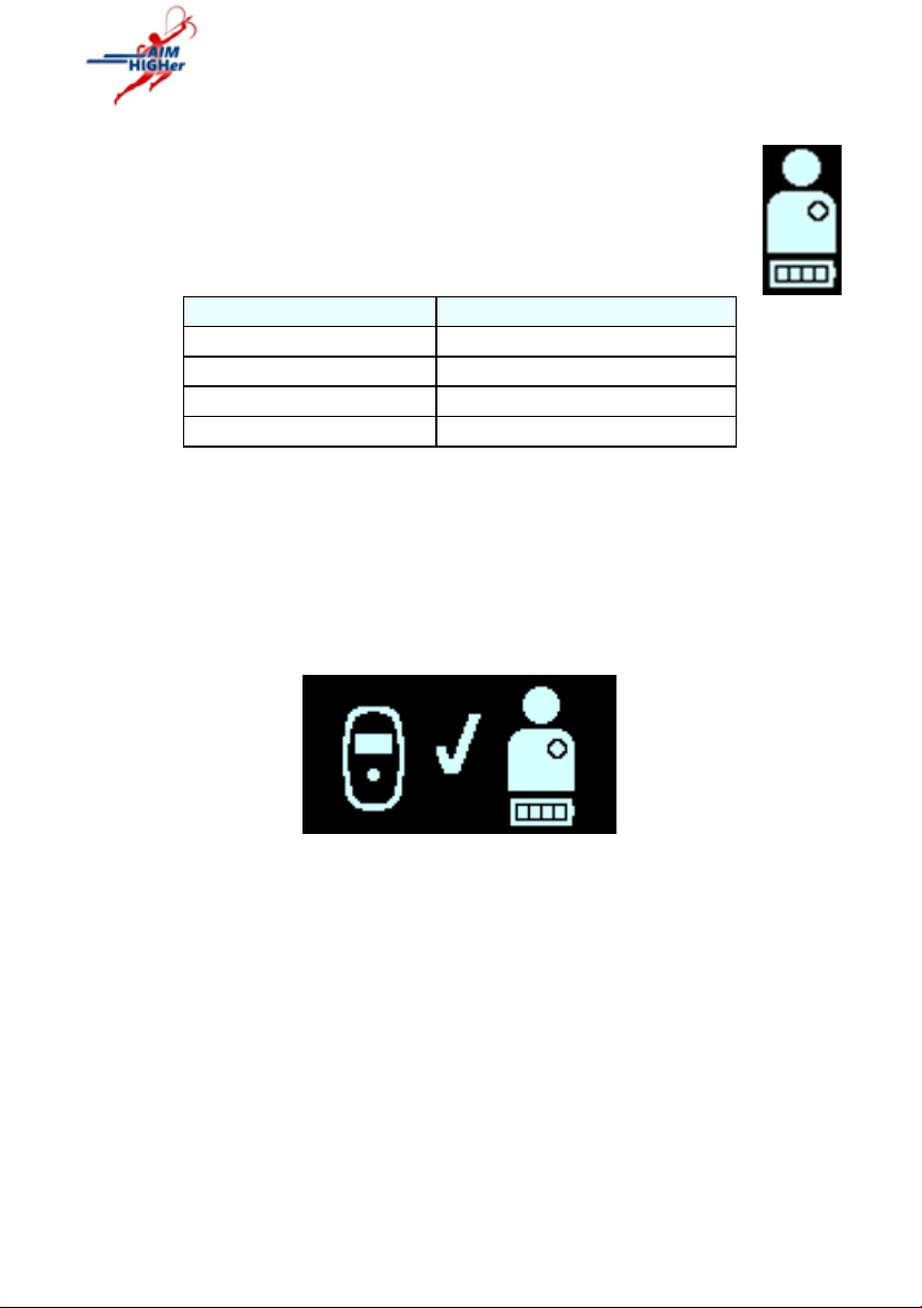
7. The number of bars at the bottom of the Charging IPG
Battery icon (icon image on the right) depicts the current
charge level of the battery in your OPTIMIZER Smart Mini
IPG. See Table 1.
Table 1: OPTIMIZER Smart Mini IPG Battery Charge Levels
IPG Battery Icon
IPG Battery Charge Level
1 flashing bar
Below 25%
2 bars, last one flashing
Between 25% and 50%
3 bars, last one flashing
Between 50% and 75%
4 bars, last one flashing
Above 75%
8. The Charging IPG Status screen will continue to be displayed as your
OPTIMIZER Smart Mini IPG is being charged.
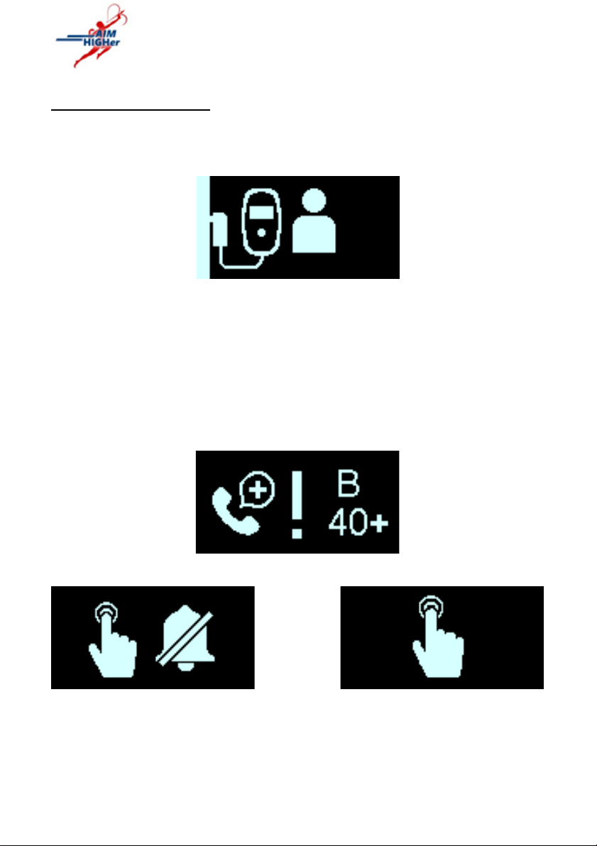
9. When the battery of your OPTIMIZER Smart Mini IPG is fully charged,
the Vesta Charger will emit three short beeping tones and display the
IPG Charging Successfully Completed screen, indicated by the
flashing checkmark in the center of the screen (see Figure 10). The
Vesta Charger will then shut off automatically.
Figure 10: IPG Charging Successfully Completed Screen
10. Detach the charging wand cable clip from your clothing (if necessary),
then remove the Vesta charging wand from your implant site and
undrape the wand cable from around your neck.
11. Reconnect the AC Adapter to your Vesta Charger.

QUICK START GUIDE FOR USING THE
VESTA CHARGER
Impulse Dynamics (USA) Inc. 8 12-250-006-XX, Rev 00
Understanding Alerts
If a Direct Action Alert such as the one shown in Figure 11 is displayed by the
Vesta Charger accompanied by a beeping tone, attempt to charge your
implanted OPTIMIZER Smart Mini IPG using the Vesta Charger.
Figure 11: Long Time Without Downloading Data From IPG Alert Screen
If a Call Doctor Alert Screen, with a flashing exclamation point at the center of
the screen and a Call Doctor Code (preceded by a letter denoting the IPG
model code) such as the one shown in Figure 12 is displayed by the Vesta
Charger, followed by the Snooze Buzzer or Snooze Alert screen (see Figures
13 and 14), take note of the code displayed by your charger and then press
the Power Button on the Vesta Charger to snooze the activated alert.
Afterwards, please call the 24-hour Support Hotline (866-312-5370) and
inform them of the alert code displayed on the Vesta Charger.
Figure 12: Example of Call Doctor Alert Screen
Figure 13: Snooze Buzzer Figure 14: Snooze Alert Screen
Alert Screen
Table of contents