AIMS Power Global LF Series User manual

Global LF Series Pure Sine Wave Inverter Charger
User’s Manual
Version 9.0
PICOGLF10W-PICOGLF60W


1
Table of Contents
1. Important Safety Information..................................................................................................................................... 2
1-1. General Safety Precautions................................................................................................................................. 2
1-2. Precautions When Working with Batteries.......................................................................................................2
2. Introduction................................................................................................................................................................. 3
2‐1. General Information............................................................................................................................................ 3
2-2. Application........................................................................................................................................................... 3
2‐3. MechanicalDrawing.............................................................................................................................................4
2‐4. Features................................................................................................................................................................6
2-5. Electrical Performance.......................................................................................................................................6
3. Installation................................................................................................................................................................. 20
3.1 Unpacking and Inspection.................................................................................................................................20
3‐2.Location.............................................................................................................................................................. 21
3‐3.DCWi
ring........................................................................................................................................................... 21
3‐4.ACWi
ring........................................................................................................................................................... 23
3-5. Grounding..........................................................................................................................................................26
3‐6 Install Flange........................................................................................................................................................27
4. Troubleshooting Guide.............................................................................................................................................. 29
5. Warranty....................................................................................................................................................................31
Specifications.............................................................................................................................................................32
Appendix 1 ‐Circu
it Schematics...............................................................................................................................35
Appendix 2 ‐ InstallationD
iagram............................................................................................................................ 36

2
1. Important Safety Information
NOTE: Before using the inverter, read and save this manual.
1‐1. General Safety Precautions
1-1-1. Do not expose the inverter to rain, snow, spray, bilge or dust. To reduce risk of hazard, do not cover
or obstruct the ventilation openings. Do not install the inverter in a zero-clearance compartment.
Overheating may result. Allow at least 12” of clearance around the inverter for air flow. Make sure that the
air can circulate freely around the unit. A minimum air flow of 145CFM is required.
1-1-2. To avoid risk of fire and electronic shock, make sure that existing wiring is in good electrical
condition and that the wire is not undersized. Do not operate the inverter with damaged or substandard
wiring.
1-1-3. This equipment contains components which may produce arcs and/or sparks. To prevent fire and/or
explosion do not install in compartments containing batteries or flammable materials or in a location which
require ignition protected equipment. This includes any space containing gasoline-powered machinery, fuel
tanks, or joints, fittings, or other connection between components of the fuel system.
See Warranty for instructions for servicing the inverter.
1-1-4. Do not disassemble the Inverter Charger. It contains no user-serviceable parts. Attempting to service
the Inverter Charger yourself may result in electrical shock or fire. Internal capacitors remain charged after
all power is disconnected.
1-1-5. To reduce the risk of electrical shock, disconnect both AC and DC power from the Inverter Charger before
attempting any maintenance or cleaning. Turning off controls will not reduce this risk
CAUTION: Equipment damage
The output side of the inverter’s AC wiring should at no time be connected to public power or a generator.
This condition is far worse than a short circuit. If the unit survives this condition, it will shut down until
corrections are made.
Installation should ensure that the inverter’s AC output is, at no time, connected to its AC input.
1‐2. Precautions When Working with Batteries
1-2-1. If battery acid contacts skin or clothing immediately wash with soap and water. If acid enters eyes
immediately rinse eyes with running cold water and seek immediate medical attention.
1-2-2. Never smoke or allow a sparks or flames near the battery.
1-2-3. Do not drop a metal tool on the battery. The resulting spark or short-circuit on the battery will cause
an explosion.
1-2-4. Remove personal metal items such as rings, bracelets, necklaces, and watches when working with a
battery. A battery produces a short-circuit current high enough to weld any metal objects and will cause a
severe burn.
1-2-5. To reduce the risk of injury, charge only deep-cycle lead acid, lead antimony, lead calcium gel cell,
absorbed mat, LIFEPO4 lithium or NiCad/NiFe type rechargeable batteries. Other types of batteries may
swell or burst causing personal injury and damage.

3
2. Introduction
2-1. General Information
The Global LF Series Pure Sine Wave Inverter Charger product line is a combination of an
inverter, battery charger and auto AC transfer switch in one unit and has a peak conversion
efficiency of 88%. It is packed with unique features and is one of the most advanced inverter
chargers on the market today. It features power factor correction, sophisticated multi-stage
charging and pure sine wave output with unprecedentedly high surge capability to meet
demanding power needs of inductive loads without damaging the equipment.
When utility AC power cuts off (or falls out of acceptable range), the transfer relay is de-energized and the
load is automatically transferred to Inverter mode. Once the qualified AC power is restored the relay is
reenergized and the load is automatically reconnected to AC bypass mode. NOTE THE BYPASS RATING
OF THE INVERTER (page 34) AND DO NOT EXCEED. DAMAGE MAY OCCUR
AND VOID
THE WARRANTY. The Global LF Series Inverter is equipped with a powerful four stage smart charger
and includes an auto generator start feature. The overload capacity of the inverter charger products is 300%
of continuous output for up to 20 seconds to reliably support tools and equipment. This is for inverter
mode only. You can NOT bypass the surge rating of the inverter. This may cause permanent damage to the
inverter.
Another important feature is the "Battery" priority setting via a DIP switch on the back of the inverter charger.
This helps to extract maximum power from the battery in renewable energy systems such as solar and wind.
The Global LF Series Pure Sine Wave Inverter is suitable for renewable energy systems in work trucks, RV,
marine and emergency appliances.
To get the most out of the power inverter, it must be operated and maintained properly. Please read the
instructions in this manual before installing and operating.
2‐2. Application
Power tools–circular saws, drills, grinders, sanders, buffers, weed and hedge trimmers, air compressors.
Office equipment – computers, printers, monitors, facsimile machines, scanners.
Household items – vacuum cleaners, fans, fluorescent and incandescent lights, shavers, sewing machines.
Kitchen appliances – refrigerators, freezers, coffee makers, blenders, ice markers, toasters.
Industrial equipment – metal halide lamp, high pressure sodium lamp.
Home entertainment electronics – television, DVRs, video games, stereos, musical instruments, satellite
equipment.

4
2-3. MechanicalDrawing
1000W-6000W DC Battery Side
1000W & 1500W AC Side and do NOT include a AC terminal block

5
2000W & 3000W AC Side and include outlet and AC terminal block
4000W-6000W AC Side and only include AC terminal block

6
2-4. Features
High overload ability up to 300% of rated power (20 sec
Low quiescent current, low power “Power Saving Mode” to conserve energy
Automatic Generator Start
4-step intelligent battery charger, PFC (Power Factor Correction for charger
8 pre-set battery type selector switch plus de-sulphation for completely flat batteries
Powerful charge rate of up to 115Amp, selectable from 0% 100% (based on model)
10 ms typical transfer time between battery and AC, guarantees power continuity
LCD or LED remote controls (optional
15s delay before transfer when AC resumes, extra protection for loads when used with generator
Allows start up and throughput power with depleted batteries 30A/40A (bypass current)
Multiple controlled cooling fans
Extensive protections against various harsh situations
13VDC battery recovery point, dedicated for renewable energy systems
2‐5. Electrical Performance
2.5.1 Inverter
Topology
The Global LF inverter/charger is built according to the following topology.
Invert: Full Bridge Topology.
Charge: Isolated Boost Topology.
It works bi-directionally: in one direction it converts DC power from the battery to AC power (Inverter
Mode) and in the other direction it converts external AC power to DC power to charge the batteries (AC
Mode). The same power components are used in both directions, resulting in high-energy transfer efficiency
with fewer components.
When operating in inverter mode, the direct current (DC) that enters the inverter from the batteries is filtered
by a large input capacitor and switched "On" and "Off" by the Metal Oxide Silicon Field Effect Transistors
(MOSFET) at a rate of 50 Hz or 60Hz, in this step the DC is converted to low voltage synthesized sine wave
AC using an H-bridge configuration and high frequency PWM (Pulse Width Modulation) technique. It is
then directed into the transformer which steps the low AC voltage up to 230 or 120 volts.
The unit has a 16bit, 4.9MHZ microprocessor to control the output voltage and frequency as the DC input
voltage and/or output load varies.
Because of the high efficiency MOSFETs and the heavy transformers, it outputsPURESINEWAVEAC
with an average THD of 10% (min 3%, max 20% under full linear loads) depending on load connected
and battery voltage. The peak DC to AC conversion efficiency of the Global LF series is >88%.
Don’t parallel the AC output of the inverters to increase power capacity as they have no
stacking functionality.

7
Overload Capacity: The Global LF series inverters have high overload capacities, making it ideal to handle
demanding loads.
1. For 110%<Load<125%(±10%), no audible alarm for 14 minutes, beeps 0.5s every 1s in the 15th minute,
a nd Fault (Turn off) after the 15th minute.
2. For 125%<Load<150%(±10%), beeps 0.5s every 1s and Fault (Turn off) after 1 minute.
3. For 300% ≥Load>150%(±10%), beeps 0.5s every 1s and Fault (Turn off) after 20s.
Caution:
After the inverter is switched on, it takes time for it to self-diagnose and ready to deliver full power. Hence,
always switch on the load(s) after a few seconds of switching on the inverter. Avoid switching on the inverter
with the load already switched on. This may prematurely trigger the overload protection. When a load is
switched on, it may require an initial higher power surge to start. If multiple loads are being powered, they
should be switched on one by one so that the inverter is not overloaded by the higher starting surge if all the
loads are switched on at once.
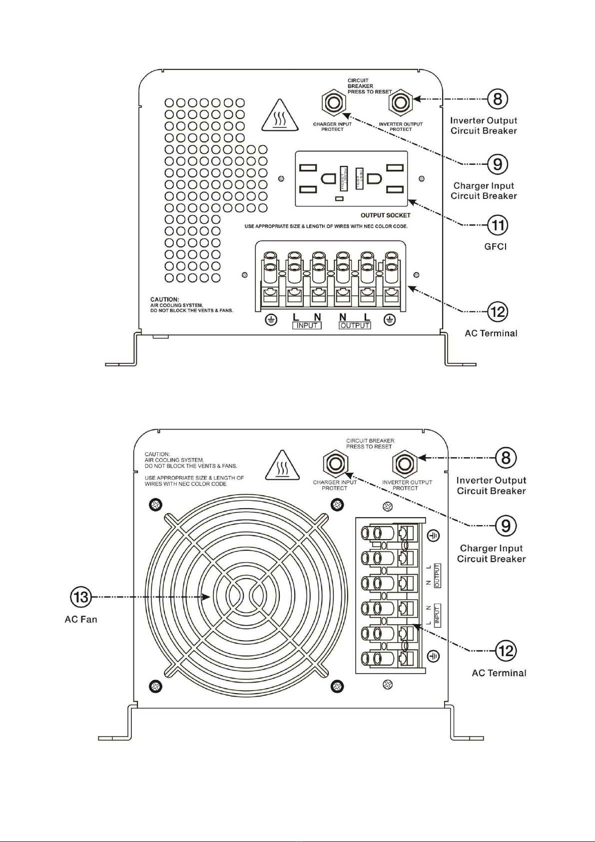
2.5.2 AC Charger
The inverter charger is equipped with an active PFC (Power Factor Corrected) multistage battery charger.
The PFC feature is used to control the amount of power used to charge the batteries in order to obtain a
power factor as close as possible to 1.
Unlike other inverters whose max charging current decreases according to the input AC voltage, the Global
LF series charger is able to output max current as long as the input AC voltage is in the range of 164-
243VAC (95-127VAC for 120V model), and AC frequency is in the range of 48-54Hz (58-64Hz for
60Hz model).
The Global LF series inverter has a very rapid charge current available, and the max charge current can be
adjusted from 15%-100% (based on model) via a liner switch to the right of the battery type selector. This
will be helpful if you are using our powerful charger on a small capacity battery bank. Fortunately, the liner
switch can effectively reduce the max charging current to 15-20% of its peak (based on model). Choosing
“0” on the Battery Type Selector will disable the charging function.
Caution:
Turn the charge current control switch gently to avoid breakage due to over-turning. Not covered
under warranty.
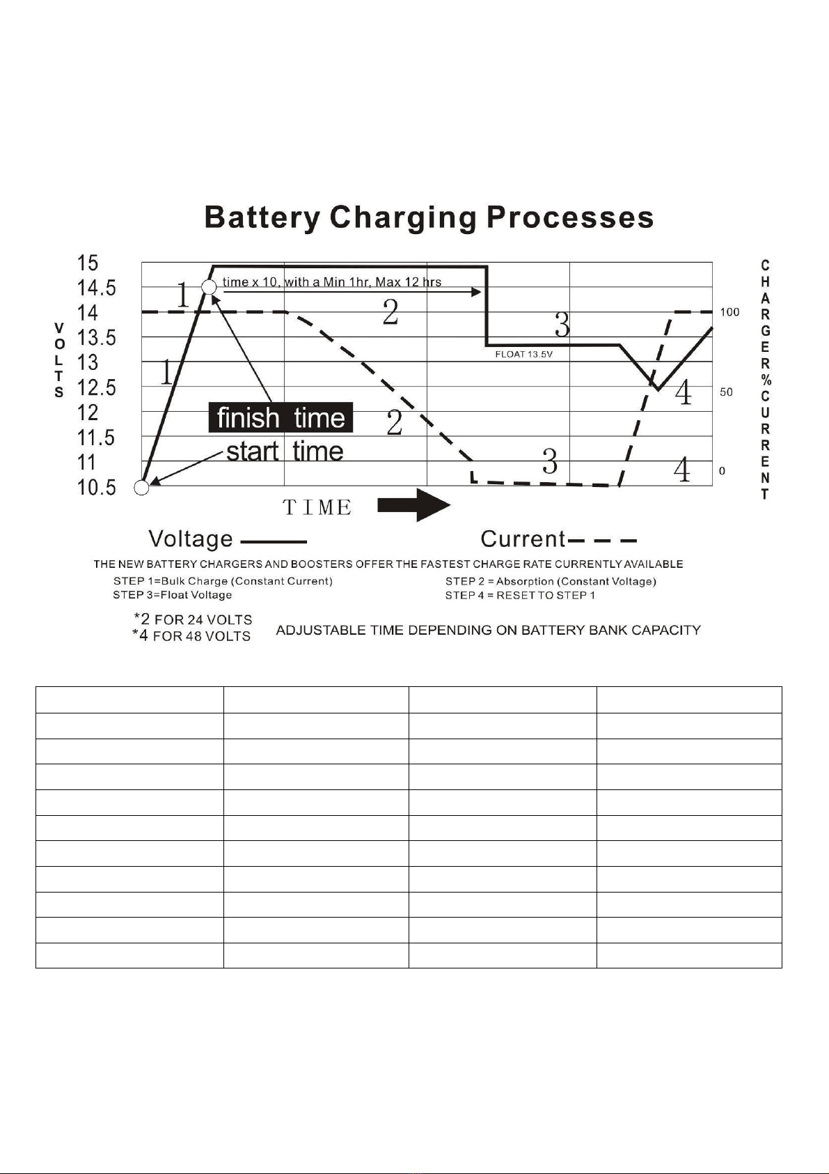
There are 3 charging stages:
Bulk Charging: (fast charge LED solid)this is the initial stage of charging. While Bulk Charging, the
charger supplies the battery with controlled constant current. The charger will remain in Bulk charge until
the Absorption charge voltage (determined by the Battery Type selection) is achieved.
A software timer will measure the time from A/C start until the battery charger reaches 0.3V below the
boost voltage, then take this time asT0 and T0×10 = T1.
Absorb Charging:(fast charge LED blinking)This is the second charging stage when the fast charge LED is
flashing and begins after the absorb voltage has been reached. Absorb Charging provides the batteries with a
constant voltage and reduces the DC charging current in order to maintain the absorb voltage setting. In this
period, the inverter will start a T1 timer; the charger will keep the boost voltage in Boost CV mode until the
T1 timer has run out. Then drop the voltage down to the float voltage. The timer has a minimum time of 1
hour and a maximum time of 12 hours.
Float Charging: (float charge LED solid) The third charging stage occurs at the end of the Absorb
Charging time. While Float charging, the charge voltage is reduced to the float charge voltage

8
(determined by the Battery Type selection*). In this stage, the batteries are kept fully charged and ready if
needed by the inverter.
If the AC is reconnected or the battery voltage drops below 12Vdc/24Vdc, the charger will restart the above
cycle.
If the charge maintains the float state for 10 days, the charger will deliberately reset the cycle to protect the
battery.
Battery Type Selector
Switch setting Description Boost / Vdc Float / Vdc
0 Charger Off
1 Gel USA 14.0 13.7
2 AGM 1 14.1 13.4
3 AGM 2 14.6 13.7
4 Sealed lead acid 14.4 13.6
5 Gel EURO 14.4 13.8
6 Open lead acid 14.8 13.8
7 Lithium battery 14.4 14.4
8 De-sulphation 15.5 (4 Hours then Off)
9 Not used
For 24V X 2, for 48V X 4. (X= multiply)
*Check the required charging specifications with the battery manufacturer. The chart above is just a guide.

9
De-sulphation
The de-sulphation cycle (switch position 8) is a very dangerous setting if you do not know what you are
doing. Before attempting to use this cycle, you must clearly understand what it does and when and how
you would use it.
What causes sulphation? This can occur with infrequent use of the batteries or if the batteries have been
discharged low enough that they will not accept a charge. This cycle is a very high voltage charge cycle
designed to try to break down the sulphated crust that is preventing the plates from taking a charge and
allowing the plates to clean up and accept a charge once again.
Charging depleted batteries
The Global LF series inverter allows a generator to start up and through power (bypass) after batteries
are depleted. See top of page 10 for generator recommendation.
For 12VDC models: after the battery voltage goes below 10V and the power switchiskeptinthe"ON"
position and the inverter stays connected to the battery and the battery voltage doesn’t drop below 9V,
the inverter will be able to charge the battery once qualified AC inputs are present.
Before the battery voltage goes below 9VDC, the charging can be activated when the switch is turned to
“OFF”, then to “ON”.
When the voltage goes below 9VDC, and you accidentally turn the switch to OFF or disconnect the
inverter from the battery, the inverter will not be able to charge the battery once again, because the CPU
loses memory during this process.
For 24VDC models: multiply all VDC by 2.
For 48VDC models: multiply all VDC by 4.
Charging current for each model
The charging capacity will go to peak charge rate in approximately 3 seconds. This may cause a generator to
drop frequency, making the inverter transfer to battery mode. It is recommended to gradually put the
charging load on the generator by switching the charging switch from min to max. Together with the 15s

10
switch delay our inverter gives the generator enough time to spin up. This will depend on the size of the
generator and rate of charge.
Generally, the Bulk Charging Current should be limited to 20% of the capacity of the battery bank. Higher
charging current may be used if permitted by the battery manufacturer.
Warning: Items of note not covered under warranty.
To set the charge current control switch, use a small jeweler’s style flat-head screwdriver and gently turn to
avoid breakage due to over‐turning.
To guarantee the best performance of the built in AC charger, when the AC input is from a generator,
the standby generator should be of a least 50% higher capacity than the inverter. Example, if you are
using a 2000 watt inverter, the generator must be 3000 watt or larger. If using a 3000 watt inverter, the
generator must be 4500 watt or larger, an so on. If operating with an under-rated generator with
unqualified wave form may cause premature failure and is not covered under warranty.
2.5.3 Transfer
Swift Power Transfer
While in Standby Mode, the AC input of the inverter is continually monitored. Whenever AC power falls
below the low AC voltage trip voltage (90VAC default setting for 120VAC), the inverter automatically
transfers back to the Invert Mode with minimum power interruption to your appliances – as long as the
inverter is turned on. The transfer from Standby Mode to Inverter Mode occurs in approximately 10
milliseconds. It is the same from Inverter Mode to Standby Mode. This transfer time is usually fast enough
to keep your equipment power up, thus our inverter can be used as a line interactive UPS.
Synchronized Power Transfer
When a load is transferred from inverter AC output to another backup AC source of power through the transfer
switch, there will be a finite interruption of power to the load for transfer to take place. A mismatch of phase
and frequency of the inverter AC output and the backup AC source in transfer is likely to damage the backup
AC source / a reactive load. With sophisticated circuitry design, our inverter will first lock on the frequency
and phase of the input shore power/generator power and make a smooth and safe transfer at the zero voltage
point of minimize the impact on the power modules.
Transfer Delay
There is a 15 second delay rom the time the inverter senses a continuously qualified AC is present at the input
terminals to when the transfer is made. This delay is built-in to provide sufficient time for a generator to spin-
up to a stable voltage and frequency and avoid relay chattering. The inverter will not transfer to generator until
it has locked onto the generator’s output. This delay is also designed to avoid frequent switch when input
utility is unstable.
2.5.4 Auto Frequency Adjust
The factory default configuration for inverters sold in the American market is 60Hz. If the output frequency
needs to be changed, this is done by putting in a valid input Power Source to the inverter’s input lines. Once
the inverter validates the input, the output will automatically change. NOTE: The inverter will oupt factory set
frequency of 60Hz controlled with DIP switch #4.
2.5.5 Power Saver
There are 2 different working statuses for the Global LF inverters:
“Power On” and “Power Off”.
When the power switch is in “Unit Off” position, the inverter is powered off.

11
When the power switch is turned to either “Power Save ON” or “Power ON”, the inverter is powered on.
The Power Saver function is designed to conserve battery power when AC power is not or rarely required
by the loads.
In this mode, the inverter pulses the AC output looking for an AC load (IE. electrical device). Whenever
an AC load (greater than 50-100 watts depending on model) is turned on, the inverter recognizes the need
for power and automatically starts inverting and output goes to full voltage. When there is no load (or less
than 50-100 watts depending on model) detected, the inverter automatically goes back into search mode to
minimize energy consumption from the battery bank.
In “Power saver on” mode, the inverter will draw power mainly in sensing moments, thus the idle
consumption is significantly reduced. The inverter will detect a load for 250ms every 3 seconds (DOP
switch#3 position 1).
Note: The minimum power of a load to take inverter out of sleep mode (Power Saver On) is 50 Watts for
inverters 1000-3000 watts and 100 Watts for 4000-6000 watts. The Global LF Series is designed with
extremely low idle power consumption, only a mere 0.8-1.8% of its rated power.

12
Global LF Series Idle Power Consumption (in Watts)
Model NO Power Saver Off Power Saver On (3Secs)
PICOGLF10W12V120VR 12.5 7.5
PICOGLF15W12V120VR 13.5 8
PICOGLF20W12V120VR 28 12.7
PICOGLF20W24V120VR 26.5 12.2
PICOGLF20W48V120VR 28 12.7
PICOGLF30W12V120VR 55 21.7
PICOGLF30W24V120VR 46.5 18.9
PICOGLF40W12V120V 44.5 18.2
PICOGLF40W12V240VS 48 19.4
PICOGLF4012120240VS 48 19.4
PICOGLF40W24V120V 52.5 20.9
PICOGLF40W48V240VS 48 19.4
PICOGLF60W24V240V 76.8 29
PICOGLF60W48V120V 82 30
PICOGLF60W48V240V 80.7 30.3
When in the search sense mode, the green power LED will blink, and the inverter will make a
ticking sound.
At full output voltage, the green power LED will light steadily, and the inverter will make a steady
humming sound. When the inverter is used as an “uninterruptible” power supply the search sense mode or
“Power Saver On” function should be defeated.
Exceptions
Some devices when scanned by the load sensor cannot be detected. Small fluorescent lights and inductive
loads are the most common example. (Try altering the plug polarity by turning the plug over.) Some
computers and sophisticated electronics have power supplies that do not present a load until line voltage is
available. When this occurs, each unit waits for the other to begin. To drive these loads either a small
companion load must be used to bring the inverter out of its search mode, or the inverter may be
programmed to remain at full output voltage (Power On mode).
2.5.6 Protections
AC input over voltage protection/AC input low voltage protection
Low battery alarm/high battery alarm
Over temperature protection/overload protection
Short circuit protection (1s after fault)
Back feeding protection
When over temperature /overload occur, after the fault is cleared, the master switch needs to be reset
to restart the inverter.

13
The low battery voltage trip point can be customized from a defaulted value of 10VDC to 10.5VDC thru
SW1 on the DIP switch.
The inverter will go to over temp protection when the heat sink temp. ≥105ºC(221℉), and go to fault
( shutdown Output) after 30 seconds. The switch needs be reset to activate the inverter.
The Global LF series inverter has back feeding protection which avoids presenting an AC voltage on the AC
input terminal in inverter mode.
When a fault is cleared, the inverter will need to be reset to start working.
*We don't recommend connecting AC input to a GFCI circuit as it will cause the supply GCFI to pop
intermittently and fail to supply power to the charger and bypass power through inverter.
2.5.7 Remote Control
In addition to the switch panel on the front (or top) of the inverter, there are two optional remotes, for some
models. An LCD remote panel that provides more detailed info or an LED remote that provides on/off with
a few LED indicators. The LCD remote panel connects to the RJ45 port on the DC side of the inverter
displays several statuses of the inverter (sold separately Part # REMOTELF). Use with port labeled LCD
remote. If you want a simple on/off remote, consider the LED remote (sold separately Part #
REMOTELFLED). Use with port labeled LED remote. Not available on all models.
If an extra switch panel is connected to the inverter via “remote control port”, together with the panel on the
inverter case, the two panels will be connected and operated in parallel.
Whichever first switches from “Off” to “Power saver off” or “Power saver on”, it will power the inverter on.
If the commands from the two panels conflict, the inverter will operate according to the following priority:
Power saver on> Power saver off> Power off
Only when both panels are turned to the “Unit Off” position, will the inverter be powered off.
The max length of the cable is 60 feet.
Remote LED - REMOTELFLED
The remote LED has on/off and power save switch.
There are also 3 indicator LEDs for the battery charger,
inverter mode and faults.
Remote LCD - REMOTELF
The remote LCD displays detailed information of the inverter.

14
(1) Shore/ Generator voltage (6) Output voltage
(2) DC voltage on inverter (7) Output frequency
(3) Load when inverting (8) Bypass/ inverter mode
(4) Low/high voltage, over temp,
overload (9) Battery state of charge graph
(5) Fault condition NOTE: The battery icon is just an image and does not
represent battery capacity. The bar graph will change
based on battery voltage (2). If using lithium, you may
see an instant drop on the graph.
A push button on the left side of the panel
can be used to turn off the LCD screen and
save 0.1A current draw on the battery.
1
2
3
4
5
6
7
8
9
LCD DISPLAY
WARNING
ONLY USE REMOTELF WITH PORT LABELED LCD. ONLY USE REMOTELFLED WITH PORT
LABELED LED. IF YOU PLUG INTO THE WRONG PORT, YOU CAN FRY THE INVERTER AND
NOT COVERED UNDER WARRANTY.
Never cut the remote cable when the cable is attached to inverter and battery is connected to the inverter. Even
if the inverter is turned off, it will damage the remote PCB inside if the cable is short circuited during cutting.

15
2.5.8 LED Indicator Lights/Status

16
2.5.9 Audible Alarm
Battery Voltage Low Inverter green LED lit, and the buzzer beeps 0.5s every 5s.
Battery Voltage High Inverter green LED lit, and the buzzer beeps 0.5s every 1s and Fault after
60s.
Invert Mode Overload
(1)110%<load<125%(±10%), No audible alarm in 14 minutes,
Beeps 0.5s every 1s in 15th minute and Fault after 15 minutes;
(2)125% <load<150%(±10%), Beeps 0.5s every 1s and Fault after 60s;
(3)Load>150%(±10%), Beeps 0.5s every 1s and Fault after 20s;
Over Temperature Heat sink temp. ≥105ºC(221℉), Over temp red LED Lighting, beeps 0.5s
every 1s;
2.5.10 Fan Operation
For 1-3KW models, there is one multiple controlled DC fan which starts to work according to the
below logic.
For 4-6KW models, there is one multiple controlled DC fan and one AC fan. The DC fan will work in
the same way as the 1-3KW models, while the AC fan will work once there is AC output from the
inverter. When the inverter is in power saver mode, the AC fan will work from time to time in response
to the pulse sent by the inverter in power saver mode.
The Operation of the DC fan at the DC terminal side is controlled by the following logic:

17
Condition Enter Condition Leave condition Speed
HEAT SINK T ≤ 140℉ T > 149℉ OFF
TEMPERATURE 149℉≤ T < 185℉ T ≤ 140℉ or T ≥ 185℉ 50%
T > 185℉ T ≤ 176℉ 100%
CHARGER
CURRENT
I ≤ 15% I ≥ 20% OFF
20%< I ≤ 50%Max I≤ 15% or I > 50%Max 50%
I > 50%Max I ≤ 40%Max 100%
LOAD Percentage
(INV MODE)
Load < 30% Load ≥ 30% OFF
30% ≤ Load < 50% Load ≤ 20% or Load ≥ 50% 50%
Load ≥ 50% Load ≤ 40% 100%
Allow at least 12 inches of clearance around the inverter for air flow. Make sure that the air can circulate
freely around the unit.
Fan noise level <60db at a distance of 3 feet
2.5.11 DIP Switches
On the DC end of inverter, there are 5 DIP switches that enable users to customize some of the inverter
charger's functions.
Switch NO Switch Function Position: 0 Position: 1
SW1(Utility Priority)
Low Battery Trip Point
10.0VDC 10.5VDC
SW1(Battery Priority) 10.5VDC 11.5VDC
SW2(230V) AC Input Range 184-253VAC 154-264VAC(40-70Hz)
SW2(120V) AC Input Range 100-135VAC 90-135VAC(40-70Hz)
SW3 Power Save Override Inverter Off Saver On 3 sec
SW4 Frequency Switch 50Hz 60Hz
SW5 Battery/AC Priority AC Priority Battery Priority
Low Battery Trip Volt (SW1)
Deep discharge of the lead acid battery will cause losses in capacity and early aging. In some applications a
different low voltage disconnection level may be preferred. For example, in solar applications, users may
intend to have less DOD to prolong the battery life cycle. While for mobile applications, users may intend to
have more DOD to fully use the battery capacity available, minimizing on- board weight.
For 12VDC models, the Low Battery Trip Volt is set at 10.0VDC by default. It can be customized to
10.5VDC using SW1. This is to prevent batteries from over-discharging while there is only a small load
applied on the inverter.
multiply*2 for 24VDC, multiply*4 for 48VDC
AC Input Range (SW2)
There are different acceptable AC input ranges for different kinds of loads.
For some relatively sensitive electronic devices, a narrow input range of 184-253VAC (100-135V for
120VAC model) is required to protect them.
While for some resistive loads that work in a wide voltage range, the input AC range can be customized to
154-264VAC (90-135V for 120VAC model). This helps to power loads with the most AC input power
without frequently switching to the battery bank.

18
In order to make the inverter accept dirty power from a generator, put SW2 to position “1”, the inverter will
bypass an AC input with a wider voltage and frequency (40-70Hz for 50Hz/60Hz). The AC charger will
also work in a wider voltage and frequency range (42-68Hz for 50Hz/60Hz).
As mentioned, this will avoid frequent switching between battery and generator, but the low-quality power
may affect some sensitive loads. The pros and cons should be considered when dealing with sensitive loads.
NOTE: This is for bypass only! The charger has a different voltage range and may not operate at full rated
current. Refer to Section 2.5.2 AC Charger.
Power Saver Override ON/OFF (SW3)
The factory default for SW3 is Position 0. Position 1 will allow the Power Save feature of the inverter to
detect a load for 250ms every 3 seconds. If a load is detected, the inverter will output AC Power. If SW3 is
moved to Position 0. This will prevent the sense pulse from being sent out, even if inverter is in Power Save
mode via Main Power switch. No power will be output unless Shore Power input is present. Only then will
the battery charger and AC throughput operate when SW3 is in Position 0.
Frequency Switch (SW4):
The output frequency of the inverter can be set at either 50Hz or 60Hz by SW4. 50Hz most common in
Europe and Africa.
AC/Battery Priority (SW5):
The inverter charger is designed with AC priority as default. This means, when AC input is present, the
battery will charge first, and the inverter will transfer the input AC to power the load. Only when the AC
input is stable for a continuous period of 15 days will the inverter start a battery inverting cycle to protect
the battery. After 1 normal charging cycle AC throughput will be restored.
The AC Priority and Battery Priority switch is SW5. When you choose battery priority, the inverter will
invert from battery first and then AC input when battery voltage drops. Only when the battery voltage
reaches the low voltage alarm point (10.5V for 12V,21Vdc for 24Vdc, 42Vdc for 48Vdc) will the inverter
transfer to AC Input, charge battery, and switch back to battery when the battery is fully charged. This
function is most common for wind/solar systems using utility power as back up.
Note: In battery priority mode, when qualified AC inputs for the first time and the battery voltage is below 12.5Vdc (12.5Vdc for
12Vdc, 25Vdc for 24Vdc, 51Vdc for 48Vdc, the inverter will go into battery priority mode only after a cycle of bulk charging and
absorb charging is finished. The inverter will not go into float charging mode.
2.5.12 Auto Generator Start
BEFORE YOU USE A GENERATOR, MAKE SURE IT IS SIZED TO HANDLE THE INVERTER.
To guarantee the best performance of the built in AC charger and when the AC input is from a generator,
the standby generator should be at least 150% higher capacity than the inverter.
Operating with an under-rated generator or generator with unqualified wave form may cause premature
failure which is not covered under warranty. Example: If you are using a 2000 watt inverter charger, your
generator must be 3000 watts or larger. If you are using a 3000 watt inverter charger, your generator must be
4500 watt or larger, and so on.
The inverter is able to start up a generator when battery voltage drops. When the inverter goes into low
battery alarm, it can send a signal to start a generator and turn the generator off after battery charging is
completed. The auto gen start feature will only work with generators that have an automatic starting
function. The generator must have start and stop controls [an electric starter and electric choke (for gasoline
units)], and the safety sensors to be able to start and stop automatically. There is an open/close relay that
will short circuit the positive and negative cables from a generator start control. The input DC voltage can
vary, but the max current the relay can carry is 16 amps. The Auto Gen Start terminal pins are not polarized.
These two pins can also be used as dry contacts to send out “Low Battery Voltage” signal to an external
alarm device. Use 18 AWG speaker wire for this application.
Other manuals for Global LF Series
2
This manual suits for next models
15
Table of contents
Other AIMS Power Batteries Charger manuals