AIMS Power CON120AC12/24VDC User manual

AC CONVERTER / BATTERY CHARGER
User’s Manual
MODEL #: CON120AC12/24VDC
Listed to UL 458 and CSA 22.2 NO. 107.1
Standards

Contents
INTRODUCTION..................................................................................................................................................... 3
Important Safety Instructions................................................................................................................................. 3
1. General Description.................................................................................................................................... 5
1.1 Features..................................................................................................................................................... 5
2. Installation and Operation................................................................................................................................. 6
2.1 Front Panel Description........................................................................................................................... 6
2.2 Rear Panel Description............................................................................................................................ 7
2.3 DC Output Battery Connection............................................................................................................... 8
2.4 AC Input Connection................................................................................................................................ 9
2.5 Parallel Connection.................................................................................................................................. 9
3. Troubleshooting.................................................................................................................................................. 9
4. Specifications.................................................................................................................................................... 10

MATRIX Inverter System User Manual
- 3 -
I
IN
NT
TR
RO
OD
DU
UC
CT
TI
IO
ON
N
You have purchased the AIMS Power 12V/24V AC Converter and Battery Charger. This product will
bring you reliable power when used and maintained properly. This manual provides safety guidelines,
detailed planning and setup information, installation procedures, as well as information about operating
and troubleshooting the unit. This manual does not provide details about specific brands of batteries.
AIMS Power recommends you consult the battery manufacturer for charging information.
READ THE MANUAL AND UNDERSTAND ALL SAFETY PRECAUTIONS BEFORE INSTALLING AND
OPERATING THE UNIT. SAVE THE MANUAL FOR FUTURE REFERENCE.
I
Im
mp
po
or
rt
ta
an
nt
t
S
Sa
af
fe
et
ty
y
I
In
ns
st
tr
ru
uc
ct
ti
io
on
ns
s
CAUTION
1. Installation and service should be performed by a qualified service technician. High voltage is present
inside unit. Incorrect installation or use may result in risk of electric shock or fire. No user serviceable
parts inside the unit.
2. Remove all sources of power, utility and battery power before servicing or installing.
3. Risk of explosive gases
Working near batteries is dangerous. Batteries produce explosive gases during normal
battery operation.
To reduce risk of battery explosion, follow the instructions in this manual and the
instructions from the battery manufacturer.
4. Plan ahead
Someone should be within range of your voice or close enough to come to your aid when
working near a lead-acid battery.
Have plenty of fresh water and soap nearby in case battery acid contacts skin, clothing or

MATRIX Inverter System User Manual
- 4 -
eyes.
Wear complete eye protection and clothing protection.Avoid touching eyes while working
near battery.
If battery acid contacts skin or clothing, wash immediately with soap and water. If acid
enters eye, immediately flood eye with running cold water for at least 10 minutes and get
medical attention immediately.
NEVER smoke or allow a spark or flame in vicinity of battery.
Be extra cautious to reduce risk of dropping metal tool onto battery. It might spark or short
circuit battery or other electrical part that may cause explosion.
Remove personal metal items such as rings, bracelets, necklaces, and watches when
working with a lead-acid battery. A lead-acid battery can produce a short circuit current
high enough to weld a ring or like metal, causing a severe burn.
5. Preparing to charge
Never charge a frozen battery.
Be sure battery is mounted in a well-ventilated compartment.
Add distilled water in each cell until battery acid reaches level specified by battery
manufacturer. This helps purge excessive gas from the cells. Do not overfill. For a battery
without cell caps, carefully follow manufacturers charging instructions. (only for flooded
batteries)
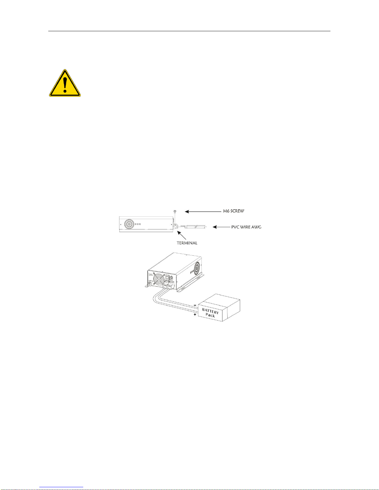
6. Charger location & installation
In an event of failure, the unit could produce arcs or sparks. NEVER install in battery or
engine compartment or in the presence of explosive gases. Keep all gases away from unit.
Protect all wiring from physical damage, vibration and excessive heat.
Insure that the unit is properly setup for the type of battery being charged.
Do not expose unit to rain or snow.
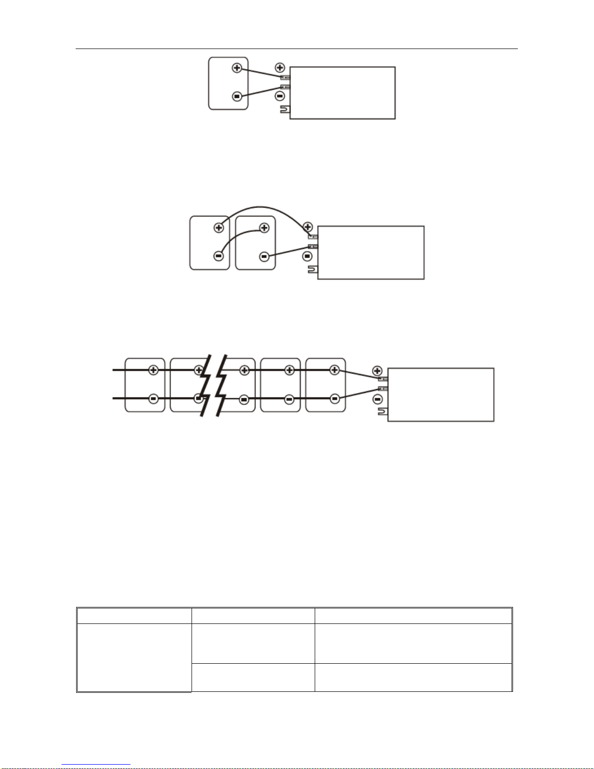
Insure all terminating connections are clean and tight to prevent arcing and overheating.
Unit must be properly installed as described in these instructions prior to operation.
Do not adjust any functions including the current, voltage and battery type when unit is
working. All adjustments must be made when converter is disconnected.

MATRIX Inverter System User Manual
- 5 -
1
1.
.
G
Ge
en
ne
er
ra
al
l
D
De
es
sc
cr
ri
ip
pt
ti
io
on
n
The AIMS PowerAC Converter / Battery Charger 12V/24V is ideal for applications that require diverse
ways of recharging batteries. There are many ways to recharge batteries and the wideAC input range of
this unit accommodates most applications and battery technologies. Useful with generators and shore
power, this converter charges various types of batteries such as, open lead acid,AGM, Gel and LiFePO4.
The reliable high frequency structure, accepts wide range input voltages of 70Vac to 145Vac to
accommodate unstable inputs. The unit also includes a selectable 12Vdc or 24Vdc output. The AIMS
PowerAC Converter / Battery Charger provides the flexibility for almost any application and the large
charging capacity of 75 amps gets the job done quickly.
1
1.
.1
1
F
Fe
ea
at
tu
ur
re
es
s
Three stage variable charging voltage algorithm for maximizing the battery lifetime. Bulk,
absorb and float
Large charging capacity design (75Amp for 12Vdc; 37.5 Amp for 24Vdc) less charging
time needed
Adjustable charge current control setting is based on connected battery’s capacity to safely
charge batteries and avoid over charging.
Wide input voltage range, 70Vac to 145Vac for unstable input
High AC to DC converting efficiency design (higher than 80%)
Smart fan control for maximizing the performance and fan life
Includes battery temperature sensor port to help maintain the life of the battery(s)

MATRIX Inverter System User Manual
- 6 -
2
2.
.
I
In
ns
st
ta
al
ll
la
at
ti
io
on
n
a
an
nd
d
O
Op
pe
er
ra
at
ti
io
on
n
2
2.
.1
1
F
Fr
ro
on
nt
t
P
Pa
an
ne
el
l
D
De
es
sc
cr
ri
ip
pt
ti
io
on
n
Figure 1 Front Panel
Main Switch
ON:Once CSB10L1224 has been properly installed and batteries are connected,flip the switch to
“ON”, CSB10 L1224 will turn on automatically, and works according to the input AC source’s
status.
OFF:Flip the switch to “OFF”, CSB10L1224 will turn off.
BTS Port
Connect the BTS to this port.
A battery temperature sensor (BTS) can be used to ensure proper charging of the batteries based on
temperature. Installing a BTS extends battery life by preventing overcharging in warm temperatures and
undercharging in cold temperatures.
Ground Terminal
Connect the GND to the Ground Terminal using 8AWG wire.
Battery Connector
Connect the Battery to the Positive (+) Battery Terminal and the Negative (-) Battery Terminal. Do NOT
reverse the polarity!

MATRIX Inverter System User Manual
- 7 -
2
2.
.2
2
R
Re
ea
ar
r
P
Pa
an
ne
el
l
D
De
es
sc
cr
ri
ip
pt
ti
io
on
n
Figure 2 Rear Panel
LED Indicator
The unit has green, yellow and red LEDs to indicate the operating status of theAC converter.
Table 1 –1: LED status indicator
Conditions
Red(Fault RED)
Yellow(Status YEL)
Green(Status GRN)
Mode select fault
Blinking 0.5s
Blinking 0.5s
Blinking 0.5s
Output voltage too low
Solid
Blinking 2s
Off
Fan fault
Blinking 0.5s
Off
Off
Over temperature
Blinking 2s
Off
Off
Output over voltage
Solid
Blinking 0.5s
Off
Output over current
Solid
Solid
Off
Input over / Under voltage
/Frequency
Solid
Off
Off
Constant current / Constant Voltage
Off
Solid
Solid
Float stage
Off
Blinking 2s
Solid
Battery over temperature
Off
Blinking 2s
Off
Battery Type Select
The AC Converter can charge four types of batteries, which can be set using the dial switch
Table 1 –2: Battery Type
Battery type
SW1
SW2
Open lead acid
0
1
Gel
1
0
AGM
1
1
LiFePo4
0
0
Charge Current Control Dial
This dial can adjust the amount of charge current. The adjustment range is 20%-100% of the total
current rating.

MATRIX Inverter System User Manual
- 8 -
Input terminal
The unit can accept input voltages ranging from 70Vac –145Vac.
CAUTION Before connecting, power off the unit and make sure theAC cord is not
plugged into an AC outlet.
2
2.
.3
3
D
DC
C
O
Ou
ut
tp
pu
ut
t
B
Ba
at
tt
te
er
ry
y
C
Co
on
nn
ne
ec
ct
ti
io
on
n
–
–B
Ba
at
tt
te
er
ry
y
s
sh
ho
ou
ul
ld
d
b
be
e
c
co
on
nn
ne
ec
ct
te
ed
d
f
fi
ir
rs
st
t
t
th
he
en
n
A
AC
C
p
po
ow
we
er
r
c
ca
an
n
b
be
e
a
ap
pp
pl
li
ie
ed
d.
.
U
Us
se
e
i
in
nc
cl
lu
ud
de
ed
d
A
AC
C
c
ca
ab
bl
le
e
c
co
on
nn
ne
ec
ct
te
ed
d
t
to
o
a
a
m
mi
in
ni
im
mu
um
m
o
of
f
1
10
0A
A
b
br
re
ea
ak
ke
er
r.
.
Step 1- Follow battery polarity guide located near battery terminal! Place the battery cable ring terminal
over AC Converter / Battery Charger’s battery terminal. Tighten the M6*12 Screw. Do not place anything
between the flat part of battery terminal and the battery cable ring terminal, or overheating may occur.
Figure 1: Battery to Charger cable connection
Caution! DO NOT place anything between battery cable ring terminals and battery terminals. The
terminal stud is not designed to carry current. Apply anti-oxidant paste to terminals after terminals have
been torqued.
Step 2- Connect battery cables to your batteries
1) Single battery connection: When using a single battery, its voltage must be equal to the voltage of
unit’s nominal input voltage.
Figure 2: Single battery connection

MATRIX Inverter System User Manual
- 9 -
2) Series battery connection: When using multiple batteries in series, all batteries must equal in voltage
and amp hour capacity, and the sum of their voltages must be equal to the voltage of unit’s nominal input
voltage.
Figure 3: Series battery connection
3) Parallel battery connection: When using multiple batteries in parallel, each battery’s voltage must be
equal to the voltage of unit’s nominal input voltage.
Figure 4: Parallel battery connection
2
2.
.4
4
A
AC
C
I
In
np
pu
ut
t
C
Co
on
nn
ne
ec
ct
ti
io
on
n
Use providedAC cable. Connect to a breaker minimum of 10A. AC voltage range of 70Vac to 145Vac.
2
2.
.5
5
P
Pa
ar
ra
al
ll
le
el
l
C
Co
on
nn
ne
ec
ct
ti
io
on
n
To get more charge current, the Battery Charger can be connected in parallel configuration. Maximum of
two units can be connected in parallel. For example, in 12Vdc mode, connecting 2 Battery Chargers in
parallel can get maximal 150Amp charging current. In 24Vdc mode, the paralleled system can reach
maximal 75Amp current.
3
3.
.
T
Tr
ro
ou
ub
bl
le
es
sh
ho
oo
ot
ti
in
ng
g
Table 1 –3: Troubleshooting list
Symptom
Probable cause
Items to examine or correct
Completely dead, no
display
No battery power
Battery disconnected, over discharged, or
connected in reverse, no display polarity.
Battery voltage too low
Battery voltage must be at least 10V for the
unit to operate.

MATRIX Inverter System User Manual
- 10 -
Power switch is not on
Press and hold power switch.
AC power present at
distribution panel
AC input is missing
Check AC input connections.
Breaker has popped
Reset the input protector.
Green, yellow and red
LED blinking 0.5s
together
Mode select fault
12V mode:Adjust battery voltage lower than
15V
24V mode: Adjust battery voltage higher
than 18V
Red LED blinking 0.5s
other LEDs off
Fan fault
Check the fan in charger
Red LED Blinking 2s
The charger is operating
over temperature
On the heat sink of DC-DC part should be
operate below 105°C
If any other situations occur that are not listed above, call service technician immediately.
4
4.
.
S
Sp
pe
ec
ci
if
fi
ic
ca
at
ti
io
on
ns
s
4
4.
.1
1
I
In
np
pu
ut
t
Input Voltage
96-145VAC full performance
70-96VAC automatically de-rate to 50% of full load current
Frequency
40Hz to 70Hz
Nominal Input Current at Rated
Output
<9Aac
Voltage Measurement Accuracy
±8Vac
Frequency Measurement Accuracy
±1Hz
4
4.
.2
2
O
Ou
ut
tp
pu
ut
t
Nominal Voltage
12/24Vdc manual adjustable
Output Current
Input voltage 96-145V,
output current 75A for 12V mode
output current 37.5A for 24V mode
Input voltage 70-96V,
output current 37.5A for 12V mode
output current 18.75A for 24V mode
Rated Output Current
Manual adjustable
Current Accuracy
± 6% of full rated output current @25°C, for target currents
across the range from 10% rated output (for absorption exit
criteria accuracy) to the current limit setpoint.
Load Regulation
1.5%
Current Limit
75-80Amp
Dead-Battery Charging
8-14.9Vdc at 100% of rated output current
8-29.8Vdc at 100% of rated output current
Selectable Battery Type
Open Lead-Acid, Gel, AGM, LiFePo4, adjustable
Parallel Outputs
Maximum of two AC converter units connected in parallel
Efficiency
80%

MATRIX Inverter System User Manual
- 11 -
4
4.
.3
3
P
Pr
ro
ot
te
ec
ct
ti
io
on
n
Input Over Voltage
Unit must be safe for input voltage up to 150VacRMS (and up
to 215Vpeak), need not be operating.Above this level the unit
may be damaged.
Reverse Battery Polarity Protection
Non-destructive reverse battery polarity protection with fuses.
Unit shall not sustain damage and shall meet all specifications
after fuse replacement.
Input Under-voltage
Unit must not be damaged for all input voltages from
0-300Vac. Shutdown or input current limit or other means may
be applied when input voltage is out of normal operating
range.
Output over voltage
12/24V mode
12Vdc. Unit will shut down if Vcharging > Vcharging (target) +
1.0Vdc for more than 2 seconds; unit will restart when voltage
<= Vcharging (target) for more than 2 seconds.
For battery OVP the unit will restart in the same stage.
24Vdc. Unit will shut down if Vcharging > Vcharging (target) +
1.5Vdc for more than 2 seconds; unit will restart when voltage
<= Vcharging (target) for more than 2 seconds.
For battery OVP the unit will restart in the same stage.
Charger over temperature
protection
The internal temperatures of the charger will be measured by
NTC. Based on these measurements, unit will shut down if the
temperature exceeds 105°C. Unit will restart when
environment temperature cools to 95 °C.
BTS(Battery Temperature Sensing)
The battery temperature sensor allows the charge controller to
continuously adjust charge voltage / charge current based on
actual battery temperature.
When the battery temperature is over 40 °C, unit will reduce
the charging voltage to Float voltage, also it will reduce the
Max charging current by 10% with every two degree of
temperature rise.
When the battery temperature is over 50 °C, unit will shut
down.
4
4.
.4
4
E
En
nv
vi
ir
ro
on
nm
me
en
nt
ta
al
l
Operation temperature
Nominal ambient temperature: 25°C
Operating Ambient Temperature range: -10°C to 40°C
(On the heat sink of DC-DC part, if the temperature is over
90 ℃, the Charger Current will be de-rate to 50% ; if the
temperature is over 105 ℃, the Unit will be shut down.)
Relative humidity
5~95% without condensation
Noise
Unit requirements: below 50dB (A) measured at 1 m
distance with fan full working.
Storage Conditions Temperature
-20°C to +80°C
Cooling
Smart fan control
Safety
UL458,CSA22.2#107.1
4
4.
.5
5
M
Me
ec
ch
ha
an
ni
ic
ca
al
l
Dimension (D x W x H) mm
10.25” * 6.75” * 3.25”
Unit Weight
6.5 lb
Gross Weight
7 lb
Table of contents
Other AIMS Power Batteries Charger manuals