AimTTi QPX750SP User manual

INSTRUCTION MANUAL
EN
INSTRUCTION MANUAL
QPX750SP
750W Laboratory Power Supply

CONTENTS
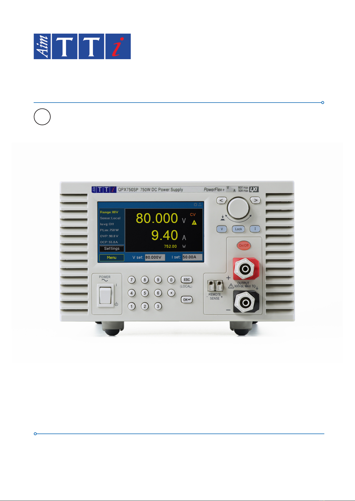
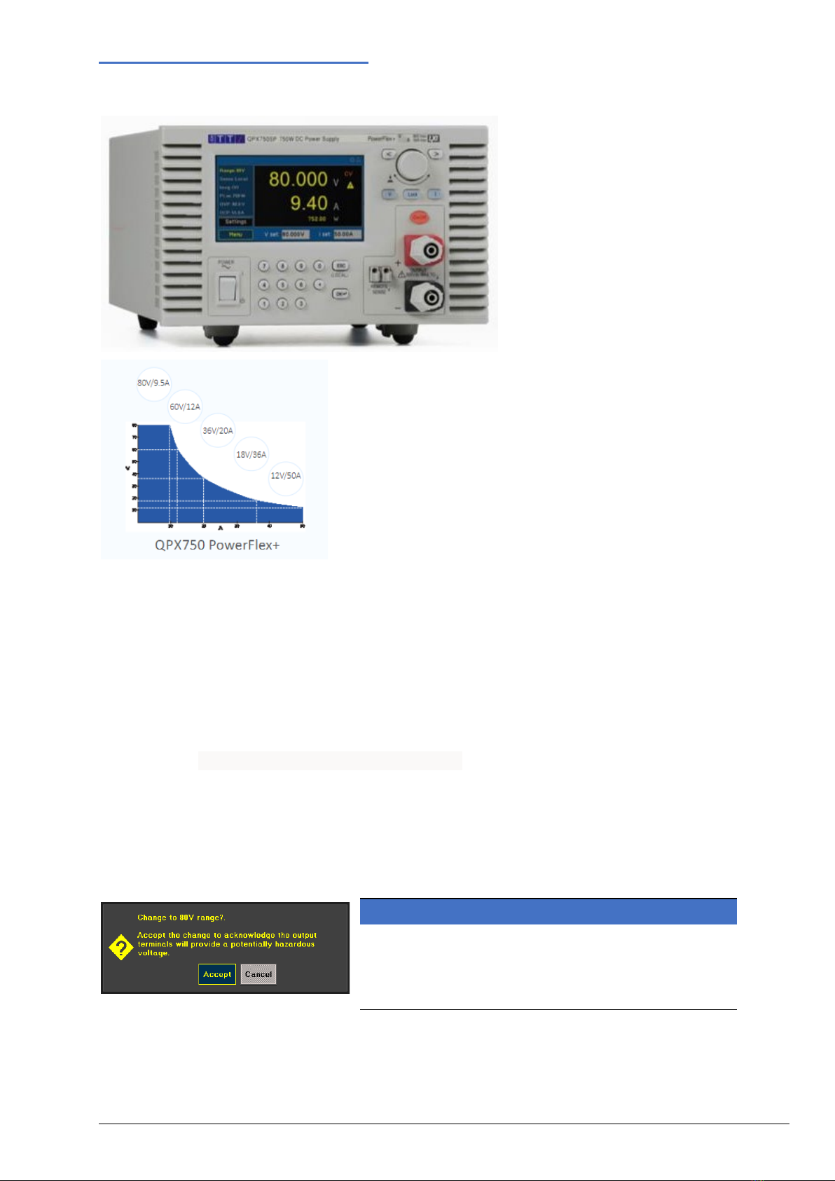
1Product Description.......................................................................................................................2
2Safety...............................................................................................................................................3
2.1 Symbols..................................................................................................................................................3
2.2 Safety notices .........................................................................................................................................4
3Installation ......................................................................................................................................5
3.1 Mounting.................................................................................................................................................5
3.2 Ventilation ...............................................................................................................................................5
3.3 Electrical Requirements..........................................................................................................................5
4Instrument Overview......................................................................................................................6
4.1 Front Panel .............................................................................................................................................6
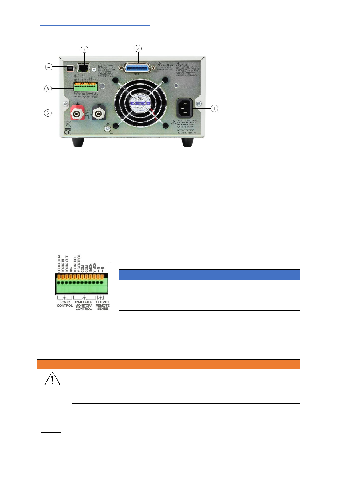
4.2 Rear Panel..............................................................................................................................................8
5Getting Started .............................................................................................................................10
5.1 Using this manual .................................................................................................................................10
5.2 Switching on .........................................................................................................................................10
5.3 Home Screen / Settings Menu.............................................................................................................. 11
5.4 Meter status..........................................................................................................................................12
5.5 Status bar .............................................................................................................................................14
5.6 Navigation controls ...............................................................................................................................15
6Menu ..............................................................................................................................................16
6.1 Instrument.............................................................................................................................................16
6.2 System..................................................................................................................................................20
6.3 Interface................................................................................................................................................21
6.4 Messages .............................................................................................................................................22
6.5 Info........................................................................................................................................................23
6.6 Help ......................................................................................................................................................23
6.7 File Ops ................................................................................................................................................23
6.8 Defaults ................................................................................................................................................24
6.9 Calibration ............................................................................................................................................24
7Messages. .....................................................................................................................................25
7.1 Error Messages ....................................................................................................................................25
7.2 Warning messages ...............................................................................................................................25
7.3 Information messages ..........................................................................................................................25
8Maintenance..................................................................................................................................26
8.1 Cleaning ...............................................................................................................................................26
8.2 Firmware update...................................................................................................................................27
9Remote Operation ........................................................................................................................28
9.1 USB Interface .......................................................................................................................................28
9.2 LAN Interface........................................................................................................................................29
9.3 GPIB Interface ......................................................................................................................................31
9.4 Status Reporting...................................................................................................................................32
9.5 Remote/ local operation........................................................................................................................36
9.6 Parameter Data Format........................................................................................................................37
9.7 Command List ......................................................................................................................................37
9.8 SCPI Commands..................................................................................................................................38
9.9 SCPI Subsystems.................................................................................................................................39
10 Factory default settings...........................................................................................................43
11 Specification .................................................................................................................................44
11.1 Output Specifications............................................................................................................................44
11.2 Meter Specifications .............................................................................................................................45
11.3 Display Features...................................................................................................................................46

1 - Product Description
2QPX750 Instruction Manual
1PRODUCT DESCRIPTION
The QPX750 is a single output laboratory power supply with a
maximum output power of 750 watts.
The PoweFlex+ design provides voltages up to 80V, currents up
to 50A and flexible modes of operation (CC, CV, and CP) with
automatic crossover, while offering an exceedingly wide range
of operation, as detailed in the PowerFlex + curve.
This power supply achieves unusually low noise of <3mV rms at
full power and good transient response of <2ms.
This high feature Power Supply displays load power and load
impedance in addition to measurements of output voltage and
current. The load impedance calculation enables low resistance measurements to be made at high
currents by creating a four-terminal connection, using the remote sense terminals. Also provided is a
meter averaging function to dampen the load current- this can be selected in order to achieve more
accurate results when measuring rapidly varying loads.
This versatile power supply offers Analog and Digital interface for remote control and Test System
integration. Remote Communication is Standard with 2 interfaces: USB and LAN. An optional GPIB
interface is also available. Analog inputs provide remote control of the output volts and current while
Analog outputs provide monitoring of the output Voltage and current. Digital Opto isolated logic
signals provide an input that can control the output state on and off and an output confirms the
operating state; current limit, power limit, or any fault trip.
Housed in a ½ rack width, 3U high case with front input ventilation, an intelligent fan is used to
minimise cooling noise. It is suited to both bench-top and system applications.
The instrument has two ranges: 50V or 8 0 V. The unit is set on the SELV setting of 50V to reduce the
risk of hazardous voltages and simplifying compliance with the safety requirements.
NOTE
By default, the range that allows a maximum of 80V is
disabled. To enable the 80V range- the user must manually
select this range. Before confirming this choice, a warning
will appear to inform of the risk.

2 - Safety
3QPX750 Instruction Manual
2SAFETY
2.1 Symbols
This instruction manual contains information and warnings which must be followed by the user to
ensure safe operation and to retain the instrument in a safe condition.
The following symbols are displayed on the instrument and throughout the manual, to ensure the
safety of the user and the instrument, all information must be read before proceeding.
WARNING
Indicates a hazard that, if not avoided, could result in injury or death.
CAUTION
Indicates a hazard that could damage the product and may result in loss of important
data or invalidation of the warranty.
NOTE
Indicates a helpful tip.
EXAMPLE
Indicates an example to show further details.
Terminal connected to
chassis ground.
Instrument in STANDBY.
l
Mains supply ON.
Alternating current.

2 - Safety
4QPX750 Instruction Manual
2.2 Safety notices
This instrument is:
·A safety Class I instrument according to IEC classification and has been designed to meet the
requirements of EN61010-1 (Safety Requirements for Electrical Equipment for Measurement,
Control and Laboratory Use). It is an Installation Category II instrument intended for operation from
a normal single-phase supply.
·Designed for indoor use in a Pollution Degree 2 environment in the temperature range 5°C to 40°C,
20% - 80% RH (non-condensing).
·Tested in accordance with EN61010-1 and has been supplied in a safe condition. This instruction
manual contains some information and warnings which have to be followed by the user to ensure
safe operation and to retain the instrument in a safe condition.
WARNING
Do not operate while condensation is present.
Do not operate outside its rated supply voltages or environmental range.
THIS INSTRUMENT MUST BE EARTHED.
Ensure that only fuses with the required rated current and of the specified type are used for
replacement.
The use of makeshift fuses and the short-circuiting of fuse holders is prohibited.
Use of this instrument in a manner not specified by these instructions may impair the safety
protection provided.
Any interruption of the mains earth connector, inside or outside, will make the instrument
dangerous. Intentional interruption is prohibited.
Any adjustment, maintenance, and repair of the opened instrument under voltage must be
avoided. When connected, terminals may be live and opening the covers or removal of parts
(except those that can be accessed by hand) may expose live parts.
Voltages above 60VDC are hazardous live according to EN 61010-1 and great care must be
taken when using the power supply at voltages above this level.
Capacitors inside the power supply may still be charged even if the power supply has been
disconnected from all voltage sources but will be safely discharged about 10 minutes after
switching off.
To avoid electric shock, or damage to the instrument, never allow water to get inside the case.
If the instrument is clearly defective, or has been subject to mechanical damage, excessive
moisture, or chemical corrosion, the safety protection may be impaired, and it must be
withdrawn from use and returned for repair.
CAUTION
Do not wet when cleaning, use only a soft dry cloth to clean the screen.
Do not use a sharp or pointed objects to operate the touch screen.
Take care not to restrict the inlet vents at the front, rear, sides or underneath the instrument.
In rack-mounted situations, allow adequate space around the instrument.
This instrument is protected by an internal fuse which is user serviceable (refer to Service Manual).

3 - Installation
5QPX750 Instruction Manual
3INSTALLATION
3.1 Mounting
For rack mounting, the feet should be removed such that the instrument can be fitted beside any
other standard 3U half-rack instrument in a 19” rack. A suitable 3U 19” rack kit is available from the
manufacturer or their overseas agents- a RM460 19-inch rack kit accommodates two instruments.
3.2 Ventilation
The instrument uses a fan, which has variable speed control, fitted to the rear panel. Take care not to
restrict the rear air exit or the inlet vents at the front (sides and underneath). In rack-mounted
situations, allow adequate space around the instrument and/or use a fan tray for forced cooling.
3.3 Electrical Requirements
3.3.1 Mains operating voltage
This instrument has a universal input range and will operate from a nominal 115V to 230V mains
supply without adjustment. Check that the local supply meets the AC input requirement given in the
Specification.
3.3.2 Mains lead
Connect the instrument to the AC supply using the mains lead provided.
Should a mains plug be required for a different mains outlet socket, a suitably rated and approved
mains lead set should be used. Ensure this is fitted with the required wall plug and an IEC60320 C13
connector for the instrument end.
To determine the minimum current rating of the lead-set for the intended AC supply, refer to the
power rating information on the equipment or in the Specification.

4 - Instrument Overview
6QPX750 Instruction Manual
4INSTRUMENT OVERVIEW
4.1 Front Panel
4.1.1 Overview
4.1.2 ①Colour Touch Screen Display
CAUTION
Do not use sharp objects or pointed objects to operate the touch screen.
②Power Switch
Power Switch is located in the bottom left-hand corner. Press to start the unit.
CAUTION
When instrument is in Standby mode, Mains is still present.
③Numeric Keypad
Numeric keys permit direct entry of a value for the parameter currently selected.
④Escape Key/Local/OK
Entry can be abandoned at any point by pressing the ESCAPE key. It will also exit the selection or
screen currently selected. This key is also used to clear output trip conditions, together with their pop-
ups. Additionally, when in remote mode, this key is used to return the instrument to local operation.
The OK key is used to confirm a selection.
⑤Remote Sense Terminals
Allows the user to adjust the voltage at the point of the load. The instrument has a very low output
impedance, but this is inevitably increased by the resistance of the connecting leads and the contact
resistance between terminals and leads. At high currents, this can result in significant differences
between the indicated source voltage and the actual load voltage (even two 2mΩ connecting leads will
drop 0·2V at 50 Amps, for instance). This problem can be minimised by using short, thick, connecting
leads, but where necessary it can be completely overcome by using the remote sense capability.

4 - Instrument Overview
7QPX750 Instruction Manual
CAUTION
Voltage drop on sense leads should not exceed 2V.
NOTE
To avoid instability and transient response problems, care must be taken to ensure good
coupling between each output and sense lead; this can best be done by twisting the leads
together. An electrolytic capacitor directly across the load connection point may also be
beneficial. The voltage drop in each output lead must not exceed 1V.
⑥Output Terminals
The load should be connected to the positive (red) and negative (black) terminals marked OUTPUT.
The terminals accept 4mm plugs into the end (but note that 4mm plugs will only support 30 Amps).
For currents greater than 30A, 6mm diameter wires, plugs or 8mm spade connections (with a
maximum blade width of 16mm) can be accepted into the cross-hole.
WARNING
The wiring and connectors must be capable of supporting the current required; for 50
Amps, 6mm2cable is needed.
WARNING
Voltages above 60VDC are hazardous live according to EN 61010-1 and great care must
be taken when using the power supply at voltages above this level.
Always make connections to the instrument with the OUTPUT off.
CAUTION
Exceeding the maximum reverse voltage (90V) and current (3A) will damage the unit.
⑦ Volts/Amps/Lock
Pressing either V or I to adjust the Voltage or Current, respectively. The LOCK key will light when active,
indicating that the entire front panel is locked. In this mode, only navigation between menus is
permitted. Long press for 3 seconds to deactivate the lock.
⑧ Rotary knob and Directional Keys
The rotary knob is used to navigate the user interface- it features a ‘press’ function to select an option.
See ‘Rotary knob’ for more details.
The direction keys are used for navigating parameter windows and scrolling numeric parameter values.
In addition, the left directional key can be used as a backspace during editing. See ‘Front Panel Keys’
for more details.

4 - Instrument Overview
8QPX750 Instruction Manual
4.2 Rear Panel
①AC power inlet
②GPIB (optional)
Requires GPIB 1A user retrofittable option. The default GPIB address is 11.
③LAN
The LAN interface is designed to meet 1.5 LXI (LAN extensions for Instrumentation) Core 2016.
Remote control using the LAN interface is possible using a TCP/IP Socket protocol.
④USB
The USB port accepts a standard USB cable. The Windows plug-and-play functions should
automatically recognise that the instrument has been connected.
⑤Terminal Block
Press the orange actuators of the screwless terminals, insert the
connecting wire and release the actuator to secure the connection.
NOTE
Minimum recommended cable 0.4mm, maximum. 0.8mm diameter
cable. Always use shrouded ferrules to prevent the risk of shock.
Logic Control:LOGIC COMMON, LOGIC IN, LOGIC OUT, NC (no connection) see ‘Logic Control’for setup
and configuration details. LOGIC IN is connected to the input of an isolating opto-coupler via an 820Ω
resistor in series. The input is activated by an input voltage greater than approximately 3.3V between
LOGIC IN and LOGIC COMMON
LOGIC OUT is an isolated rear-panel open-collector output that will sink up to 2mA when active
CAUTION
Do not apply an input voltage greater than 20V.
Do not apply volts greater than 30Vdc to LOGIC OUT
Analog Control / Monitor: I CONTROL, V CONTROL, COM, COM, I MONITOR, V MONITOR See ‘Analog
Control’ for setup and configuration details.

4 - Instrument Overview
9QPX750 Instruction Manual
V CONTROL and I CONTROL are 0…5V or 0…10V inputs with respect to COM terminal that provide
quasi-analogue control of the Output Voltage and Current Control, respectively.
The output terminal voltage and output current may be monitored on V MONITOR and I MONITOR,
respectively. V MONITOR and I MONITOR are always available at the rear.
CAUTION
V and I CONTROL inputs are differential, with a limited common mode range of ± 2.5Vdc
with respect to the negative output. They should be driven from a ‘floating’ source such
as another power supply.
MONITOR outputs are differential with a limited common mode range of ± 2.5Vdc with
respect to the negative output. They should be connected to a measuring system with
‘floating’ inputs such as a DMM.
Do not apply volts greater than 20VDC to ANALOG CONTROL terminals, with respect to
COM.
Output Remote Sense:-S, +S See 'Remote Sense Terminals’ for more details.
WARNING
ANALOG CONTROL /MONITOR and SENSE terminals are referenced to the output
negative Output terminal. Voltages above 60VDC are hazardous live according to EN
61010-1 and great care must be taken when using the power supply at voltages above
this level.
Always make connections to the instrument with the OUTPUT off.
⑥Output Terminals
Refer to Output Terminals on front panel.
NOTE
The M4 threaded screw marked provides a connection point to safety earth ground.
A M4 Ring tab must be used, with an appropriate washer

5 - Getting Started
10 QPX750 Instruction Manual
5GETTING STARTED
5.1 Using this manual
This section is a general introduction to the operation of the instrument and is intended to be read
before using the Power Supply for the first time.
In this manual front panel keys and sockets are shown in capitals, e.g. ON, OFF.Text, entry fields and
messages displayed on the LCD are shown in a different font, e.g. V Set, I Set.
The descriptions in this manual relate to using the instrument via the touch screen, alternatively, the
hard keys and rotary knob can be used. See ‘Navigation Controls’ for details on how to use the
instrument in this way.
Throughout this manual, the navigation through menus will be shown at the top of a section using the
following format:
Menu>Sub Menu>Option
NOTE
The pop-up screens for parameters will only occur when using the touch screen.
Trip/System Failure, Error, and Warning pop-up screens will appear when using any form
of navigation.
5.2 Switching on
Connect the instrument to the AC supply using the mains lead provided.
Press the POWER switch. At power up, the instrument displays a start-up message whilst initialising
the application.
Loading takes a few seconds, after which the home screen is displayed.
WARNING
To fully disconnect from the AC supply, unplug the mains cord from the back of the
instrument or switch off at the AC supply outlet; make sure that the means of
disconnection are readily accessible. Disconnect from the AC supply when not in use.

5 - Getting Started
11 QPX750 Instruction Manual
5.3 Home Screen / Settings Menu
The Home Screen will be shown when the instrument is
powered on. It will include the default parameters.
To set volts or amps, select the parameter window and
enter the value required. See ‘Navigation controls'for
more details.
Use the ON/OFF key on the front panel to turn the
output on.
The home screen and settings menus are designed to be used in conjunction with one another using
the Settings and buttons.
①
STATUS BAR
Shows current status of the instrument. See ‘Status Bar' for more details.
②
METER
Displays the live volts/amps present at the output terminals. See ‘Meter Status’
③
INFORMATION
Lists the set information from the settings menu.
④
EDITABLE PARAMETERS
V set
Set DC output voltage. Values are dependent on selected range.
I Set
Set DC output current limit. Values are dependent on selected range.
Range
Select operating range- 50Vor 80V.
50V in steps of 1mV, 80V in steps of 2mV.
As the resolution of the 80V range is 2mV, when switching from 50V to 80V range
the set-point will be rounded down to the nearest 2mV figure (e.g., if output is set to
49.997 it will be changed to 49.996).
Plim
Set the power limit, this can also be used to regulate the power being delivered by
the unit: 100W to 750W in 10W increments
OVP
Set the Over Voltage Protection limit. Protects against dangerously high voltages: 2V
to 90V
OCP
Set the Over Current Protection limit. Protects against excessive current: 2A to 55A
Sense
Select how the voltage is regulated.
Local: Instrument will regulate set voltage
Remote: Instrument will regulate set voltage at the point the remote sensing wires
are connected.
Iavg
Select Current Averaging: The AMPS reading is still updated at the same rate (4
times per second), but the value displayed is a filtered rolling average of the last 4
current measurements made.
On: The measured current value at the output terminals is filtered and displayed.
Off: A sample of the measured output current value is shown on the display.
⑤
Navigation
BUTTONS
Settings: Allows editing of the set parameters in the information box, shown in ③
Menu: Contains all system and instrument setups, see ‘Menu’ for more details.
Back: Return to the previous screen.
①
③
②
④
⑤
②
④

5 - Getting Started
12 QPX750 Instruction Manual
5.4 Meter status
The following symbols may appear in the meter display:
Mode With the output on, the mode shown will be: CV (Constant Voltage), CC (Constant Current) or
CP (Constant Power), depending on the set limits and load conditions. The display will show
the actual output voltage and current at the terminals.
CV Constant Voltage: Power supply will regulate at set voltage, provided the current and power
are less than Iset and Plim, respectively.
CC Constant Current: Power supply will regulate at set current, provided the voltage and power
are less than Vset and Plim, respectively.
CP Constant Power: Power supply will regulate at the set power, provided the voltage and current
are less than Vset and Iset respectively.
PowerFlex+ allows you to set voltage and currents that result in power greater than the power
curve- in this case the active mode will depend on the load.
EXAMPLE
Setting the instrument to:
Vset 36V, Iset 36A & Plim 750W.
Note: 36Vx36A = 1296W this is greater than max
2Ω load: display; 36V, 18A and 648W: CV mode
0.5Ω load: display; 18V, 36A and 648W: CC mode
1Ω load: display; ≈27V, ≈26A and 720W:CP mode
Protection
The OVP or OCP circuits will trip if an excessive voltage or current is accidentally set from the
front panel (via a remote-control interface) or is the result of a failure in the control circuitry of
the instrument itself. OVP will also trip if an excessive voltage is impressed across the
terminals from an external source; however, when the output is tripped off, the external
voltage will still be present, and it is up to the user to remove the source to avoid possible
damage.
OVP Over Voltage Protection trip – If the output voltage exceeds the set OVP the output will
immediately turn off (typically within 100µs), thus avoiding damage to the circuit under test.
OCP Over Current Protection trip- If the output current exceeds the set OCP the output is shut
down (typically within 100ms), thus avoiding damage to the circuit under test.
High Voltage Mode active- The instrument is set to the 80V range and could provide
potentially hazardous voltages.
NOTE
It is possible to set OVP or OCP below Vset or Iset.This often results in the power supply
unexpectedly turning the output off and can be used to turn the output off if the load
changes and you do not want the voltage or current to fold back.

5 - Getting Started
13 QPX750 Instruction Manual
5.4.1 Meter colours
If the output is switched off, the meter volts and current will be displayed in
Grey.
If the output is turned on the active volts will be shown in Yellow.
If the output is turned off but there are still volts present from an external
source, that voltage measurement is shown in Red. Measured volts will show
in Red until the output caps are discharged. The pre-set values will then be
shown in Grey.
5.4.2 Load Impedance and power calculations
When the output is on, calculated load impedance
(Ω) and output power (W) can be viewed on the
meter underneath the voltage and current readings
(Power only on Home Screen). The calculated load
impedance function enables low resistance
measurements to be made at high currents, e.g.,
RDS(on) of power MOSFETs., by creating a four-
terminal connection, using the remote sense
terminals.
NOTE
Always use the Remote Sensing function to eliminate the effects of connecting lead and
contact resistance when making low value V/A measurements. See 'Remote Sense
Terminals’ for more information.

5 - Getting Started
14 QPX750 Instruction Manual
5.5 Status bar
①Analog Control
When choosing an active option on ‘Analog Control’, the choice of: V Only, I Only, V&I will appear in
the status bar.
②Sense Trip
If SNS Trip appears, a sense error has occurred and caused a trip. The output is tripped off if the
voltage between an output terminal and its corresponding sense terminal exceeds approximately 2V;
this will happen if the sense wires are wired at the load to the wrong output or if an attempt is made
to draw power from the sense wires. If the sense terminals are mis wired in this way the output is
turned off and a pop-up will appear notifying of the trip; pressing ESCAPE at this point removes the
message, pressing OK will remove the pop-up but SNS Trip will remain in the status bar. The display
will now show the pre-set voltage and current limit. When the cause of the trip has been corrected,
the output can be turned on again.
③Remote status
·REM : This symbol will appear once the instrument starts to receive communications
from any of the remote interfaces.
·: This symbol will appear if an error has occurred while using a remote interface,
it can be viewed in ‘Remote Error Messages’.
·GPIB (optional): When a GPIB connection is detected, the GPIB icon will become
activated.
·USB: When a USB connection is detected, the USB icon will become activated.
·LAN: The LAN field in the Status Line can show multiple status indications:
There is no LAN connection, for example no cable connected.
·Successfully connected.
·(Flashing icon) Configuring LAN connection.
·Unsuccessful attempt to connect.

5 - Getting Started
15 QPX750 Instruction Manual
5.6 Navigation controls
The versatile user interface can be navigated using the touch screen, rotary knob, front panel keys or a
combination of all three options.
Many settings can be made quickly and easily using the touch screen alone; the rotary knob is most
useful when, for example, a parameter is being frequently increased or decreased during manual
testing. Using the front panel keys is a quick way to directly edit when frequently changing a value.
There are two types of field; both of which are explained in this manual. A ‘button’- ①- will apply an
action. A ‘parameter’- ②- will provide a list of options for the user to choose.
5.6.1 Touch screen
Touch to select an editable field, touch again to adjust the field. An editing screen will appear- enter
the required values and touch OK. Editing screens will vary depending on field type, this could be a
numeric keypad, QWERTY keypad or unique options related to that field. See appropriate menus for
more details.
5.6.2 Front Panel Keys
Use the < > keys to highlight the actionable field
and press OK. When editing a numeric field,
pressing a number key will begin editing, other
field type options can be viewed using the rotary
encoder- press the OK key to action the change.
To directly edit set volts or amps, press the Vor I key followed by number keys, press OK to action.
Editing state on a numeric field using the front panel numeric keys:
5.6.3 Rotary knob
The rotary knob offers two different states of editing – 2 State (default setting – detailed below) and 3
State. For further information, see ‘Encoder State Adjust’.
Press to initiate the rotary knob and turn to highlight the actionable fields from top to bottom, left to
right. To select a field, press the knob. When an editable field is selected, adjustments can be made by
turning the knob until the required value is selected. Press the knob to action the change.
Editing state on a numeric field with rotary knob:
①
②

6 - Menu
16 QPX750 Instruction Manual
6MENU
This gives access to the menus used to:
·Set up operational parameters for the
instrument, system, and remote interface.
·View messages, instrument information, and
Help menus.
·Save and recall instrument setup.
·Calibrate the instrument.
6.1 Instrument
Menu> Instrument
This menu allows the user to set or recall the
operational parameters that affect instrument use.
6.1.1 Power-on State
Menu>System>Power-ON State
These editable parameters determine what setting
the power supply switches on with.
NOTE
Always Off and Default Params.if a safe power up is
required.
As Power Down and Latest Params. If a long-term test is
running and the user wishes to restart automatically.
Output State:
·Always Off: Output will remain off until manually set.
·As Power Down: Output will reset at the previously
set state when the instrument was switched off.
Parameters:
·Latest Params: Instrument will automatically load
parameters the unit was powered down with.
·Default Params: Unit will power up with the
default values - see ‘Factory default settings’
for more information.

6 - Menu
17 QPX750 Instruction Manual
6.1.2 Analog Control
Menu>Instrument>Analog Control
Analog signal connections V CONTROL and I CONTROL are available from the terminal block on the
‘Rear Panel’. These can provide quasi-analog control
of Output Voltage and Current Limit, respectively.
Control Type:
·None: deselects the analog input, output voltage is
controlled by Vset and Iset
·V only: Enables analog control of the output voltage
and disables Vset from front panel and remote.
·I Only: Enables analog control of the output and
disables Iset from front panel and remote.
·V&I: Enables analog control of both output voltage
and output current.
Range Selected:
Sets the control voltage full scale range. Used to
control Vset, Iset or V&I
·0…10V
·0…5V
EXAMPLE
Setting: Range to 50V, Control type to V&I and Range selected to 0…10V.
Supply 0-5 volts into VCONTROL with respect to COMMON from a floating source i.e.,
PSU.
Applying 0V will result in 0V appearing on the Output Terminals
Applying 1V will result in 5V appearing on the Output Terminals
NOTE
The inputs are read 4 times per second by the A-
to-D converter and the output is set according to
the selected input scaling range. See 'Terminal
Block’ for hardware configuration details. When
Analog Control is active, the parameter fields are
no longer editable for the activated control type
as the output is now controlled by the input on
the rear terminal block.

6 - Menu
18 QPX750 Instruction Manual
6.1.3 Logic Control
Menu>Instrument>Logic Control
Digital signal connections LOGIC IN and LOGIC OUT
are available from the terminal block on the ‘Rear
Panel’.
Logic Out
LOGIC OUT is an isolated rear-panel, open-collector output that will sink up to 2mA when active
(‘switch closure’); the LOGIC OUT can be set to be ‘closed on’ or ‘closed off’ for instrument operating
states: current limit (CC mode), power limit (CP mode), or for any fault trip. The default condition is for
LOGIC OUT to be ‘closed’ for the output on. Loss of AC power, which would deactivate the opto, is also
reliably detected with this setting.
Logic Out has the following states:-
·O/P On –Main output is turned on.
·Trip - Any fault trip condition O V P, O C P etc.
·CP- PSU operates in Constant Power regulation mode.
·CC- PSU operates in Constant Current regulation mode.
Logic In
LOGIC IN is connected to the input of an isolating opto-coupler via an 820Ω resistor in series. The input
is activated by an input voltage greater than approximately 3.3V between LOGIC IN and LOGIC
COMMON.
Logic In has the following states:-
·Ignored: Will not affect output.
·Enable O/P: Instrument will enable the output.
·Disable O/P: Instrument will disable the output.
NOTE
•LOGIC IN can only be used to enable/disable the output if the output has already been turned
on with the front panel key or by remote interface command; this permits the front panel key
to be used to turn the output off in an emergency, i.e., to override LOGIC IN. Having turned
the output on with the key, the ON/OFF key remains illuminated even when the output is
disabled by the LOGIC IN signal.

6 - Menu
19 QPX750 Instruction Manual
6.1.4 Save
Menu>Instrument>Save
Instrument setups can be saved as a file to the
internal storage, these settings include:
·Set volts, current and power limit
·Selected Range
·Over voltage and Over current protection
·Sense terminal setup
·Current averaging settings
·Power on state
·Logic control settings
·Analog control settings
The file name can be up to 8 characters and a combination of uppercase letters, numbers, and “- _”
symbols.
6.1.5 Recall
Menu>Instrument>Recall
Recall a previously saved instrument setup file from
the Internal Storage.
Use the keys to choose.
The files can be sorted into alphabetical order using the
^ file name(s) button.
The selected file to be recalled is highlighted in white.
Press Recall applying saved setup.
Table of contents
Other AimTTi Power Supply manuals

AimTTi
AimTTi MX Series User manual

AimTTi
AimTTi CPX200D User manual

AimTTi
AimTTi PowerFlex QPX1200 Series User manual

AimTTi
AimTTi MX User manual

AimTTi
AimTTi EX354RD User manual

AimTTi
AimTTi MX100Q User manual

AimTTi
AimTTi QPX600D User manual

AimTTi
AimTTi EX4210R User manual

AimTTi
AimTTi MX180T User manual

AimTTi
AimTTi CPX400D User manual