manuals.online logo
Brands
  1. Home
  2. •
  3. Brands
  4. •
  5. AimTTi
  6. •
  7. Power Supply
  8. •
  9. AimTTi MX Series User manual

AimTTi MX Series User manual

This manual suits for next models

6

Other AimTTi Power Supply manuals

AimTTi MX100Q User manual

AimTTi

AimTTi MX100Q User manual

AimTTi MX100Q User manual

AimTTi

AimTTi MX100Q User manual

AimTTi CPX400D User manual

AimTTi

AimTTi CPX400D User manual

AimTTi QPX750SP User manual

AimTTi

AimTTi QPX750SP User manual

AimTTi EX354RD User manual

AimTTi

AimTTi EX354RD User manual

AimTTi MX100T User manual

AimTTi

AimTTi MX100T User manual

AimTTi EX355R User manual

AimTTi

AimTTi EX355R User manual

AimTTi MX User manual

AimTTi

AimTTi MX User manual

AimTTi QPX1200S User manual

AimTTi

AimTTi QPX1200S User manual

AimTTi CPX400S User manual

AimTTi

AimTTi CPX400S User manual

AimTTi QPX600D User manual

AimTTi

AimTTi QPX600D User manual

AimTTi MX180T User manual

AimTTi

AimTTi MX180T User manual

AimTTi PowerFlex QPX1200 Series User manual

AimTTi

AimTTi PowerFlex QPX1200 Series User manual

AimTTi CPX200D User manual

AimTTi

AimTTi CPX200D User manual

AimTTi EX1810R User manual

AimTTi

AimTTi EX1810R User manual

AimTTi EX4210R User manual

AimTTi

AimTTi EX4210R User manual

AimTTi QL Series II User manual

AimTTi

AimTTi QL Series II User manual

Popular Power Supply manuals by other brands

Videx 520MR Installation instruction

Videx

Videx 520MR Installation instruction

Poppstar 1008821 Instructions for use

Poppstar

Poppstar 1008821 Instructions for use

TDK-Lambda LZS-A1000-3 Installation, operation and maintenance manual

TDK-Lambda

TDK-Lambda LZS-A1000-3 Installation, operation and maintenance manual

TDK-Lambda 500A instruction manual

TDK-Lambda

TDK-Lambda 500A instruction manual

Calira EVS 17/07-DS/IU operating instructions

Calira

Calira EVS 17/07-DS/IU operating instructions

Monacor PS-12CCD instruction manual

Monacor

Monacor PS-12CCD instruction manual

VOLTIMA MagicBox 15 Installation and operating instructions

VOLTIMA

VOLTIMA MagicBox 15 Installation and operating instructions

Miller Auto Deltaweld 452 owner's manual

Miller

Miller Auto Deltaweld 452 owner's manual

BCP PUOUBK How to install

BCP

BCP PUOUBK How to install

HC 2210 manual

HC

HC 2210 manual

Agilent Technologies 6032A Service manual

Agilent Technologies

Agilent Technologies 6032A Service manual

Radial Engineering SB-48UB user guide

Radial Engineering

Radial Engineering SB-48UB user guide

Puls CT5.241 installation manual

Puls

Puls CT5.241 installation manual

OCZ ZX1250W Technical specifications

OCZ

OCZ ZX1250W Technical specifications

iseg ECH 238 manual

iseg

iseg ECH 238 manual

Agilent Technologies 6631B Service manual

Agilent Technologies

Agilent Technologies 6631B Service manual

Power XXL A Series instruction manual

Power

Power XXL A Series instruction manual

HP 6200B Operating and service manual

HP

HP 6200B Operating and service manual

manuals.online logo
manuals.online logoBrands
  • About & Mission
  • Contact us
  • Privacy Policy
  • Terms and Conditions

Copyright 2025 Manuals.Online. All Rights Reserved.

GPIB Opon Fing Instrucons
For Product Series:
MX, TSX, TGF,
TG, TGP, TGR & QPX
ATTENTION!
Observe precauons for handling
electrostac sensive devices.
WARNING!
Disconnect the instrument from all
voltage sources and leave for 10
minutes before removing the cover.
CAUTION!
Only use ngs provided.
Instrucon leaet 48591-1290 Issue 5
Aim Thurlby Thandar Instruments Ltd Glebe Road,
Hunngdon, Cambridgeshire PE29 7DR, England
Telephone: +44 (0)1480 412451
e mail: sales@aim.com
www.aim.com
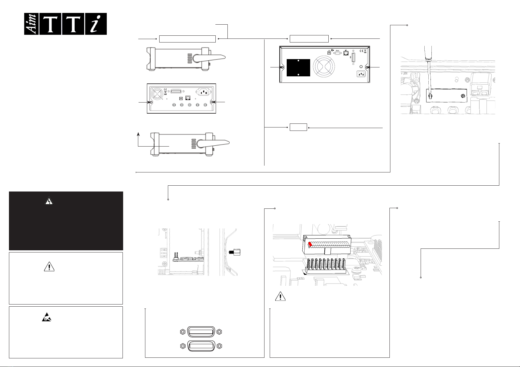
STEP 1: REMOVE COVER
Connect the at cable to the 20 Pin
header labelled ‘GPIB’ (‘PJ14A’-TG5011
& TG2511/‘PJ7’-MX/'PJ8'- QPX), with pin
1 to the white dot (red stripe next to the
white triangular corner marker).
Remove the two plasc push-rivets
that secure the rear panel GPIB
socket blanking plate (it is easiest to
push out the centre-pin of the rivet
from the inside of the rear panel).
Holding the GPIB board at the edges,
place the board so that the GPIB
connector is protruding through the rear
panel and fasten using the two M4 hex
screws provided (Torque 40cNm).
STEP 6:
CONNECT
Replace the top cover and re-t the
screws in reverse order of step 1.
See the instrument’s
instrucon manual for details
on how to acvate and use the
ed GPIB. This can be found
at www.aim.com/support
STEP 2:
REMOVE BLANKING PLATE
STEP 3:
FIT GPIB BOARD
STEP 4:
CONNECT GPIB BOARD
STEP 5:
REPLACE COVER
MX & QPX
TGF, TG, TGP & TGR
1. Posion the handle as shown.
2. Remove 2x screws from rear panel.
3. Slide and li the cover clear of the instrument.
1. Remove 2x screws from the outer
edge of the rear panel.
2. Li the cover clear of the instrument
LAN
RS232
USB
GPIB
LAN
RESET
-
-
-
-
-
-
-
-
-
-
-
-
S
-
S
-
S
-
S
-
S
+
S
+
S
+
S
+
O/P 3 O/P 2
O/P
4 O/P 1
󰣕
󰣒
TSX
1. Remove 6x screws from side panels.
2. Li the cover clear of the instrument
LONG CABLE FOR MX & QPX ONLY, SEE
BACK OF SHEET FOR FOLDING INSTRUCTIONS
I/F Board
I/F Board
GPIB
GPIB
✖✔
② FOLDING THE CABLE:
Fold the cable as shown.
MX & QPX SERIES ONLY: USE 140mm CABLE
• Fit cable to I/F board rst.
• Fold cable back to run
along the TOP of the I/F
board.
• Run the cable down the
side of the I/F board.
• Fit to GPIB board.
I/F END
GPIB END
Red
Stripe
③ FITTING THE CABLE:
① CABLE POSITIONING:
CAUTION The cable MUST NOT sit below the I/F board.
I/F Board
GPIB
Red
Stripe
MX SERIES QPX SERIES
Control Board
GPIB
✖✔
② FOLDING THE CABLE:
Fold the cable as shown. • Fit cable to GPIB board
rst.
• Fit to control board.
• Fold the excess cable
away from the GPIB
board.
GPIB END
Red
Stripe
③ FITTING THE CABLE:
① CABLE POSITIONING:
CAUTION The cable MUST NOT sit below the control board.
Control Board
GPIB
CTRL END
Red
Stripe
GPIB
Control
Board