AimTTi CPX200D User manual

CPX200D & DP
PowerFlex Dual DC Power Supply
INSTRUCTION MANUAL

1
Table of Contents
Specification 2
Safety 5
Installation 6
Connections 7
Manual Operation 9
Remote Interface Operation (CPX200DP only) 15
Remote Commands (CPX200DP only) 25
Maintenance 30
Note: The latest revisions of this manual, device drivers and software tools can be
downloaded from: http://www.aimtti.com/support.
This manual is 48511-1720 Issue 8

2
Specification
General specifications apply for the temperature range 5°C to 40°C. Accuracy specifications apply
for the temperature range 18°C to 28°C after 1 hour warm-up with no load and calibration at 23°C.
Typical specifications are determined by design and are not guaranteed.
OUTPUT SPECIFICATIONS
Voltage Range:
0V to 60V
Current Range:
0A to 10A
Note: In manual operation, actual maxima for voltage and current are typically 1% greater than the
figures given above.
Power Range:
Up to 180W
Output Voltage Setting:
By coarse and fine controls.
Output Current Setting:
By single logarithmic control.
Operating Mode:
Operating Ranges: Four selectable ranges: 60V/10A, 60V/3A, 16V/10A and Custom Limits.
Any V/I setting of the 60V/3A or 16V/10Aranges always falls within the
appropriate part of the Power Envelope.
The 60V/10A range permits any setting up to 60V and 10A but the output will
become unregulated if operated outside of the Power Envelope, see above.
The voltage and current limits of the Custom Limits range can be set to any
Vmax between 0.1V & 60V and Imax between 0.01A and 10A. This facility is
most useful in limiting operation to a particular part of the Power Envelope.
Settings Lock:
(S-Lock)
Voltage and current settings can be locked by a single button press.
Lock accuracy is equal to meter accuracy (see Meter Specification)
Output Switch:
Electronic. Preset voltage and current displayed when off.
Output Terminals: Front panel: Universal 4mm safety binding posts on 19mm (0·75”) pitch.
Rear Panel: Barrier strip connections (CPX200DP only)
Output Sensing: Switchable between local and remote. Remote connection by spring-loaded
push terminals on front panel and barrier strip on rear panel (CPX200DP only).
Output Protection: Forward protection by Over-Voltage Protection (OVP) and Over-Current
Protection (OCP) trips.
Reverse protection by diode clamp for reverse currents up to 3A.
OVP Range: 1V to 66V set by front panel screwdriver adjustment or via the remote
interfaces (CPX200DP only). Setting resolution: 100mV. Accuracy: ± (1% of
setting ± 200mV). Response time: Typically 1ms. Maximum voltage that
should be applied across the terminals is 70V.
OCP Range: Measure-and-compare over-current protection is implemented in firmware and
can only be set via the remote interfaces (CPX200DP only).
Setting resolution: 10mA. Accuracy: ± (0.3% of setting ± 30mA).
Response time: typically 500ms.
For CPX200D, OCP is fixed at 11A.
Constant voltage (CV) or constant
current (CC) with automatic cross-
over, provided that the power
demanded stays within the power
envelope, see graph. Outside of
this envelope the output becomes
unregulated.
CPX200D & DP
Power Envelope
(per channel)

3
Over-temperature
Protection:
The output will be tripped off if a fault causes the internal temperature to rise
excessively.
Line Regulation: Change in output for a 10% line change:
Constant voltage: <0.01% of maximum output
Constant current: <0.01% of maximum output
Load Regulation: Change in output for any load change within PowerFlex envelope, remote
sense connected:
Constant voltage: <0.01% of maximum output
Constant current: <0.05% of maximum output
Ripple & Noise
(20MHz bandwidth):
Both outputs loaded at 16V/10A , CV mode:
Typically <1mVrms, <15mV pk-pk; 3mVrms max.
Transient Load
Response: <250us to within 50mV of set level for a 5% to 95% load change.
Voltage Programming
Speed (CPX200DP only): Typical time required for output to settle within 1% of its total excursion (for
resistive load). Excludes command processing time.
Range and Setting 90% Load No Load 90% Load No Load
60V 3A
16V 10A
Up
Up
15ms
5ms
10ms
5ms
Down
Down
200ms
20ms
2s
1.5s
Temperature Coefficient:
Typically <100ppm/°C
Status Indication: Output ON lamp.
Constant voltage mode lamp.
Constant current mode lamp.
Unregulated (power limit) lamp
Remote lamp (CPX200DP only)
LAN lamp
Trip message on display.
METER SPECIFICATIONS
Meter Types:
Dual 4 digit meters with 10mm (0.39") LEDs. Reading rate 4 Hz.
Meter Resolutions:
10mV, 10mA
Meter Accuracies: Voltage 0.1% of reading ± 2 digits
Current 0.3% of reading ± 2 digits
ADDITIONAL SPECIFICATIONS
Independent Mode: Each output is fully independent and isolated. Operation is equivalent to two
single power supplies.
VoltageTracking Mode:
(VTRACK)
Tracking Accuracy:
With VTRACK selected the voltage controls of Output 1 (the Master) set an
identical voltage on Output 2. The outputs remain isolated and the current
controls remain independent.
Locking the Master (S-Lock) also locks the voltage of Output 2.
Slave voltage = Master voltage ± (0.1% of Master voltage ± 20mV)
Synchronous On/Off: In addition to the independent DC On/Off controls for each output, the outputs
can be turned on or off simultaneously using the Synchronous On/Off key.
This key operates in all modes.

4
DIGITAL INTERFACES (CPX200DP only)
Full digital remote control facilities are available through the RS232, USB, LAN and GPIB
interfaces.
Voltage Setting:
16-bit, Resolution 10mV, Accuracy ± (0·05% +10mV)
Current Setting:
16-bit, Resolution 1mA, Accuracy ± (0·3% + 0·005A)
RS232:
Standard 9-pin D-connector. Baud rate 9600.
GPIB:
Conforming with IEEE488.1 and IEEE488.2
USB:
Standard USB 2.0 hardware connection. Operates as a virtual COM port.
LAN:
Ethernet 100/10base-T hardware connection. 1.4 LXI Core 2011.
Remote Command
Processing Time: Typically <25ms between receiving the command terminator for a step
voltage change at the instrument and the output voltage beginning to
change.
GENERAL
AC Input: 110V – 240V AC ± 10%, 50/60Hz.
Installation Category II.
Power Consumption:
600VA max.
Operating Range:
+5ºC to +40ºC, 20% to 80% RH.
Storage Range:
−40ºC to + 70ºC.
Environmental:
Indoor use at altitudes up to 2000m, Pollution Degree 2.
Safety & EMC: Complies with EN61010-1 & EN61326-1.
For details, request the EU Declaration of Conformity for this instrument
via http://www.aimtti.com/support (serial no. needed).
Size: 210 x 130 x 375mm (WxHxD) half rack width x 3U height
(optional rack mounting kit available).
Weight: 5.4kg

5
Safety
This power supply is a Safety Class I instrument according to IEC classification and has been
designed to meet the requirements of EN61010-1 (Safety Requirements for Electrical Equipment
for Measurement, Control and Laboratory Use). It is an Installation Category II instrument intended
for operation from a normal single phase supply.
This instrument has been tested in accordance with EN61010-1 and has been supplied in a safe
condition. This instruction manual contains some information and warnings which have to be
followed by the user to ensure safe operation and to retain the instrument in a safe condition.
This instrument has been designed for indoor use in a Pollution Degree 2 environment in the
temperature range 5°C to 40°C, 20% - 80% RH (non-condensing). It may occasionally be
subjected to temperatures between +5°C and –10°C without degradation of its safety. Do not
operate while condensation is present.
Use of this instrument in a manner not specified by these instructions may impair the safety
protection provided. Do not operate the instrument outside its rated supply voltages or
environmental range.
WARNING! THIS INSTRUMENT MUST BE EARTHED
Any interruption of the mains earth conductor inside or outside the instrument will make the
instrument dangerous. Intentional interruption is prohibited. The protective action must not be
negated by the use of an extension cord without a protective conductor.
When the instrument is connected to its supply, terminals may be live and opening the covers or
removal of parts (except those to which access can be gained by hand) is likely to expose live
parts. The apparatus shall be disconnected from all voltage sources before it is opened for any
adjustment, replacement, maintenance or repair. Capacitors inside the power supply may still be
charged even if the power supply has been disconnected from all voltage sources but will be safely
discharged about 10 minutes after switching off power.
Any adjustment, maintenance and repair of the opened instrument under voltage shall be avoided
as far as possible and, if inevitable, shall be carried out only by a skilled person who is aware of
the hazard involved.
If the instrument is clearly defective, has been subject to mechanical damage, excessive moisture
or chemical corrosion the safety protection may be impaired and the apparatus should be
withdrawn from use and returned for checking and repair.
Make sure that only fuses with the required rated current and of the specified type are used for
replacement. The use of makeshift fuses and the short-circuiting of fuse holders is prohibited.
Do not wet the instrument when cleaning it.
The following symbols are used on the instrument and in this manual:-
Earth (ground) terminal.
mains supply OFF.
l
mains supply ON.
alternating current (ac)

6
Installation
Mains Operating Voltage
This instrument has a universal input range and will operate from a nominal 115V or 230V mains
supply without adjustment. Check that the local supply meets the AC Input requirement given in
the Specification.
Mains Lead
Connect the instrument to the AC supply using the mains lead provided. Should a mains plug be
required for a different mains outlet socket, a suitably rated and approved mains lead set should be
used which is fitted with the required wall plug and an IEC60320 C13 connector for the instrument
end. To determine the minimum current rating of the lead-set for the intended AC supply, refer to
the power rating information on the equipment or in the Specification.
WARNING! THIS INSTRUMENT MUST BE EARTHED.
Any interruption of the mains earth conductor inside or outside the instrument will make the
instrument dangerous. Intentional interruption is prohibited.
Ventilation
The power supply is cooled by an intelligent multi-speed fan which vents at the rear. Take care not
to restrict the air inlets at top, bottom and side panels or the exit at the rear. In rack-mounted
situations allow adequate space around the instrument and/or use a fan tray for forced cooling.
Mounting
This instrument is suitable both for bench use and rack mounting. It is delivered with feet for bench
mounting. The front feet include a tilt mechanism for optimal panel angle.
A rack kit for mounting one or two of these Half-width 3U high units in a 19” rack is available from
the Manufacturers or their overseas agents.

7
Connections
Front Panel Connections
The load should be connected to the positive (red) and negative (black) terminals marked
OUTPUT. The OUTPUT terminals are rated at 30A.
Remote sense connections to the load, if required, are made from the positive (+) and
negative (−) SENSE terminals. Switch the LOCAL/REMOTE switch to REMOTE when remote
sensing is required. Switch back to LOCAL when remote sensing is not in use.
The terminal marked is connected to the chassis and safety earth ground.
Rear Panel Connections (CPX200DP only)

8
The output and sense terminals for OUTPUT1 and OUTPUT2 are duplicated on the rear panel
terminal blocks and are marked +,
−
, +S and −S. These connections are paralleled with their
front panel equivalents.
Switch the LOCAL/REMOTE switch to REMOTE when remote sensing is required. When the rear
panel Output terminals are used, the use of remote sense is always recommended to ensure that
output regulation is maintained within specification; connections can be made to either the front or
the rear remote sense terminals but never to both pairs of terminals at the same time. Switch back
to LOCAL when remote sensing is not in use.
RS232 (CPX200DP only)
9−pin female D−connector with pin connections as shown below. Can be connected to a standard
PC port using a fully wired 1:1 male-female cable without any cross-over connections.
Pin Name Description
1
RI
Passively asserted (+V through 10k
Ω
)
2
TXD
Transmitted data from instrument
3
RXD
Received data to instrument
4
CTS
5
GND
Signal ground
6
RTS
Passively asserted (+V through 10k
Ω
)
7
DSR
No internal connection
8
DTR
9
CD
No internal connection
Signal ground is connected to instrument ground.
USB (CPX200DP only)
The USB port is connected to instrument ground. It conforms with USB 2.0 (Full Speed) and
accepts a standard USB cable. The Windows plug-and-play functions should automatically
recognise that the instrument has been connected. If the correct driver is not found, follow the
Windows on-screen prompts and install the required files from the CD supplied.
LAN (CPX200DP only)
The LAN interface is designed to meet 1.4 LXI ( Lan eXtensions for Instrumentation) Core 2011.
Remote control using the LAN interface is possible using a TCP/IP Socket protocol. The
instrument also contains a basic Web server which provides information on the unit and allows it to
be configured. Since it is possible to misconfigure the LAN interface, making it impossible to
communicate with the instrument over LAN, a LAN Configuration Initialise (LCI) mechanism is
provided via a recessed switch on the rear panel (marked LAN RESET) to reset the unit to the
factory default.
Further details are given in the Remote Operation chapter. For more information on LXI standards
refer to www.lxistandard.org/home
GPIB (CPX200DP only)
The GPIB signal grounds are connected to the instrument ground. The implemented subsets are:
SH1 AH1 T6 TE0 L4 LE0 SR1 RL2 PP1 DC1 DT0 C0 E2
The GPIB address is set from the front panel.

9
At power on, the factory default setting is for the output to be off. The
preset output volts and current will be determined by the present control
settings and shown in the display. The VIEW lamp is lit to indicate that it is
the preset values that are being displayed.All other settings will be the
same as they were at last power off.
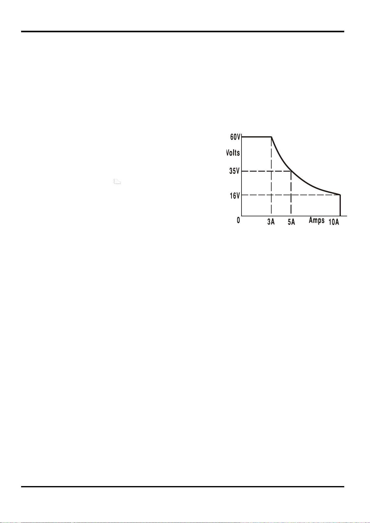
PowerFlex range which limits the maximum
current at the set voltage to that determined
by the power envelope or 10A, whichever is
the lower, see Power Limit paragraph later in
this section.
ON
OUTPUT
Manual Operation
The operation of both outputs is identical; the following description applies to both.
Switching On
The power switch is located at the bottom left of the front panel.
When the POWER switch is turned on ( l ), the lower meter of Output 1 briefly indicates the
instrument firmware revision; on the CPX200DP this is followed by the interface firmware revision
( IF shows in the upper meter) before the display shows Volts and Amps; the LAN lamp above
the right hand output meters will also light but will go off after ~30s if an operational LAN
connection is not found, see LAN Error paragraph in LAN Interface section.
The dc output state at power-on can be set to be ‘always off’ or ‘same as at last power-off’. The
setting can be changed as follows. With the VIEW key held down, press and hold down the
OUTPUT key; the display will first show the present setting for 1 second (OP OFF if the factory
default is still selected) before flashing the new setting for 2 seconds ( LASt Set in this
instance). After 2 seconds the new setting is shown continuously in the display and the change is
implemented; release the OUTPUT and VIEW keys. Repeating the procedure will change the
setting back to the previous state. Note that the power-on status of the two outputs needs to be set
individually.
Setting Up the Output
With the POWER switch on ( l ) and the OUTPUT switch off the output voltage and current limit
can be accurately preset using the VOLTAGE and CURRENT controls; the upper meter shows the
set voltage and the lower meter shows the set maximum current.
When the OUTPUT switch is switched on, the OUTPUT ON lamp and the CV (constant voltage)
lamp light; the upper meter continues to show the set voltage but the lower meter now shows the
actual load current.
Range Selection & Custom Limits
There are 4 possible ranges, selected by the keys immediately below the display; the associated
lamp lights to show which range is selected. Because changing ranges can change the output
voltage, range changing is only allowed if the output is off. If attempts are made to change range
with the output on, the display will briefly show the message turn oFF and the output lamp will
flash to prompt the user to turn the output off. The factory default range selection is the 60V/10A
The 60V/3A and 16V/10A ranges operate conventionally such that Constant Voltage (CV)
operation is possible over the full voltage range, provided that the load current is below the range
maximum; operation is always within the power envelope of the instrument. The VOLTAGE and
CURRENT controls are always scaled to set the range maximum when fully clockwise.
The CUSTOM LIMITS capability allows the maximum values of both the VOLTAGE and CURRENT
controls to be redefined by the user such that the controls operate over specific, lower, ranges.
This not only has the advantage of protecting against the accidental application of, for example,
excess voltages to the load, but also provides higher resolution analogue control over the specified
ranges using the full 300º rotation of the controls.

10
To set new CUSTOM LIMITS turn the output off and select the 60V/10Arange; preset limits are
shown in the display. Use the MAIN and FINE VOLTAGE controls and the CURRENT control to set,
precisely, the new custom limits required. Press and hold the CUSTOM LIMITS key; the displays
flash the new limits for ~2s, after which the lower (A) display shows SEt to indicate that the new
limits have been stored. Release the key; the displays now show the preset V and I limits
corresponding to the knob settings within the newly defined ranges.
If the new limits fall outside the power envelope (see Power Limit paragraph below), such that
operation could change from CV or CC (Constant Current) to UNREGulated (power limit) under
certain load conditions, the CUSTOM LIMITS lamp will flash during the setting process to indicate
this and will continue to do so until the range key is released. If the lamp is constantly on during
setting this indicates that VMAX x IMAX <180W and that operation should therefore generally stay in
CV or CC mode. CUSTOM LIMITS remains selected until another range key is pressed.
Reselecting CUSTOM LIMITS with a short key press recalls the same custom limits as last set.
When CUSTOM LIMITS is selected, the limit of the MAIN VOLTAGE control is exactly as set by the
above procedure when the FINE control is set at its mid-point, marked on the panel with a
•
. The
FINE control itself can be usefully used to give an additional fine adjustment of ±1% (of the range
maximum).
Constant Voltage
The output voltage is adjusted using the MAIN and FINE VOLTAGE controls; the CURRENT control
sets the maximum current that can be supplied.
The CV lamp lights to show constant voltage mode.
Constant Current
If the load resistance is low enough such that, at the output voltage set, a current greater than the
current limit setting would flow, the power supply will automatically move into constant current
operation. The current output is adjusted by the CURRENT control and the VOLTAGE controls set
the maximum voltage that can be generated.
The CC lamp lights to show constant current mode.
Instantaneous Current Output
The current limit control can be set to limit the continuous output current to levels down to 10mA.
However, in common with all precision bench power supplies, a capacitor is connected across the
output to maintain stability and good transient response. This capacitor charges to the output
voltage and short-circuiting of the output will produce a current pulse as the capacitor discharges
which is independent of the current limit setting.
Power Limit
The maximum current at different voltage settings is limited by the power envelope illustrated
below:
The power envelope is set to give 60V/3A, 35V/5A and 16V/10A under all supply conditions (both
outputs loaded); at lower output voltages the output power is restricted by the 10A current
maximum.
When the power limit is exceeded, the status indication will change from CV or CC to UNREG. For
example, if the supply is set to 20V, with the current limit at maximum, and is connected to a 4Ω
CPX 200D & DP
Power Envelope

11
load, 5 Amps will flow and the supply will be in CV mode. As the voltage across the load is
increased, the power into the load increases until, at about 27V, the power limit is exceeded and
the supply changes from CV to UNREG.
Connection to the Load
The load should be connected to the positive (red) and negative (black) front panel OUTPUT
terminals. Both are fully floating and either can be connected to ground. Alternatively, on the
CPX200DP, connection can be made to the duplicate rear panel Output terminals, appropriate for
when the instrument is used in a rack.
When the rear panel Output terminals are used, the use of remote sense is always recommended
to ensure that output regulation is maintained within specification, see Remote Sensing section
below. If the rear panel Output terminals are used without remote sense make sure that the front
panel switch is set to LOCAL. Regulation will be degraded a little when local sense is used
because of the additional small voltage drop in the internal wiring to the rear terminals.
Remote Sensing
The instrument has a very low output impedance, but this is inevitably increased by the resistance
of the connecting leads. At high currents this can result in significant differences between the
indicated source voltage and the actual load voltage (two 10mΩconnecting leads will drop 0.2V at
10 Amps, for instance). This problem can be minimised by using short, thick, connecting leads, but
where necessary it can be completely overcome by using the remote sense facility.
This requires the sense terminals to be connected to the output at the load instead of at the
source; insert wires into the spring-loaded SENSE terminals and connect directly to the load.
Switch the LOCAL/REMOTE switch to REMOTE. To avoid instability and transient response
problems, care must be taken to ensure good coupling between each output and sense lead. This
can be done either by twisting the leads together or by using coaxially screened cable (sense
through the inner). Instability and poor regulation caused by noise on the sense leads when
connected to complex loads can be minimised by fitting a suitable capacitor directly between each
Sense terminal and its associated Output terminal at the PSU front panel. Apolyester or low ESR
electrolytic with a value between 10uF and 100uF will generally be adequate.
The voltage drop in each output lead must not exceed 0.5 Volts.
Switch the LOCAL/REMOTE switch back to LOCAL when remote sensing is not in use.
When the rear panel Output terminals are used on the CPX200DP, the use of remote sense is
always recommended to ensure that output regulation is maintained within specification;
connections can be made to either the front or the rear remote sense terminals but never to both
pairs of terminals at the same time. Connect the Sense terminals to the load, following the
guidelines above, and set the LOCAL/REMOTE switch to REMOTE.
Series or Parallel connection with other units
The outputs of the power supply are fully floating and may be used in series with other power
supply units to generate high DC voltages up to 300V DC.
The maximum permissible voltage between any terminal and earth ground ( ) is 300VDC; the
maximum permissible voltage between either terminal of one output and either terminal of the
other output on the same supply is also 300VDC.
WARNING! Such voltages are exceedingly hazardous and great care should be taken to shield the
output terminals for such use. On no account should the output terminals be touched when the unit
is switched on under such use.All connections to the terminals must be made with the power
switched off on all units.
It should be noted that the unit can only source current and cannot sink it, thus units cannot be
series connected in anti-phase.
The unit can be connected in parallel with others to produce higher currents. Where several units
are connected in parallel, the output voltage will be equal to that of the unit with the highest output
voltage setting until the current drawn exceeds its current limit setting, upon which the output will

12
Overvoltage protection (OVP) is fully variable within the range 1V to 66V. For CPX200D
and CPX200DP in Local mode the OVP limit is set via the screwdriver adjustable OVP
preset potentiometer, accessible through a hole in the front panel immediately above
the OVP key. Rotating the preset clockwise increases the limit, which can be read
directly on the user display by pressing the OVP key beneath the preset. When in
remote control mode (CPX200DP only) an independent OVP value is used which is set
via the RS232, USB, LAN (LXI) or GPIB interfaces (default value 66V); see the Remote
Command section for further details. If the voltage on the output exceeds the set OVP
for any reason, including an externally forced voltage, the output will be tripped off.
fall to that of the next highest setting, and so on. In constant current mode, units can be connected
in parallel to provide a current equal to the sum of the current limit settings. For optimum operation
connect the power supplies separately to the load.
Note that the output terminals are rated at 30A maximum; if two or more outputs are operated in
parallel to source higher currents than this the junction should be made at a separate point, not
one of the terminals.
Protection
Over-current protection (OCP) is implemented in firmware and can only be set and used when
under remote control via the RS232, USB, LAN (LXI) or GPIB interfaces (CPX200DP only).
Setting resolution is 10mA and typical response times are 500ms. In local mode and for
CPX200D, OCP is still active but automatically defaults to 11 Amps.
When the output is tripped the displays will show OUP triP . and the OUTPUT lamp will flash.
Turn the output off; the trip message should be replaced with the normal preset V and I readings.
When the cause of the trip has been removed the output can be switched on again.
Even with the output off the load is still connected to the power supply output stage. Do not apply
external voltages in excess of 70V to the power supply terminals or damage may result.
The output is protected from reverse voltages by a diode; the continuous reverse current must not
exceed 3 Amps, although transients can be much higher.
Over-temperature Protection
Sensors on both the secondary heatsinks will detect over-temperature due to blocked air-flow, fan
failure or other circuit fault. Over-temperature will turn the output off, the OUTPUT indicator will
flash, and the display will show the message OtP trip.The output will remain shut down
even after the heatsinks have cooled down. When the cause of the over-temperature has been
removed and the heatsinks have cooled to normal working temperatures the output can be reset
by turning the POWER switch off then on again.
If either output temperature trips when the instrument is operating in independent mode then the
other output will continue to operate normally. If, however, the instrument is operating in Tracking
mode then a temperature trip on either output will turn both outputs off; OtP trip will show
only in the display of the output which caused the trip.
In addition, there is an ambient temperature sensor near the PFC (power factor correction) stage
on the Main PCB. If this detects an over-temperature problem, all power circuits will shut down and
the display will go off (no OtP trip message is shown); however, as soon as the ambient
temperature cools, the instrument will restart. If the outputs had been ON at the time of the over-
temperature shut-down, and the output state at power-on had been set to ‘same as at last power-
off’ (see Switching On section), the outputs will come on again, raising the ambient temperature
again if the fault is still present. The instrument will continue this power-up, power-down cycle until
the cause of the over-temperature problem is rectified.

13
Pressing V
TRACK
selects voltage tracking mode. The two outputs
remain electrically isolated but the Voltage controls of Output 1 (the
Master) set an identical voltage on Output 2 (the Slave).
The Current controls of Master and Slave remain independent.
The electrical isolation permits the two outputs to be connected to
provide, for example, tracking voltages of opposite polarity or identical
voltages connected to different system references (e.g. digital ground
and analogue ground).
Tracking is also useful when the outputs are connected in parallel.
View Settings
Lock Settings
Pressing the LOCK key digitally locks the set voltage and current limit. The settings are stored with
a precision of better than 1 digit. Subsequent adjustments of the VOLTAGE and CURRENT
controls will have no effect.
Because cancelling LOCK will cause the output settings to change if the VOLTAGE and CURRENT
control positions have been moved, warning reminders are given before LOCK is cancelled. Press
and hold the key to cancel LOCK.
If the OUTPUT is off (the safe condition) the display will flash the ‘unlocked’ settings twice before
the change is implemented; the LOCK lamp goes off.
Releasing the LOCK key at any time while the display is flashing will abort the LOCK cancellation.
Attempting to select a different range with LOCK enabled is not allowed; if attempted, the message
Unloc is shown briefly in the display and the LOCK lamp is also flashed. If the output is also on
when these actions are attempted the message turn oFF is first shown in the display
(accompanied by the output lamp flashing) followed by the message Unloc (with the LOCK
lamp flashing).
The LOCK status at power on is the same as at last power off.
Voltage Tracking Mode
VTRACK can only be enabled or disabled with Output 2 (the Slave) off. If an attempt is made to set
VTRACK with the Slave output on, then the message turn oFF is shown in the display
(accompanied by the output lamp flashing). Selecting VTRACK automatically sets the range of
Output 2 to 60V/10A; when VTRACK is cancelled the Output 2 range reverts to that set before VTRACK
was selected.
The LOCK function of the Master operates exactly as described previously and, because the
output voltage of the Slave tracks the Master, it controls the Slave output voltage as well. Note that
only the output voltage of the Slave is ‘locked’ when the Master LOCK is used; the current controls
of the Slave remain independent.
The LOCK key on the Slave output is ignored and pressing it causes the message In trac
to be shown momentarily in the Slave display as a reminder.
It is possible to switch from VTRACK back to Independent with LOCK still set on the Master. The
Master settings stay ’locked’ but the settings of the Slave are not locked.
The set voltage and current limit are always shown when the
output is off but can also be viewed when the output is on by
pressing the VIEW key; the VIEW lamp is lit whilst the VIEW key
is pressed.
If the output is still on, OP on (output on) will flash twice in the
display, followed by flashing of the new ‘unlocked’ settings for 2-3
seconds (slowly at first, then faster) before the change is finally
implemented; the LOCK lamp goes off when the change is made.

14
The SYNCHRONOUS ON/OFF key is in addition to the individual
OUTPUT switches and permit both outputs to be turned on or off
synchronously with a single key press. Since this key turns both outputs
on or off with alternate presses it is necessary for both outputs to be in the
same state (i.e. both on or both off) before the key is used. Pressing the
key with one output on and one output off will have no effect.
The VTRACK status at power on is the same as at last power off.
Note that for CPX200D an OVP (over-voltage protection) trip on one output in Voltage Tracking
mode will only trip that output off, leaving the other output on; this is also the default mode for
CPX200DP.
However, for CPX200DP, it is possible to configure both the OVP and OCP (over-current
protection) trip by remote commands such that both outputs are switched off when either output
experiences an OVP or OCP trip; see Remote Commands section for further details. Once set, this
configuration applies in both remote and local operating modes until changed by remote command,
or reset to default mode by *RST or by turning the POWER switch to standby then on again.
Synchronous Output On/Off Control

15
Remote Interface Operation (CPX200DP only)
The instrument can be remotely controlled via its RS232, USB, LAN or GPIB interfaces.
USB remote control operates in a similar way to RS232 but via the USB connector. Software
supplied with the instrument sets up the controlling computer to treat the USB connection as a
virtual COM port. Application software on the computer can then access the instrument via that
COM port.
The LAN interface is designed to meet 1.4 LXI ( Lan eXtensions for Instrumentation) Core 2011.
Remote control using the LAN interface is possible using the TCP/IP Sockets protocol. The
instrument also contains a basic Web server which provides information on the unit and allows it to
be configured from a web browser. Simple command line control from the browser is also
possible.
All interfaces are, by default, live at all times (a LXI requirement) but access to individual interfaces
may be restricted using the configuration options on the web pages.
Interface Locking
All the remote interfaces are live at all times, to remove any need to select the active interface and
to ensure that the LAN interface is always available (as demanded by the LXI standard). To reduce
the risk of the instrument being inadvertently under the control of two interfaces at once a simple
lock and release mechanism is provided in the instruction set. The lock is automatically released
where it is possible to detect disconnection and when the local button is pressed. Access to the
interfaces may also be restricted using the web pages.
Any interface may request to have exclusive control of the instrument by sending an “IFLOCK”
command. The lock may only be released by sending an “IFUNLOCK” command from the interface
instance that currently has the lock and may be queried from any interface by sending an
“IFLOCK?” command. The reply to any of these commands will be “-1” if the lock is owned by
another interface instance, “0” if the interface is free and “1” if the lock is owned by the requesting
interface instance. Sending any command from an interface without control privileges that
attempts to change the instrument status will set bit 4 of the Standard Event Status Register and
put 200 into the Execution Error Register to indicate that there are not sufficient privileges for the
required action.
Note: it is also possible to configure the privileges for a particular interface to either ‘read only’ or
‘no access’ from the Web page interface.
Address Selection
The instrument address capability is strictly required only by the GPIB interface. However, use can
be made of theADDRESS? command over any of the interfaces to easily identify which instrument
is being controlled by a particular COM port (for RS232 or USB) or TCP socket (for LAN). Note
that the LAN interface also has a separate ‘Identify’ function, accessible from the instrument’s web
pages, that flashes the instrument’s display until the function is cancelled.
The address is set from the instrument’s front panel as follows. Start with the instrument off and,
with the VIEW and LOCK keys of Output 1 both held down, switch the instrument on. The display
will show Addr in the Volts display and nn in the Amps display where nn is the present
setting (default Addr 11 ). The address can be decremented and incremented by the VIEW and
LOCK keys respectively in the range 1 to 31 inclusive (not 0), with 'wrap-round'. The address is
confirmed and the process exited by holding down the OVP key; the display will show SEt and
the new address for approximately 2 seconds, returning to the normal Volts and Amps display
when the new address has been accepted.
The address can also be set from the instrument’s web pages.

16
Remote/Local Operation
At power-on the instrument will be in the local state with the REMote indicator off. In this state all
front panel operations are possible. When the instrument is addressed to listen and a command is
received the remote state will be entered and REMote will be turned on. In this state the front panel
is locked out and remote commands only will be processed. The V/I settings, VTRACK status and
output states are unchanged but LOCK is cancelled (if it was on) and both range settings are
defaulted to 60V/10A. The Sense settings remain as set by the front panel switches.
The instrument may be returned to the local state by pressing the LOCAL key; however, the effect
of this action will only remain until the instrument is addressed again or receives another character
from the interface, when the remote state will once again be entered. Returning to Local by this
action, or by the use of the LOCAL command, will keep the V/I settings at their last remotely set
values, with LOCK on, and will leave the outputs in their present state.
VTRACK , if set in remote mode, will stay set when returning to Local. Output 1 is LOCKed but not
Output 2; however, it effectively stays ‘locked’ because it is tracking Output 1.
RS232 Interface
RS232 Interface Connector
The 9-way D-type serial interface connector is located on the instrument rear panel. The pin
connections are as shown below:
Pin
Name
Description
1 RI Passively asserted (+V through 10kΩ)
2 TXD Transmitted data from instrument
3 RXD Received data to instrument
4 CTS
5 GND Signal ground
6 RTS Passively asserted (+V through 10kΩ)
7 DSR No internal connection
8 DTR
9 CD No internal connection
RS232 Connections
The RS232 interface should be connected to a standard PC port using a fully wired 1:1 male-
female cable without any cross-over connections. Alternatively, only pins 2, 3 and 5 need be
connected to the PC, but with links made in the connector at the PC end between pins 1, 4 and 6
and between pins 7 and 8, see diagram.

17
Baud Rate for this instrument is fixed at 9600; the other parameters are fixed as follows:
Start Bits: 1
Parity: None
Data Bits: 8
Stop Bits: 1
RS232 Character Set
Because of the need for XON/XOFF handshake it is possible to send ASCII coded data only;
binary blocks are not allowed. Bit 7 of ASCII codes is ignored, i.e. assumed to be low. No
distinction is made between upper and lower case characters in command mnemonics and they
may be freely mixed. The ASCII codes below 20H (space) are not used. In this manual 20H, etc.
means 20 in hexadecimal. The unit will send XOFF when there are 50 free bytes remaining and
XON when this increases to 100 bytes.
USB Interface
Using the USB interface for remote control requires a Communications Device Class driver on the
PC to provide a virtual COM port instance. In Windows a suitable driver is provided by Microsoft,
but it is not installed by default. The data (.INF) file to control the installation is provided on the
Product Documentation CD delivered with the unit; however the same driver is also used by many
other instruments from this manufacturer and may already be known to the PC.
To install the driver for the first time, first switch the unit on, and then connect the USB port to the
PC. The Windows plug and play functions should automatically recognise the attachment of new
hardware to the USB interface and (possibly after searching the internet for some time) prompt for
the location of a suitable driver. Follow the Windows prompts and point to the CD, then the sub-
directory for this product, and then to the USB Driver sub-directory below that. The file is named
USB_ARM_VCP_xxx.INF, where xxx is a version number. (A readme.pdf file will also be found in
that directory if further assistance is needed.)
In some cases Windows will not complete this procedure (especially recent versions which search
the internet first, looking for the unique Vendor ID and Product ID), in which case the instrument
will show in Device Manager as “not working properly”. If this happens, select this device, right
click and choose “update driver software...” and then “browse this computer for driver software...”
and then locate the .INF file on the CD as described above.
Once Windows has installed the device driver it will assign a COM port number to this particular
unit. This number will depend on previous COM port assignments on this PC, and it may be
necessary to use Device Manager to discover it. Each instrument has a unique USB identifier
which is remembered by the system, so it will receive the same COM port number whenever it is
attached to the same PC (regardless of the physical interface socket used), even though the COM
port will disappear while the instrument is disconnected or switched off. Other instruments will
receive different COM port numbers.
Note that a different PC will not necessarily assign the same COM port number to a particular
instrument (it depends on the history of installations), however Device Manager can be used to
change the assignments given.
This virtual COM port can be driven by Windows applications (including a terminal emulator) in
exactly the same way as any standard COM port, except that the Baud rate and other settings are
unnecessary and are ignored. Some old applications might not function with COM port numbers 3
or 4, or above 9. In this case, use Device Manager to change the allocation given. Once it is
installed, the driver will be maintained by Windows Update in the usual way.
LAN Interface
The LAN interface is designed to comply with 1.4 LXI Core 2011 and contains the interfaces and
protocols described below. Since it is possible to misconfigure the LAN interface, making it
impossible to communicate with the instrument over LAN, a LAN Configuration Initialise (LCI)
mechanism is provided via a recessed switch on the rear panel to reset the unit to the factory
default. The default setting is for the instrument to attempt to obtain settings via DHCP if available

18
or, if DHCP times out (30 seconds), via Auto-IP. In the very unlikely event that an Auto-IP address
cannot be found a static IP address of 192.168.0.100 is assigned. Resetting the LAN removes any
password protection.
For more information on LXI standards refer to www.lxistandard.org/home .
LAN Connection
To use the LAN interface, the IP address of the unit must be known. . On the supplied CD-ROM is
a guide to the LXI Discovery Tool which provides links to the latest version of the tool and
associated downloads. The tool is a Windows PC application which can be used to display the IP
addresses or host names of all connected devices that comply with the VXI-11 protocol or support
multicast Domain Name System (mDNS) records. Connecting via a router is recommended as this
is significantly quicker to assign an IP address; connecting directly to the PC will begin to assign an
IP address only after a 30 second DHCP timeout. Double clicking on any entry in the list of
devices discovered will open the PC's web browser and display the Home page of that device.
There are also tools for LAN discovery included as part of the National Instruments Measurement
and Automation Explorer package and the Agilent Vee application.
The unit will, when first powered up, attempt to obtain settings via DHCP if available or, if DHCP
times out (30 seconds), via Auto-IP. In the very unlikely event that an Auto-IP address cannot be
found a static IP address of 192.168.0.100 is assigned. During this time the LAN lamp above the
Output 2 meters will be lit and it will stay lit if a LAN connection is successfully made. However, if
a connection is still not made by the end of the above process, or if the LAN connector is physically
removed at any time, the LAN lamp will go off; see LAN Error section for details.
Web Server; Configuration Password Protection
The unit contains a basic web server. This provides information on the instrument and allows it to
be configured. The Configure page can be password protected to deter unauthorised changes to
the remote operation configuration; the default configuration is ‘no password’.
The Configure page itself explains how to set the password. The password can be up to 15
characters long; note that the User Name should be left blank. The password will, however, be
reset to the default (no password) if the rear panel LAN RESET switch is used to reset all the LAN
parameters to their factory default.
The web pages also have an ‘Identify’ function which allows the user to send an identifying
command to the instrument which causes its displays to flash until the command is cancelled.
ICMP Ping Server
The unit contains an ICMP server allowing the instrument to be ‘pinged’ via either its host name or
IP address.
VXI-11 Discovery Protocol
The instrument has very limited support of VXI-11 which is sufficient for the discovery protocol and
no more.
The instrument implements a Sun RPC Port-mapper on TCP port 111 and UDP port 111 as
defined in RPC1183. The calls supported are: NULL, GET PORT and DUMP.
On TCP port 1024 a very simple VXI-11 protocol is implemented sufficient only for instrument
discovery. This implements the following calls: CREATE LINK, DEVICE_WRITE, DEVICE_READ
and DESTROY_LINK.
Once a link has been created anything written to the device is ignored and any read from the
device returns the identification string as would be expected from a “*IDN?” of the form
‘Manufacturer,Model,Serial No.,X.xx – Y.yy’
for example
THURLBY THANDAR,CPX200DP,389730,1.00 – 1.00
where ‘X.xx’ is the revision of the main firmware and ‘Y.yy’ is the revision of the interface firmware.
Interface firmware is user field updateable via the USB port.

19
mDNS and DNS-SD Support
Multicast DNS provides DNS services even on networks without a central DNS server (or DHCP
server). This simplifies the setting up of a simple LAN using meaningful hostnames instead of a
raw IP address. With service discovery it becomes straightforward for the device to be discovered
and the services it provides.
The services provided by the instrument are http (_http._tcp) and lxi (_lxi._tcp).
VISA Resource Name
Because of the limited support for VXI-11(Discovery Protocol only), the instrument must be
referred to by its raw socket information when used in software packages which communicate via a
VISA resource name. For example, an instrument at IP address 192.168.1.100 would normally
have a VISA resource name of "TCPIP0::192.168.1.100::inst0::INSTR" but for this instrument the
name must be modified to read "TCPIP0::192.168.1.100::9221::SOCKET" where 9221 is the TCP
port used by this instrument for control and monitoring, see below.
XML Identification Document URL
As required by the LXI Standard, the instrument provides an XML identification document that can
be queried via a GET at “http://<hostname>:80/lxi/identification” that conforms to the LXI XSD
Schema (available at http://www.lxistandard.org/InstrumentIdentification/1.0) and the W3C XML
Schema Standards ( http://www.w3.org/XML/Schema ). This document describes the instrument.
TCP Sockets
The instrument uses 2 sockets on TCP port 9221 for instrument control and monitoring. Text
commands are sent to this port as defined in ‘Remote Commands’ and any replies are returned via
the same port. Any string must be one or more complete commands. Commands may be
separated with either semicolons “;” or line feeds. No terminator is required since the TCP frame
contains complete commands though commands may be sent with a terminator if desired (it will be
ignored). Each command over TCP behaves as if it is terminated with a command terminator
(ASCII character 0AH, line feed).
LAN Error
If a LAN connection is made but an error is detected (e.g. the IP address is the same as another
device on the network) then the instrument’s LAN lamp (above the Output 2 meters) will be off until
the error is corrected. If a LAN error occurs; check and correct the configuration of the instrument;
a LAN Configuration Initialise (LCI) mechanism is provided via a recessed switch on the rear panel
( marked LAN RESET) to reset the unit to the factory default. The default setting is for the
instrument to attempt to obtain settings via DHCP if available or, if DHCP times out (30 seconds),
via Auto-IP. In the very unlikely event that an Auto-IP address cannot be found a static IP address
of 192.168.0.100 is assigned.
If no physical LAN connection is found at any time the LAN lamp will be off.
GPIB Interface
The GPIB interface 24-way connector is located on the instrument rear panel. The pin connections
are as specified in IEEE Std. 488.1-1987 and the instrument complies with IEEE Std. 488.1-1987
and IEEE Std. 488.2-1987.
This manual suits for next models
1
Table of contents
Other AimTTi Power Supply manuals

AimTTi
AimTTi CPX400D User manual

AimTTi
AimTTi EX355R User manual

AimTTi
AimTTi CPX400S User manual

AimTTi
AimTTi MX User manual

AimTTi
AimTTi QPX750SP User manual

AimTTi
AimTTi MX100T User manual

AimTTi
AimTTi QL Series II User manual

AimTTi
AimTTi MX180T User manual

AimTTi
AimTTi EX4210R User manual

AimTTi
AimTTi EX1810R User manual
Popular Power Supply manuals by other brands

Agilent Technologies
Agilent Technologies E3610A Operating and service manual

Analytic Systems
Analytic Systems PWS1000 Installation & operation manual

Emerson
Emerson Series 600 user manual

heinzinger
heinzinger ERS Compact Series user manual

Antec
Antec EarthWatts 350 Green user manual

Chauvin Arnoux
Chauvin Arnoux PA32ER user manual