AINSWORTH A560X-ST User manual

Pari-Mutuel
Wagering Terminal
Service Manual
985 104 – 19 Rev A

Page 2 of 123
A560
X
-
ST
Service Manual
Pari-Mutuel Wagering Terminal
985 104
-
19 Rev A
COPYRIGHT INFORMATION
Ainsworth Game Technology Limited claims copyright on each page of this document.
The right to reproduce, distribute, display and make derivative works from this document, or any
portion thereof requires approval from Ainsworth Game Technology Limited.
For more information please contact:
Ainsworth Game Technology Inc.
5800 Rafael Rivera Way
Las Vegas, Nevada 89118
Ph: (702) 954-3000
Fax: (702) 954-3001
24/7 Customer Service. (855) 241-9061
Email: technicalse[email protected]

Page 3 of 123
A560
X
-
ST
Service Manual
Pari-Mutuel Wagering Terminal
985 104
-
19 Rev A
TABLE OF CONTENTS
COPYRIGHT INFORMATION ..................................................................................................................................................... 2
TABLE OF CONTENTS .............................................................................................................................................................. 3
INTRODUCTION ........................................................................................................................................................................ 5
Terminal Body Assembly ......................................................................................................................................................... 6
Chapter 1 Wagering Terminal Physical Components/Basic Operation .................................................................................. 6
The 24” & 27” LCD Monitor Assemblies.................................................................................................................................. 8
Upper Main Door Assembly ..................................................................................................................................................... 9
Door Optics & Micro Switch ................................................................................................................................................... 10
Speakers ................................................................................................................................................................................. 10
Main Door Assembly .............................................................................................................................................................. 11
Internal Components ............................................................................................................................................................. 12
Note Validator Assembly........................................................................................................................................................ 13
Note Validator ......................................................................................................................................................................... 13
Note Stacker ........................................................................................................................................................................... 14
Printer (Optional).................................................................................................................................................................... 15
Patron Tracking Module Provision ........................................................................................................................................ 16
Logic Cage Assembly ............................................................................................................................................................. 16
Mainboard Assembly .............................................................................................................................................................. 18
Mainboard ............................................................................................................................................................................... 18
Backplane Board .................................................................................................................................................................... 19
Basic Operation ...................................................................................................................................................................... 20
Power Up ................................................................................................................................................................................ 20
Play Mode ............................................................................................................................................................................... 20
Game Display .......................................................................................................................................................................... 20
Specifications ......................................................................................................................................................................... 21
Configuration .......................................................................................................................................................................... 21
Physical .................................................................................................................................................................................. 21
Electrical ................................................................................................................................................................................ 21
Environmental ........................................................................................................................................................................ 22
Standards of Compliance ....................................................................................................................................................... 22
Chapter 2 Wagering Terminal Installation / Conversions .................................................................................................... 23
Inspection ............................................................................................................................................................................... 25
Exterior ................................................................................................................................................................................... 25
Interior .................................................................................................................................................................................... 25
A560X-ST Wagering Terminal Mounting Instructions .......................................................................................................... 26
Terminal Installation .............................................................................................................................................................. 28
System Maintenance / Audit .................................................................................................................................................. 30
Chapter 3 Technician Maintenance and Troubleshooting .................................................................................................... 30
Bill Acceptor Validator Test ................................................................................................................................................... 33
Printer Test ............................................................................................................................................................................ 35
Touchscreen Test ................................................................................................................................................................... 37
Door Switch Test .................................................................................................................................................................... 39
Terminal SHA-1 Verification .................................................................................................................................................. 40
General Maintenance ............................................................................................................................................................. 42
Cleaning .................................................................................................................................................................................. 42
Note Stacker and Validator .................................................................................................................................................... 42
Note Validator Jam Clearing ................................................................................................................................................. 43
Note Validator Cleaning ......................................................................................................................................................... 45
Circuit Breaker Resetting ...................................................................................................................................................... 45
Monitor Assemblies ............................................................................................................................................................... 47
Accessing the 24” LCD Monitor Control Board ..................................................................................................................... 48
Accessing the 27” LCD Monitor Control Board ..................................................................................................................... 51
Monitor Adjustment ............................................................................................................................................................... 56
OSD Menu Screens................................................................................................................................................................. 57

Page 4 of 123
A560
X
-
ST
Service Manual
Pari-Mutuel Wagering Terminal
985 104
-
19 Rev A
OSD Control Functions ........................................................................................................................................................... 58
LCD Monitor Replacement .................................................................................................................................................... 59
Upper Main Door Speaker Replacement .............................................................................................................................. 70
Subwoofer Replacement ........................................................................................................................................................ 71
Main Door Opening ................................................................................................................................................................. 72
Upper Main Door Opening...................................................................................................................................................... 74
LCD Touchscreen with Bash Button Panel or Button Panel Replacement ......................................................................... 75
LCD Touchscreen with Bash Button Panel or Button Panel Installation ............................................................................ 77
Internal Components Replacement ...................................................................................................................................... 78
Note Validator Replacement .................................................................................................................................................. 78
Note Validator Housing Replacement ................................................................................................................................... 80
Note Validator Frame Replacement ...................................................................................................................................... 82
Printer Replacement (Optional) ............................................................................................................................................. 83
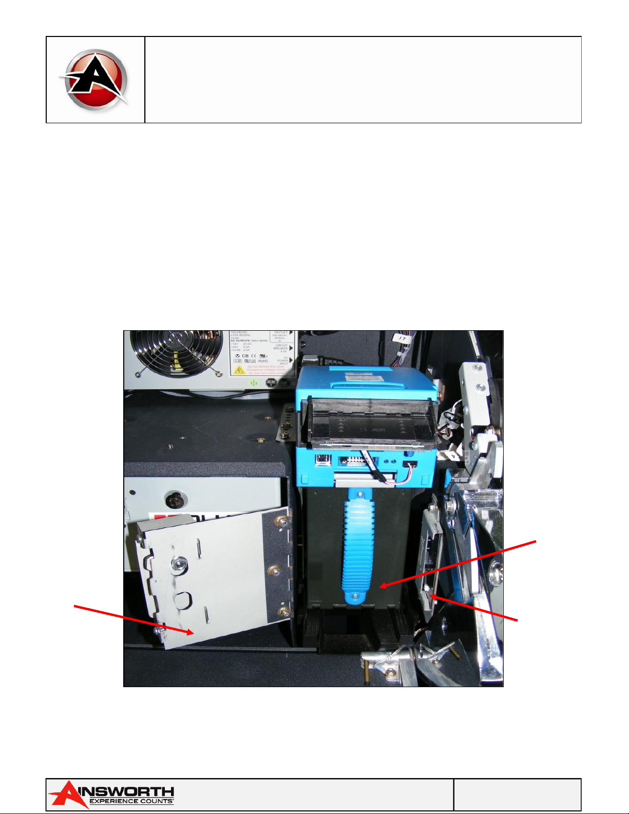
Power Supply Replacement ................................................................................................................................................... 88
Fiber Optic Interface .............................................................................................................................................................. 91
Mainboard Replacement ........................................................................................................................................................ 92
Backplane Board Replacement ............................................................................................................................................. 93
Logic Cage and Backplane Board Replacement ................................................................................................................... 95
RAM Clear ............................................................................................................................................................................... 97
BASE Change ........................................................................................................................................................................ 100
Error Messages .................................................................................................................................................................... 102
Troubleshooting ................................................................................................................................................................... 106
Note Validator Error Display ................................................................................................................................................ 107
Spare Parts List ................................................................................................................................................................... 108
A560X-ST Wagering Terminal Wiring Diagram .................................................................................................................. 118
Appendix A A560X-ST Wagering Terminal badged as A600-ST Wagering Terminal .......................................................... 119
Model Specific changes ....................................................................................................................................................... 119
New Look Terminal .............................................................................................................................................................. 121
Upgraded Features .............................................................................................................................................................. 122

Page 5 of 123
A560
X
-
ST
Service Manual
Pari-Mutuel Wagering Terminal
985 104
-
19 Rev A
Warning:
This machine weighs 130 kilograms.
Exercise extreme care transporting, removing or installing the machine or
personal injury may result.
The venue is responsible for providing a suitable surface to safely mount and
anchor the machine.
During installation, ensure that the machine is securely mounted on so that it
cannot topple when working on the machine.
INTRODUCTION
This Service Manual is intended for use by the appropriate service personnel servicing the approved
Historical Horse Racing Pari-Mutuel Wagering Terminal (Wagering Terminal), which is identified on
the cover page.
Any attempts by other than suitably qualified service personnel to carry out additional servicing may
result in injury to personnel, damage to equipment and voiding of the warranty. Such actions may
also contravene jurisdictional regulations.

Page 6 of 123
A560
X
-
ST
Service Manual
Pari-Mutuel Wagering Terminal
985 104
-
19 Rev A
Chapter 1
Wagering Terminal Physical
Components/Basic Operation

Page 7 of 123
A560
X
-
ST
Service Manual
Pari-Mutuel Wagering Terminal
985 104
-
19 Rev A
Terminal Body Assembly
The Terminal Body Assembly consists of five (5) major assemblies: The Main Terminal Assembly, the
Upper Main Door, the Main Door, the Top Monitor Trim Assembly, and the Pedestal Assembly.
There are two (2) lock assemblies mounted on the right side of the terminal. The front lock (Main
Door Lock) secures the main door assemblies. A large handle on the underside of the lower door
assembly (below the button panel) once depressed opens the lower main door for access to the Bill
Acceptor Cashbox Door. Depressing on the sides of the main door (either side of the LCD) allows
access to the main area. The second lock is a switch (Credit Reset / Audit Mode Switch) that enables
the operator to perform Credit Reset and Audit Mode functions. Items labelled as follows:
Top Monitor Trim
Assembly
Top 27” Non
-
Touch LCD
Player
Tracking
Module
Bottom
24” Touch
LCD
Reset/Audit
Switch
Ticket
Printer
Exit Bezel
Lower access
Panel / Door
Pedestal
Assembly
Main Door
Lock
OLED Button
Panel or LCD
Touchscreen
Note Validator
and Bezel

Page 8 of 123
A560
X
-
ST
Service Manual
Pari-Mutuel Wagering Terminal
985 104
-
19 Rev A
The 24” & 27” LCD Monitor Assemblies
The A560X-ST Wagering Terminal has two (2) LCD Monitor Assemblies; the top LCD comprises of a
Top Monitor Trim Assembly and a frame that includes the 27” LCD Assembly and the monitor control
panel.
The lower LCD comprises of the upper main door assembly which also incorporates a frame that
includes the 24” LCD Assembly and the monitor Control Panel. To access the Monitor Frame and the
Monitor Control Panels on either LCD Assemblies the main door and upper main doors are required
to be open.
Monitor Assemblies
27” LCD
Monitor
Assembly
Top
Monitor
Trim
Assembly
24” LCD
Monitor
Assembly

Page 9 of 123
A560
X
-
ST
Service Manual
Pari-Mutuel Wagering Terminal
985 104
-
19 Rev A
Upper Main Door Assembly
The Upper Main Door is situated at the front of the Terminal Body and includes the bottom 24” LCD
Monitor Assembly, the Note Validator and Ticket Printer Bezels, the Patron Tracking Module opening
(where fitted), a door optic emitter and the speakers.
To open the Upper Main Door; firstly, open the Main Door by rotating the Main Door Lock clockwise
and squeezing the Main Door Release lever located under the button panel assembly.
Once the main door is open push on the main door shroud either side of the LCD to release the upper
main door; the upper main door assembly can then be lifted and opened.
Front of Upper Main Door
Ticket
Printer
Bezel
Note
Validator
Bezel
Speaker
Grills
Player
Tracking
Panel
opening
24” LCD
Monitor
Assembly

Page 10 of 123
A560
X
-
ST
Service Manual
Pari-Mutuel Wagering Terminal
985 104
-
19 Rev A
Underside of the Upper Main Door
Door Optics & Micro Switch
The Door Optics consists of two locations 1. One main door mounted optic and one terminal mounted
optic and 2. One lower main door optic and one terminal mounted optic. With the four installed optics
the Wagering Terminal software can detect if the main door and lower main door is open, closed or
misaligned. There is also a micro switch to ensure the upper main door is latched
correctly.
Speakers
The Speakers are located on the main door assembly and the top LCD surround and a subwoofer is
mounted in the upper terminal. Together they supply sound to the patrons and venue staff alike.
Door
Optic
Emitter
Speakers
Ticket
Printer
Bezel
Note
Validator
Bezel
Player
Tracking
opening
Main Door
Cabinet
Optic
Upper
Main Door
Cabinet
Optic
Door
Latch
Micro
Switch

Page 11 of 123
A560
X
-
ST
Service Manual
Pari-Mutuel Wagering Terminal
985 104
-
19 Rev A
Main Door Assembly
The Main Door is situated below the Upper Main Door and includes the Button Panel, the Main Door
Lock and Audit/Reset Key Assembly and a door optic emitter. The Main Door is also used to access
the BACC Stacker Assembly during cash clearances by venue staff. To open the Main Door; rotate the
Main Door Lock clockwise and squeeze the Main Door Release lever located under the button panel
assembly, indicated as follows:
Main Door
Main Door
Lock
LCD
Touchscreen
Panel
Assembly
Audit / Reset
Key Assembly
Door Optic
Emitter

Page 12 of 123
A560
X
-
ST
Service Manual
Pari-Mutuel Wagering Terminal
985 104
-
19 Rev A
Internal Components
Terminal Internal Components
Logic
Cage
Assembly
Power
Supply
Bill Validator &
Stacker
Assembly
Thermal
Ticket
Printer
Power
Switch
27” LCD
Monitor
Assembly
24” LCD
Monitor
Assembly

Page 13 of 123
A560
X
-
ST
Service Manual
Pari-Mutuel Wagering Terminal
985 104
-
19 Rev A
Note Validator Assembly
Note Validator
Note Validator
The Note Validator receives notes that are entered through the Note Bezel and accepts or rejects
notes by testing them. If the Note Validator rejects a note, the note returns to the patron through the
Note Validator Bezel. If the Note Validator accepts the note, it adds the value of the note in credits to
the Credit Meter, and the note is guided into the Note Stacker for storage.
Note
Validator
Note
Stacker
and
Housing
Note
Validator
Diagnostic
LED’s
Note
Validator
locking
lever
Note Door
Security
Lock
Page 14 of 123
A560
X
-
ST
Service Manual
Pari-Mutuel Wagering Terminal
985 104
-
19 Rev A
Note: The Note Validator Head can be separated on a pivot to provide access to clear minor note jam
clearances.
The Note Validator incorporates an illuminated bezel that indicates to the patron whether the Note
Validator can accept notes and a label showing which denominations. The illuminated bezel
incorporates rows of LED’s which normally illuminate sequentially, indicating that notes may be
entered into the terminal. Constant illumination of a single row of LED’s indicates a Validator fault.
Note Stacker
The Note Stacker provides a secure facility for storing notes (up to 500) accepted by the Note
Validator. After removing the Note Stacker from the terminal, unlock the Note Stacker lock to
remove the notes. The interior of the stacker accommodates a mechanism that retains the notes
under spring tension once they have been inserted.
Note
Stacker
Unit
Note
Stacker
Door Open
Note
Validator
Door Open
Detection
Switch

Page 15 of 123
A560
X
-
ST
Service Manual
Pari-Mutuel Wagering Terminal
985 104
-
19 Rev A
Printer (Optional)
The Printer is an optional device which is fitted to our A560X-ST Wagering Terminal. The Printer is
located beside the Patron Tracking shelf and the tickets exit through the front of the upper main
door.
It is possible to obtain from AGT further assistance regarding the ticket printer in the form of
technical / service manuals on request. Below is the Ithaca 950 one of the many models of printer
used by AGT for our A560X-ST Wagering Terminal’s. *Please Note* the printer can slide forward for
easy paper refill.
Ticket Printer
Ticket
Dispensing
Slot
Paper
Feed and
Status
LEDs

Page 16 of 123
A560
X
-
ST
Service Manual
Pari-Mutuel Wagering Terminal
985 104
-
19 Rev A
Patron Tracking Module Provision
Space is provided between the Note and Printer Bezels on the door for a Patron Tracking Module to
be displayed. The Patron Tracking Components are mounted on a tray assembly between the Ticket
Printer & Note Validator.
Note: To access this space the Upper Main Door assembly must be open.
Logic Cage Assembly
The logic cage is mounted below the patron tracking shelf and is located between the bill acceptor
and ticket printer assemblies. It contains the mainboard assembly that comprise the Wagering
Terminal hardware and software. To access the mainboard assembly:
1. Unlock and slide the security seal latch left to open the logic cage door.
2. The mainboard may then be accessed.
Note: A micro switch on the side of the mainboard assembly enables the terminal to monitor when
the logic cage door opens. An alarm is then activated, and the incident recorded.
Logic Cage
Logic
Cage
Security
Lock
Logic Door
Security
Latch

Page 17 of 123
A560
X
-
ST
Service Manual
Pari-Mutuel Wagering Terminal
985 104
-
19 Rev A
Logic Cage Security Door Open
A560X-ST Wagering Terminal Motherboard Front Panel Layout
Logic
Cage
Security
Switch
Mainboard
Status LEDs
Compact
Flash
Card Slots
Mainboard
Tray
Mainboard
Handle (Pull
to remove
Mainboard)

Page 18 of 123
A560
X
-
ST
Service Manual
Pari-Mutuel Wagering Terminal
985 104
-
19 Rev A
Mainboard Assembly
A560X-ST Wagering Terminal Mainboard Assembly
The major circuit boards within the Logic Cage are:
Mainboard
The main board provides the controlling and operating function of the terminal. The compact flash
cards and system memory are all fitted to the main board and together incorporate the main board
assembly.
Heat Sink and
Fans
Assembly
Mainboard
Status
LEDs
Mainboard
Tray

Page 19 of 123
A560
X
-
ST
Service Manual
Pari-Mutuel Wagering Terminal
985 104
-
19 Rev A
Backplane Board
The Main Board Assembly is connected to the Backplane Board. All peripherals and I/O Devices in
turn are also connected to the Backplane Board. In summary the role of the Backplane Board is to
link the software to all physical devices. Components listed as follows:
Backplane Board inside Logic Cage
Backplane Board below Logic Cage
Mainboard
Connections
Wagering
Terminal
Peripheral
Connections
6 x 12
-
volt
Subsidiary
Power
Connections
LCD Screen
Connection
SAS COMMS
Ports 1, 2 and 3

Page 20 of 123
A560
X
-
ST
Service Manual
Pari-Mutuel Wagering Terminal
985 104
-
19 Rev A
Basic Operation
Power Up
When the terminal has been set up, turn it on using the Wagering Terminal Main Power Switch
located on left hand side of the Logic Cage. When the terminal is switched on it undergoes an
initialization sequence where many testing functions are carried out automatically. If the terminal
passes the Self-Audit Tests during initialization the Game Display Screen will be automatically
displayed after approximately 45 – 60 seconds.
Play Mode
The terminal can be deemed to be in Play Mode when the terminal is turned on (and initialization has
taken place), the Main Door is closed, and locked and no active lockup conditions exist.
Indications that the game is available for play are the illumination of the lamps in the buttons on the
Button Panel to attract patron attention. Other visual indications include “PLAY NOW” being displayed
in the Status Display and the absence of the Message Panel display (which would obscure the game
reels).
Game Display
All game displays are for entertainment purposes only. Actual results are determined by the server
system and jurisdictional requirements.
The A560X-ST Wagering Terminal has a 24” bottom and 27” Top LCD Panel and an optional LCD
topper display.
Table of contents
Other AINSWORTH Arcade Game Machine manuals


Popular Arcade Game Machine manuals by other brands


ELAUT
ELAUT The Big One II manual

Bandai Namco
Bandai Namco Tokyo Revengers Tamagotchi instruction manual

ICE Games
ICE Games Go Ballistic manual

Bob's Space Racers
Bob's Space Racers FEC Whac-A-Mole BSR-3000 Operator instructions

NAMCO
NAMCO PAC-MAN BATTLE ROYALE DELUXE Operation manual

Raw Thrills
Raw Thrills Teenage Mutant Ninja Turtles Operator's manual