AINSWORTH A640 User manual

Pari-Mutuel
Wagering Terminal
Service Manual
985 113 – 25 Rev A

Page 2 of 110
A640
Service Manual
Pari-Mutuel Wagering Terminal
985 113
–
25 Rev A
COPYRIGHT INFORMATION
Ainsworth Game Technology Limited claims copyright on each page of this document.
The right to reproduce, distribute, display and make derivative works from this document, or any
portion thereof requires approval from Ainsworth Game Technology Limited.
For more information please contact:
Ainsworth Game Technology Inc.
5800 Rafael Rivera Way
Las Vegas, Nevada 89118
Ph: (702) 954-3000
Fax: (702) 954-3001
24/7 Customer Service. (855) 241-9061
Email: technicalse[email protected]

Page 3 of 110
A640
Service Manual
Pari-Mutuel Wagering Terminal
985 113
–
25 Rev A
TABLE OF CONTENTS
COPYRIGHT INFORMATION ..................................................................................................................................................... 2
TABLE OF CONTENTS .............................................................................................................................................................. 3
INTRODUCTION ........................................................................................................................................................................ 5
Chapter 1 Wagering Terminal Physical Components/Basic Operation .................................................................................. 6
Cabinet Body Assembly ............................................................................................................................................................ 7
Single 40” Monitor Assembly ................................................................................................................................................... 8
Monitor Controls. ................................................................................................................................................................... 10
Main Door Assembly .............................................................................................................................................................. 11
Button Panel ........................................................................................................................................................................... 12
Door Optics ............................................................................................................................................................................. 12
Speakers ................................................................................................................................................................................. 12
Belly Panel Door Assembly .................................................................................................................................................... 13
Internal Components ............................................................................................................................................................. 15
Note Validator Assembly ........................................................................................................................................................ 16
Note Validator ......................................................................................................................................................................... 16
Note Stacker ........................................................................................................................................................................... 17
Printer (Optional) .................................................................................................................................................................... 18
Player Tracking Module Provision ......................................................................................................................................... 19
Logic Cage Assembly ............................................................................................................................................................. 19
Mainboard Assembly .............................................................................................................................................................. 21
Mainboard ............................................................................................................................................................................... 21
Backplane Board .................................................................................................................................................................... 22
Basic Operation ...................................................................................................................................................................... 23
Power Up ................................................................................................................................................................................ 23
Play Mode ............................................................................................................................................................................... 23
Game Theme Display ............................................................................................................................................................. 23
Specifications ......................................................................................................................................................................... 24
Configuration .......................................................................................................................................................................... 24
Physical ................................................................................................................................................................................... 24
Electrical ................................................................................................................................................................................. 24
Environmental ........................................................................................................................................................................ 25
Standards of Compliance ....................................................................................................................................................... 25
Chapter 2 Wagering Terminal Installation / Conversions .................................................................................................... 26
A640 Wagering Terminal Dimensions ................................................................................................................................... 27
Inspection ............................................................................................................................................................................... 28
Exterior ................................................................................................................................................................................... 28
Interior .................................................................................................................................................................................... 28
A640 Wagering Terminal Mounting Instructions .................................................................................................................. 29
Terminal Installation .............................................................................................................................................................. 31
Chapter 3 Technician Maintenance and Troubleshooting .................................................................................................... 33
System Maintenance / Audit .................................................................................................................................................. 34
Bill Acceptor Validator Test ................................................................................................................................................... 36
Printer Test ............................................................................................................................................................................. 38
Touchscreen Calibration ........................................................................................................................................................ 40
Door Switch Test .................................................................................................................................................................... 42
Terminal SHA-1 Verification .................................................................................................................................................. 43
General Maintenance ............................................................................................................................................................. 45
Cleaning .................................................................................................................................................................................. 45
Note Stacker and Validator .................................................................................................................................................... 45
Note Validator Jam Clearing .................................................................................................................................................. 46
Note Validator Cleaning ......................................................................................................................................................... 48
Circuit Breaker Resetting ...................................................................................................................................................... 48
Monitor Assembly ................................................................................................................................................................... 50
Monitor Door Opening ............................................................................................................................................................ 50

Page 4 of 110
A640
Service Manual
Pari-Mutuel Wagering Terminal
985 113
–
25 Rev A
Monitor Adjustment ................................................................................................................................................................ 52
OSD Menu Screens ................................................................................................................................................................. 53
OSD Control Functions ........................................................................................................................................................... 54
LCD Monitor Replacement ..................................................................................................................................................... 55
Speaker Replacement ............................................................................................................................................................ 60
Subwoofer Replacement ........................................................................................................................................................ 61
Main Door Sub-Assemblies ................................................................................................................................................... 62
Main Door Opening ................................................................................................................................................................. 62
Belly Panel Door Assembly .................................................................................................................................................... 63
LCD Touchscreen with Bash Button Panel Replacement .................................................................................................... 65
LCD Touchscreen with Bash Button Panel Installation........................................................................................................ 67
Changing the Artwork in the Belly Panel .............................................................................................................................. 68
LED Light Panel Replacement ............................................................................................................................................... 69
Internal Components Replacement ...................................................................................................................................... 70
Note Validator Replacement .................................................................................................................................................. 70
Note Validator Housing Replacement ................................................................................................................................... 72
Note Validator Frame Replacement ...................................................................................................................................... 76
Printer Replacement (Optional) ............................................................................................................................................. 77
Player Tracking Module Fitment ........................................................................................................................................... 80
Power Supply Replacement ................................................................................................................................................... 81
To install the Backplane Board: ............................................................................................................................................ 84
Fiber Optic Interface, Optional ............................................................................................................................................... 85
Logic Cage Assembly ............................................................................................................................................................. 86
Mainboard Replacement ........................................................................................................................................................ 86
Backplane Board Replacement ............................................................................................................................................. 87
Logic Cage and Backplane Board Replacement ................................................................................................................... 89
RAM Clear ............................................................................................................................................................................... 91
BASE Change .......................................................................................................................................................................... 94
Error Messages ...................................................................................................................................................................... 96
Troubleshooting ................................................................................................................................................................... 100
Note Validator Error Display ................................................................................................................................................ 101
Spare Parts List .................................................................................................................................................................... 102
A640 Wagering Terminal Wiring Diagram ........................................................................................................................... 110

Page 5 of 110
A640
Service Manual
Pari-Mutuel Wagering Terminal
985 113
–
25 Rev A
INTRODUCTION
This Service Manual is intended for use by the appropriate service personnel servicing the approved
Historical Horse Racing Pari-Mutuel Wagering Terminal (Wagering Terminal), which is identified on
the cover page.
Any attempts by other than suitably qualified service personnel to carry out additional servicing may
result in injury to personnel, damage to equipment and voiding of the warranty. Such actions may also
contravene jurisdictional regulations.
This product complies with CAN ICES-3 (A)/NMB-3 (A)
Warning:
This terminal weighs 123.5 kilograms and is top heavy.
Exercise extreme care transporting, removing or installing the terminal or
personal injury may result.
The venue is responsible for providing a bench of sufficient strength and stability
to safely mount and anchor the terminal.
Ensure that the bench provided can support the weight and will not allow the
terminal to topple if people fall against it.
During installation, ensure that the terminal is securely mounted on its base so
that it cannot topple when routing the wiring in the terminal.
Page 6 of 110
A640
Service Manual
Pari-Mutuel Wagering Terminal
985 113
–
25 Rev A
Chapter 1
Wagering Terminal Physical
Components/Basic Operation

Page 7 of 110
A640
Service Manual
Pari-Mutuel Wagering Terminal
985 113
–
25 Rev A
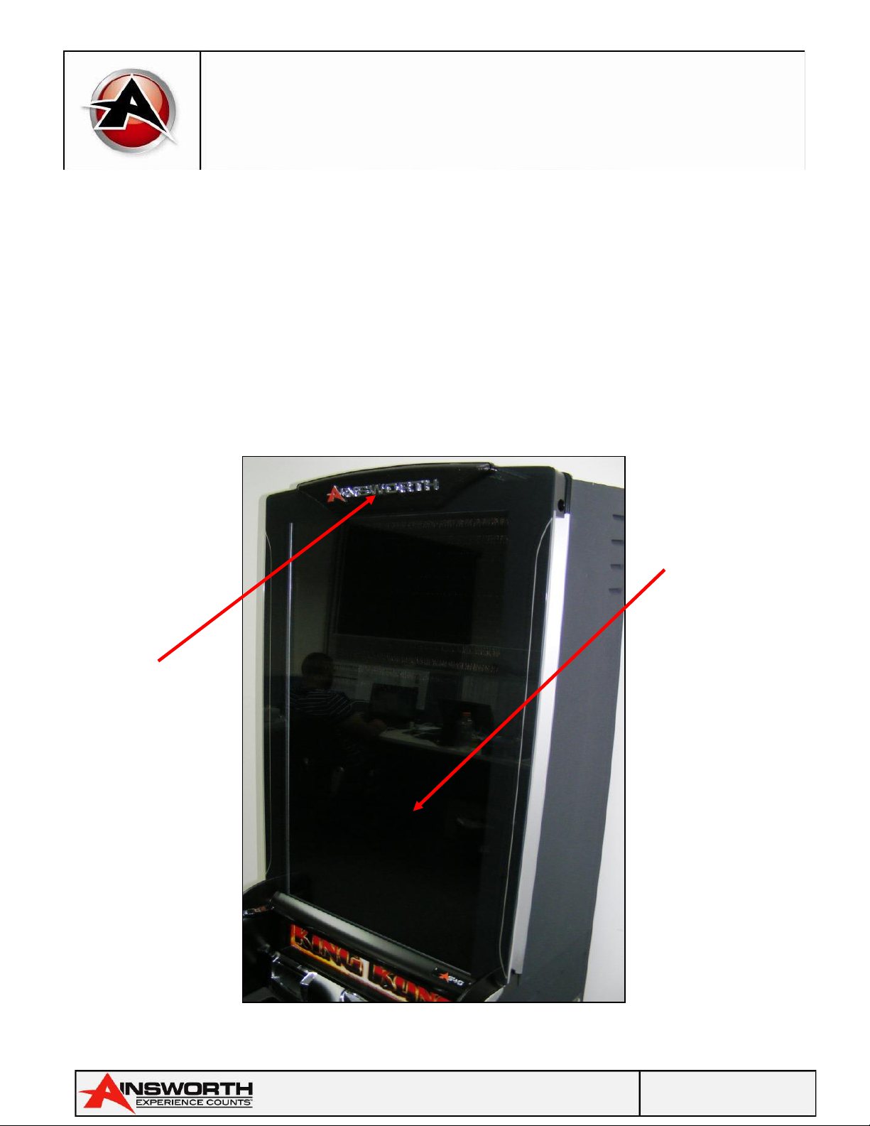
Cabinet Body Assembly
The Cabinet Body Assembly consists of four major assemblies: The Main Cabinet Assembly, the Main
Door, the Belly Door Assembly and the Monitor Door Assembly.
There are three lock assemblies mounted on the right side of the cabinet. The front lock (Belly Door
Lock) secures the Belly Door. A large button and lock at the side of the door assembly once unlocked
and depressed opens the belly door for access to the Bill Acceptor Cashbox Door; the middle door lock
(Main Door Lock) secures the Main Door Locking Bar. A knurled lever (Main Door Release) protruding
from the right side of the terminal below this lock opens the Main Door. The rear lock is a switch (Credit
Reset / Audit Mode Switch) that enables the operator to perform Credit Reset and Audit Mode functions.
Indicators are labelled below:
Single 40”
LCD Monitor
Door
Assembly
Player
Tracking
Module
Reset/Audit
Switch
Ticket
Printer
Exit Point
Belly
Panel
Door and
Artwork
Optional
Chip Tray
Main Door
Lock and
Door
Release
Lever
Note Validator
and Bezel
Belly Door
Release Button
Page 8 of 110
A640
Service Manual
Pari-Mutuel Wagering Terminal
985 113
–
25 Rev A
Single 40” Monitor Assembly
The Main Monitor Assembly is comprised of a combined Monitor Door and 40” LCD Assembly. To
access the LCD Monitor and the Monitor Control Panel it is required to open the combined Monitor
Door Assembly first (labelled below).
Note: The Monitor Door Assembly can only be opened if the Main Door is open.
Open the Main Door by rotating the Main Door Lock clockwise and raising the Main Door Release
knurled lever.
Once the main door is open there is a plastic knob (Monitor Door release) on the R/H side of the bill
acceptor head; lift this to unlock and open the monitor door assembly which is now combined with the
40” LCD Monitor.
Monitor Assembly
Single 40” LCD
Monitor
Assembly
Combined
Monitor
Door
Assembly
Page 9 of 110
A640
Service Manual
Pari-Mutuel Wagering Terminal
985 113
–
25 Rev A
Monitor Door Release
Monitor Door Opened
Lift Knob
to Unlock
Monitor
Door
MEI Bill
Acceptor
Power, USB and
DVI Connections.
Power LED on
Monitor Control
Panel.

Page 10 of 110
A640
Service Manual
Pari-Mutuel Wagering Terminal
985 113
–
25 Rev A
Monitor Controls.
Note: The monitor control panel is located at the rear of the LCD assembly on the bottom left hand
side and has an LED to show power is applied to the monitor.
Monitor Control label
Monitor
Control
Panel
Power LED
(Turned Off)
Page 11 of 110
A640
Service Manual
Pari-Mutuel Wagering Terminal
985 113
–
25 Rev A
Main Door Assembly
The Main Door is situated at the front of the Cabinet Body and includes the Belly Door Assembly, the
optional Coin Validator and Chute Mechanism, the Chip Tray, the Player Tracking Module (where fitted)
and the speakers.
To open the Main Door, rotate the Main Door Lock clockwise and raise the Main Door Release.
Player Tracking
Module / Light
Panel
Assembly
Bill
Acceptor
Bezel
Speakers
Optional
Coin
Diverter
Optional Chip
Tray
Optional Coin
Chute
Assembly
Optional
Coin
Validator
Optional
Coin In
Printer
Bezel
Door Optic
Emitter

Page 12 of 110
A640
Service Manual
Pari-Mutuel Wagering Terminal
985 113
–
25 Rev A
Button Panel
The button panel consists of an LCD touchscreen with one (1) mechanical play button to allow the
patron to interact with the Wagering Terminal. The buttons also allow the operator and service
technician to carry out testing and audit functions on the terminal. The buttons can be replaced
individually, or the buttons may have LED’s or micro switches replaced without the need to replace the
entire button.
Door Optics
The Door Optics consists of one door mounted optic and one cabinet mounted optic; with the two
installed optics the Wagering Terminal software can detect if the main door is open, closed or
misaligned.
Speakers
The Speakers are located on the door assembly and supply sound to the patrons and venue staff alike.

Page 13 of 110
A640
Service Manual
Pari-Mutuel Wagering Terminal
985 113
–
25 Rev A
Belly Panel Door Assembly
The Belly Panel Door is situated at the front of the Main Door and includes the LCD touchscreen with
Bash Button Panel assembly, the Belly Panel Artwork and LED Belly Panel lighting. The Belly Panel
assembly is also used to access the BACC Stacker Assembly during cash clearances by venue staff. To
open the belly door, rotate the belly door lock and press the belly panel door release button, as
indicated below:
Belly Panel Door
Lock
Belly Panel
Door Release
Button
Belly Panel
Door Opening

Page 14 of 110
A640
Service Manual
Pari-Mutuel Wagering Terminal
985 113
–
25 Rev A
Belly Panel Door Assembly (Con’t)
Belly Panel Door Open
Button
Panel and
LED
Backlight
Connector
Harness
Access to
Stacker
Door
through
Belly Panel
Door
Gas strut on
Belly Panel Door
Button Panel or LCD
Touchscreen with
Bash Button
Belly Door
Open
Detection
Switch.
Page 15 of 110
A640
Service Manual
Pari-Mutuel Wagering Terminal
985 113
–
25 Rev A
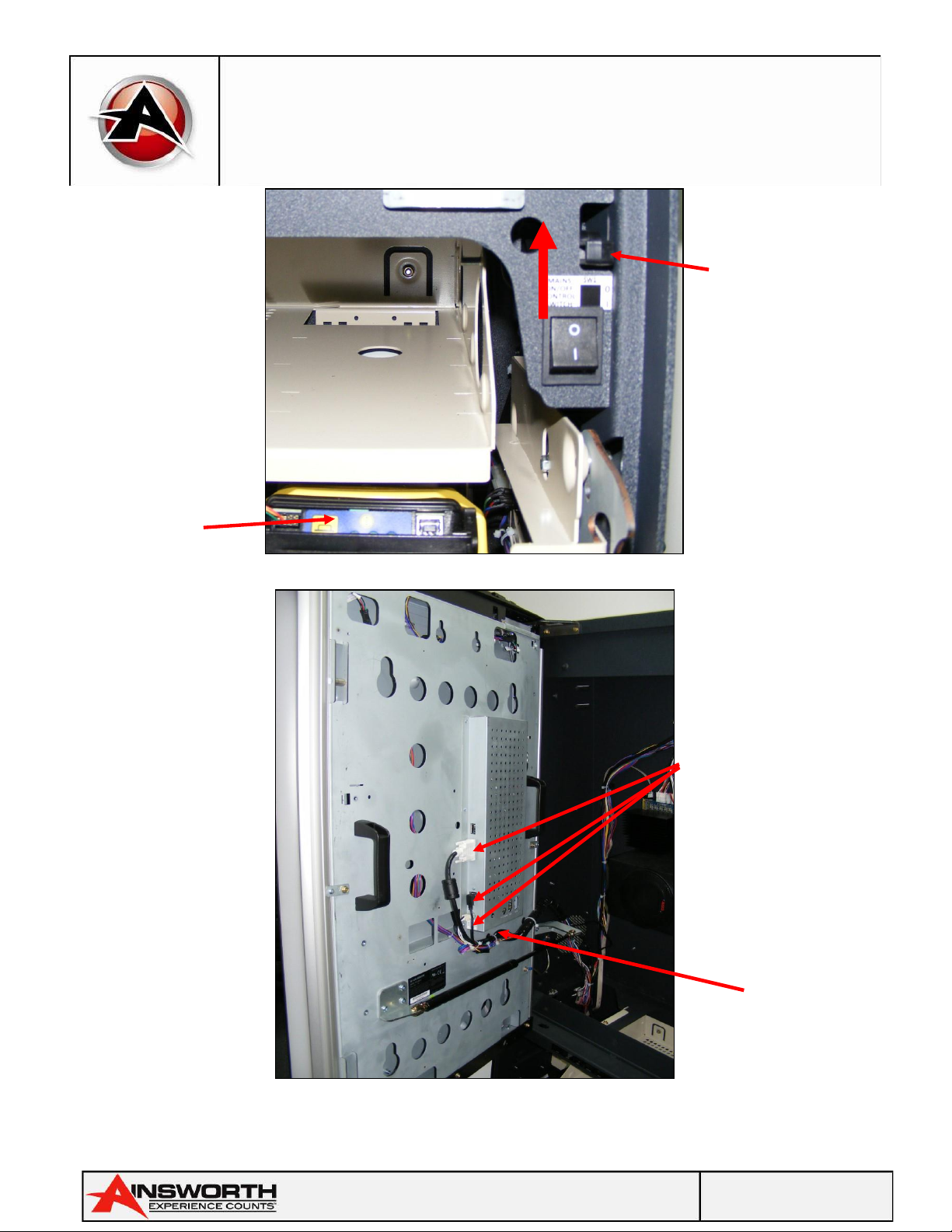
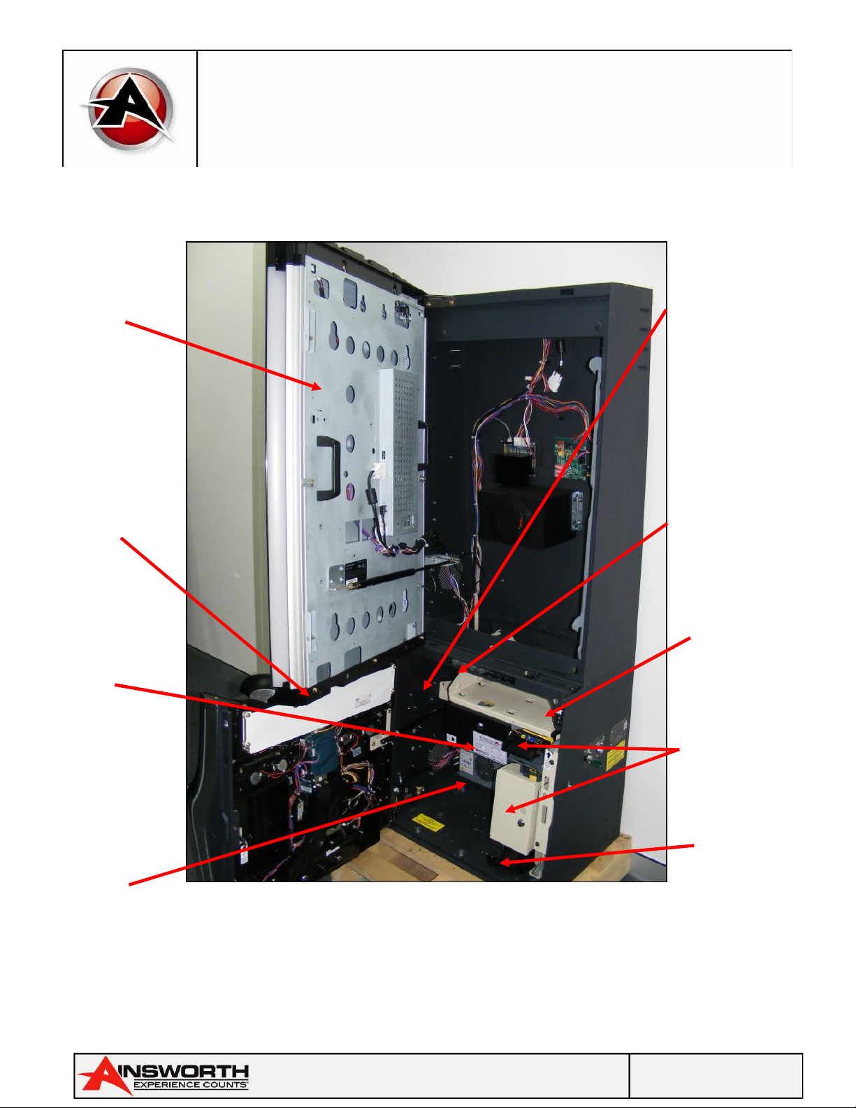
Internal Components
Terminal Internal Components
40” LCD
Monitor Door
Assembly
Hard
Meter
Assembly
Logic
Cage
Assembly
Player
Tracking
Blank /
Light
Panel
Assembly
Power
Supply
Bill Validator &
Stacker
Assembly
Cashbox
Chute
Thermal
Ticket
Printer
location
Power
Switch
Page 16 of 110
A640
Service Manual
Pari-Mutuel Wagering Terminal
985 113
–
25 Rev A
Note Validator Assembly
Note Validator
Note Validator
The Note Validator receives notes that are entered through the Note Bezel and accepts or rejects notes
by testing them. If the Note Validator rejects a note, the note returns to the patron through the Note
Validator Bezel. If the Note Validator accepts the note, the note is guided into the Note Stacker for
storage, the value of the note in credits is added to the Credit Meter.
Note
Validator
Note
Stacker
and
Housing
Note
Validator
Diagnostic
LED’s
Note
Validator
locking
lever
Note Door
Security
Lock.

Page 17 of 110
A640
Service Manual
Pari-Mutuel Wagering Terminal
985 113
–
25 Rev A
Note: The Note Validator Head can be separated on a pivot to provide access to clear minor note jam
clearances.
The Note Validator incorporates an illuminated bezel that indicates to the patron whether the Note
Validator can accept notes and a label showing which denominations. The illuminated bezel
incorporates rows of LED’s which normally illuminate sequentially, indicating that notes may be
entered into the terminal. Constant illumination of a single row of LED’s indicates a Validator fault.
Note Stacker
The Note Stacker provides a secure location for storing notes (up to 500) accepted by the Note
Validator. After removing the Note Stacker from the terminal, unlock the Note Stacker lock to remove
the notes, labelled below. The interior of the stacker accommodates a mechanism that retains the
notes under spring tension once they have been inserted.
Note
Stacker
Unit
Note
Stacker
Door Open
Note
Validator
Door Open
Detection
Switch

Page 18 of 110
A640
Service Manual
Pari-Mutuel Wagering Terminal
985 113
–
25 Rev A
Printer (Optional)
The Printer is an optional device which is fitted to our A640 Wagering Terminal. The Printer is located
beside the Logic Cage and the tickets exit through the top of the main door.
It is possible to obtain from AGT further assistance regarding the ticket printer in the form of technical
/ service manuals on request. Below is the Ithaca 950 one of the many models of printer used by AGT
for our A640 Wagering Terminal’s. *Please Note* the printer can slide forward for easy paper refill.
Ticket Printer
Ticket
Dispensing
Slo.
Page 19 of 110
A640
Service Manual
Pari-Mutuel Wagering Terminal
985 113
–
25 Rev A
Player Tracking Module Provision
Space is provided above the Note and Printer Bezels in the door for a Player Tracking Module to be
fitted. The Player tracking can be mounted on the door or in a tray (preferred).
Note: To access this space the Main Door assembly must be open.
Logic Cage Assembly
The logic cage is mounted below the player tracking shelf and is located between the bill acceptor
and ticket printer assemblies. The logic cage contains the mainboard assembly and houses the
Wagering Terminal hardware and software. To access the mainboard assembly:
1. Unlock and slide the security seal latch left to open the logic cage door.
2. The mainboard may then be accessed.
Note: A micro switch on the side of the mainboard assembly enables the terminal to monitor when the
logic cage door opens. An alarm is then activated, and the incident is recorded..
Synergy XLR Logic Cage
Logic
Cage
Security
Lock
Logic Door
Security
Latch

Page 20 of 110
A640
Service Manual
Pari-Mutuel Wagering Terminal
985 113
–
25 Rev A
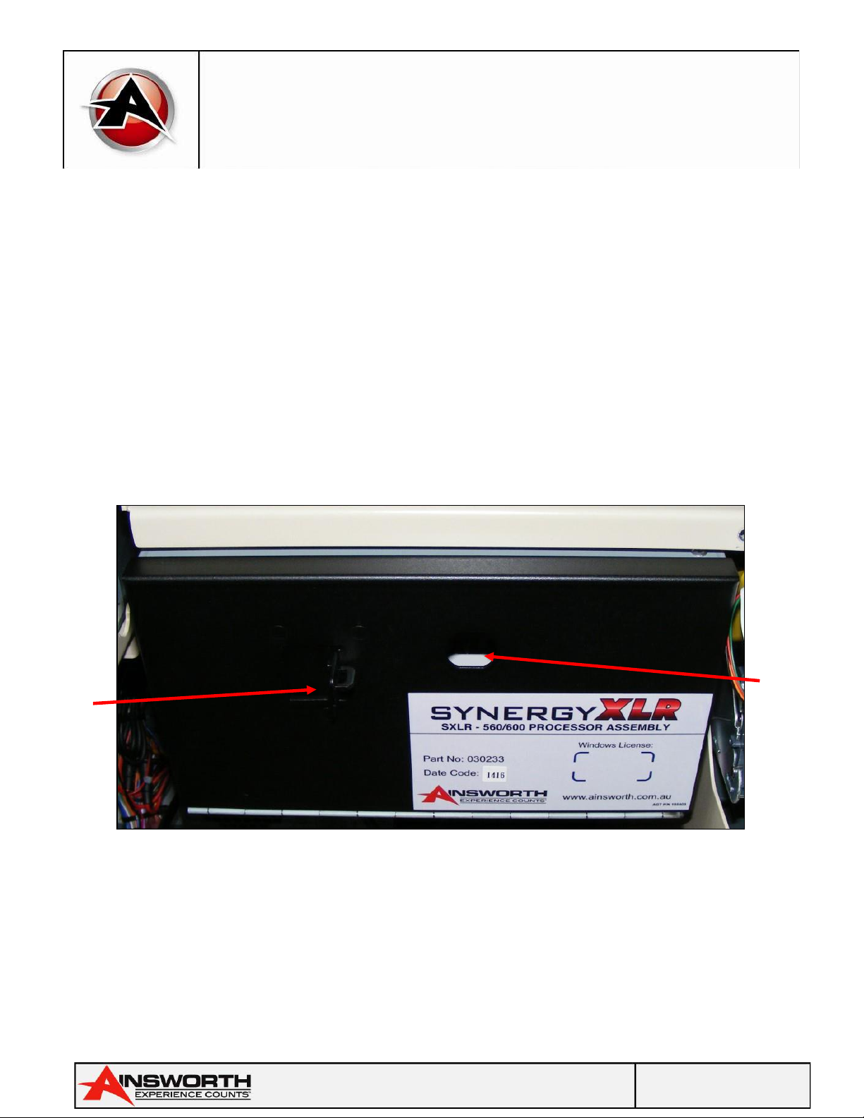
Logic Cage Security Door Open
A640 Wagering Terminal Motherboard Front Panel Layout
Logic
Cage
Security
Switch
Mainboard
Status LEDs
Cast Card
Slots
Mainboard
Tray
Mainboard
Handle
(Pull to
remove
Mainboard
Table of contents
Other AINSWORTH Arcade Game Machine manuals


Popular Arcade Game Machine manuals by other brands

Injoy Motion
Injoy Motion ALLIED TANK ATTACK Setup and service guide

Coleco
Coleco VISION 2413 owner's manual

LEXIBOOK
LEXIBOOK Power Cyber Arcade JL3000 instruction manual

Konami
Konami HELLNIGHT Operator's manual

Sega
Sega HOUSE OF THE DEAD 4 SUPER DELUXE owner's manual

Andamiro
Andamiro DC SUPER HEROES Service manual

Stern Pinball
Stern Pinball IRON MAN Service and operation manual

Arachnid
Arachnid E650FSRT-BK2 instruction manual

Innovative Concepts in Entertainment
Innovative Concepts in Entertainment Monopoly Roll -N- Go Assembly guide

Kriss Sport
Kriss Sport Superpunch BOXER user guide

GCE
GCE Vectrex Blitz! manual

DSM
DSM TIC TAC TOE owner's manual


