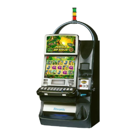
Atronic e2-motion User manual

www.atronic.com
Atronic e²-motion™
Installation Manual
Rev. 1.2
June 2008

2
June 2008
e²-motion™ Installation Manual
RELEASE INFO
Release Info:
Atronic e²-motion™
Installation Manual
Rev. 1.2
June 2008
WARNING!
This manual is intended to provide QUALIFIED TECHNICAL PERSONNEL ONLY with
the information necessary to install the e²-motion™ cabinet and components. To avoid
personal injury or damage to the equipment, do not perform any servicing other than
that contained in this manual.
Copyright Notice:
© 2008, Atronic. All rights reserved.
No part of this publication may be copied or distributed, transmitted, transcribed,
stored in a retrieval system, or translated into any human or computer language, in
any form or by any means, electronic, mechanical, magnetic, manual, or otherwise, or
disclosed to third parties without the express written permission obtained from a
properly authorized official of Atronic.
DISCLAIMER
Atronic makes no representation or warranties, express or implied, with respect to
this publication, or any product of Atronic, including but not limited to warranties of
merchantability or fitness for any particular purpose. Atronic reserves the right to
make changes, enhancements, revisions and alterations of any kind to this publication
or the product(s) it covers without obligation to notify any person, institution or
organization of such changes, enhancements, revisions and alterations.
TRADEMARKS
This document may contain trademarks of Atronic. All other brand and product names
are trademarks or registered trademarks of their respective companies.

3
June 2008
e²-motion™ Installation Manual
Introduction
About this Manual
Scope, Target Audience, Included Software Releases ....
Related Publications ...................................................
Safety Instructions .........................................................
Machine Components .......................................................
Dimensions ......................................................................
Footprint / Drilling Template ...........................................
Technical Data ................................................................
Machine Installation
Overview ..........................................................................
Machine Mounting ............................................................
Topper Mounting ...............................................................
Replace Shipping Locks .....................................................
Prepare Coin Acceptor .......................................................
Prepare Hopper .................................................................
Check Connectors ..............................................................
Check Commboard Settings ................................................
Apply Power ......................................................................
Switch On .........................................................................
Basic Setup (Overview only) ..............................................
Tests ...............................................................................
Technical Support Telephone Numbers ..............................
4
5
7
10
13
14
15
17
18
20
21
21
21
21
22
22
22
23
24
25
CONTENT

4
June 2008
e²-motion™ Installation Manual
ABOUT THIS MANUAL
Scope
This Installation Manual describes how to install an
Atronic e²-motion™ gaming machine.
It describes how to mount the machine to a base
stand and relevant procedures to be carried out before
the machine can be put into operation. Further it
contains important safety instructions, technical data
and cabinet drawings.
Target Audience
We address qualified technical personnel, who are
involved in installation, setup and configuration of
Atronic gaming machines. With this user group we
assume that they are basically familiar with gaming
machines and casino related terminology.
Please read this document and the contained safety
notes carefully before you start machine installation.
Included Software Releases
The installation procedures described in this manual
do not relate to a certain software version.
INTRODUCTION

5
June 2008
e²-motion™ Installation Manual
ABOUT THIS MANUAL
Related Publications
More detailed information about Atronic e²-motion™
gaming machines may be found in the following
publications:
Software Manuals
• Manual HI Software (C4.x.x.x STD)
• Manual HI Software (C5.x.x.x STD)
Operation Manuals
• Manual E2M Operating (C4.x.x.x STD)
• Manual E2M Operating (C5.x.x.x STD)
Spare Parts
• Manual E2M Parts Catalogue.
Linked Gaming Products
• Manual [
product
] - Setup and Configuration
for a particular linked gaming product, such as
Mystery Magic™, Hot Link™, etc.
Peripherals
(Coin- and bill acceptors, hopper, printer, etc.)
• See folder "Peripherals" on the Atronic Service
Manual CD.
Note: All mentioned manuals can be found on a CD-
ROM titled "Atronic Service Manual 2008"
If this manual did not came with this CD-ROM, please
ask Atronic Technical Service for a free copy of the
latest revision.
INTRODUCTION

6
June 2008
e²-motion™ Installation Manual
- blank page -

7
June 2008
e²-motion™ Installation Manual
SAFETY INSTRUCTIONS
SAFETY INSTRUCTIONS
Note!
This installation manual includes only information
relating to the installation of the e²-motion™ cabinet.
For other machine or cabinet types please refer to
the relevant manuals.
Follow the safety precautions below
and on the next page, to ensure safe
installation and operation.
Caution! High Voltage
Power cable must be disconnected from the main
power socket, so that the machine is free from
electrical current. The power switch is intended for
service purposes only.
Caution! Tipping Hazard
The machine must be fastened to an appropriate base,
to prevent tipping over. Use the baseboard supplied
by Atronic for machine mounting.
-> see also page 17-18.
Caution! Moving Parts
Make sure to disconnect the hopper, when working
on it.
Caution!
The machine must not be cleaned using a high
pressure cleaner or a vapor jet and must not be
installed or operated in areas where high pressure
cleaners or vapor jets are used. Use in dry conditions
only.
Continues on next page

8
June 2008
e²-motion™ Installation Manual
SAFETY INSTRUCTIONS
SAFETY INSTRUCTIONS
Further safety precautions during Installation,
Service and Maintenance
• The machine weight is approx. 114kg. Always use
appropiate equipment for transportation.
• Disconnect the power cable from the socket, befo-
re working at the machine.
• The machine may only be installed or operated in
dry conditions and must be connected to a groun-
ded mains power socket.
• Check that all connectors are seated correctly. Fal-
se connections can cause irreparable damage, not
covered by warranty.
• For power cable routing remove the knock-out pla-
te on the appropriate side of the cabinet. Edge-
protection must be mounted once the knock-out
plate has been removed.
• Only qualified service personnel should perform
repairs.
• Electronic assemblies should only be changed with
the power switched off.
• Use only original Atronic parts for replacement.
• Atronic commboard and mainboard
Danger of explosion if battery is incorrectly repla-
ced! Check for correct polarity and replace with
the same or equivalent type only!
• The machine must not be cleaned using a high
pressure cleaner or a vapor jet and must not be
installed or operated in areas where high pressu-
re cleaners or vapor jets are used. Use in dry con-
ditions only.
• Please refer to relevant Atronic service manuals
for further instructions on setup, operation and
maintenance.

9
June 2008
e²-motion™ Installation Manual
- blank page -

10
June 2008
e²-motion™ Installation Manual
MACHINE COMPONENTS
MACHINE COMPONENTS
Topper Arch
Top Glass
Voucher Printer
(optional)
Coin Entry
Service Buttons
Main Door Lock
Jackpot Key Switch
Audit Key Switch
Hopper Drawer Lock
Bill Entry
Hopper Drawer
Type Plate
Coin Bowl Hand Rest
Button Panel
Loudspeakers
Player Tracking
Unit (optional)
Lower/Main Screen
Mechanical Meters
(hidden)
Topper Glass
Framelights
Toplights
(or Blanking Cover)
Toplight
Upper Screen
Handle Receptacle
Topper

11
June 2008
e²-motion™ Installation Manual
MACHINE COMPONENTS
MACHINE COMPONENTS
Logicbox
Voucher Printer
(optional)
Maindoor Switch
Bill Acceptor
- Head
- Stacker
- Cashbox
(behind optional door)
Hopper Drawer
Hopper
Door Motor
Filterboard Signal
Mechanical Meters
Top Glass Lighting
Hopper Drawer Switch
(hidden)
Coin Acceptor
Coin Optics Boards
Service Button
Reset Button
Logicbox Door
Logicbox Lock
Multimedia (MMPC)
Board Cover
Bill Door Switch
Filterboard Power
Top Glass
Release Lever
Button Panel
Release Button
Power Switch

12
June 2008
e²-motion™ Installation Manual
Logicbox Switch
Backplane
Commboard
Mainboard
DVD-ROM Drive
Graphic Card
(VP11)
Release Lever for
Multimediaboard
Cover
Multimediaboard
Multimediaboard
Cover
MACHINE COMPONENTS
Logicbox
MACHINE COMPONENTS

13
June 2008
e²-motion™ Installation Manual
DIMENSIONS
DIMENSIONS
540
632
1705 (mm)
1360
(Playfield in highest position)
550
607
700
360

14
June 2008
e²-motion™ Installation Manual
FOOTPRINT / DRILLING TEMPLATE
Make sure to leave min. 180mm (7.1") distance to the next machine or
a wall on both sides of the cabinet. Do not cover the ventilation slots
at both sides of the cabinet.
50
6060
55
60
50
Baseboard
Cabinet
Footprint
550
Ø10mm
Ø10mm
Backside
105.5
270.5
394
491
541
0
0
50
117.5
157
0
41.5
181
DIMENSIONS

15
June 2008
e²-motion™ Installation Manual
Weight: approx. 114 kg (251 lbs)
Required Voltage: 100V to 240V AC,
50Hz / 60Hz,
use earthed power outlet
rated min. 8A.
Power Consumption: Idle Mode: approx. 200 Watt,
1.8A / 115V
0.9A / 230V
Payout Mode: approx. 300 Watt,
2.6A / 115V
1.3A / 230V
Max. Power: approx. 450 Watt
(Without internal power outlets)
Power Supply
Secondary Voltage: +24V / 5A
+12V / 17A
- 12V / 0.5A
+5V / 20A
+3.3V / 7A
Fuse Power Supply: F 8A / 250V
Fuses Filterboard: F2 (+12 V) = T 6.3A / 250V (UL fuse)
F3 (+24 V) = T 4A / 250V (UL fuse)
Environmental Specifications
Operating Temperature: 0°C - 45°C
(32°F - 113°F)
Operating Humidity: 0% to 85% (non condensing)
TECHNICAL DATA
TECHNICAL DATA

16
June 2008
e²-motion™ Installation Manual
- blank page -

17
June 2008
e²-motion™ Installation Manual
MACHINE INSTALLATION - OVERVIEW
This section should only be carried out by
qualified technical service personnel.
Review the list below and perform as needed.
Explanations are located on the following pages and
in additional manuals.
Inspect machines for transport damage. Any
transport damage should be noted and witnessed
by the freight forwarder. The manufacturer accepts
no responsibility for transport damage.
Check machines for the correct paytable, glasses,
hardware configuration and that software EPROMs
are correctly installed.
Prepare the base by drilling the mounting holes.
Use the Atronic drilling template for proper
mounting hole placement.
Place and mount the machine to the base, using
the Universal Corpus Baseboard (see next page).
Thread the power cable into the base. Do not
connect power to the machine.
Replace shipping locks with casino specific locks.
Install and connect accounting system.
Check that all internal and external connections
are seated correctly.
Prepare coin acceptor and hopper.
Apply power to the machine.
Load paper into the printer.
Execute basic machine setup (Initial Setup)
Configure game.
Test bill and coin handling.
MACHINE INSTALLATION
Note: Depending on machine
configuration or jurisdictional
requirements, additional tasks
may have to be carried out
before the machine can be put
into operation (e.g. acceptance
inspection, logicbox sealing,
etc.).

18
June 2008
e²-motion™ Installation Manual
MACHINE INSTALLATION
Machine Mounting
Caution! Tipping Hazard
Do not operate the machine unless it
has been properly secured to the base.
The machine can tip over, if it is not
properly mounted to a solid base.
1. Use the baseboard, supplied by Atronic, to mark
the holes on the base before drilling. Make sure to
leave min. 180mm (7.1") distance to the next
machine (or a wall) on both sides of the cabinet.
During shipping the baseboard is mounted on the
bottom side of the machine. If the baseboard is
not yet at hand, use the footprint drawing on page
13 instead.
2. Drill four holes 10mm (3/8") for mounting the
baseboard (A).
3. Drill one out of the three 10mm (3/8") holes for the
machine securing bolt (D). It is not important which
one of the 3 holes is used. If the base has braces
or struttings placed below one mounting hole,
simply use another one.
4. Drill or cut out one 55mm (2¼") hole for threading
the mains cable into the base (B) and cut out the
60 x 50 mm coin drop recess (C)
5. Mount the Universal Corpus Baseboard to the base
using 4 mounting bolts and fasten with washer
and wingnuts.
Make sure that the boltheads are completely
lowered into the counterbores of the baseboard.
MACHINE INSTALLATION
A
B
C
D
Universal Corpus Baseboard
50
6060
55
60
50
Baseboard
Cabinet
Footprint
550
Ø10mm
Ø10mm
Backside
105.5
270.5
394
491
541
0
0
50
117.5
157
0
41.5
181
See also page 13 for footprint drawing

19
June 2008
e²-motion™ Installation Manual
MACHINE INSTALLATION
Machine Mounting (continued)
Caution!
The machine weighs approx. 114 kg.
If available, use a lift truck.
Make sure that the mains power cable is
completely inside the cabinet and not
threaded through the lower AC hole, before
sliding the machine onto the baseboard!
Otherwise the cable will be damaged!
6. Before lifting make sure that the mains power ca-
ble is completely inside the machine and that hop-
per drawer and maindoor are closed and locked.
7. Hook the two carry handles into the handle recep-
tacles at both sides of the cabinet.
8. Lift the machine and then slide it onto the moun-
ted baseboard. The cabinet will grasp into the gui-
des of the baseboard.
9. Carefully slide out the hopper drawer and mount
the securing bolt to secure the machine to the
base stand. Fix the securing bolt with washer and
wingnut.
It is not important which of the 3 holes is used, if
at least one securing bolt is mounted. If the base
stand has braces or struttings placed below one
of the mounting holes, simply use another one.
MACHINE INSTALLATION

20
June 2008
e²-motion™ Installation Manual
MACHINE INSTALLATION
Topper Mounting (optional)
The optional machine toppers are delivered seperately.
They have to be mounted and connected.
Note: Toppers with a progressive display use an addi-
tional power supply not described in this manual.
Please refer to the relevant mounting instructions.
1. Connect and mount the toplight to the topper as
illustrated.
To avoid damaging, hold the toplight at its lower
ring, when you screw it into the topper bayonet
catch.
2. Thread the connecting cables and the earthing ca-
ble into the cabinet and position the topper onto
the cabinet.
3. Fix the topper with 4 knurled nuts.
4. Connect the earthing cable to the earthing stud
on the upper right inside the cabinet. Make sure
that the earthing has good contact and fix it with
a nut with lockwasher.
5. Connect the topper cable labled 65049935 to the
filterboard signal, connector P14.
6. Connect the topper cable labled 65049939 to the
filterboard signal, connector P6.
MACHINE INSTALLATION
Hold here
P14
P6
Table of contents
Other Atronic Arcade Game Machine manuals

Atronic
Atronic Cashline User manual

Atronic
Atronic Harmony Upright User manual

Atronic
Atronic e-motion User manual

Atronic
Atronic Slant Top User manual

Atronic
Atronic e-motion User manual

Atronic
Atronic Cashline User manual

Atronic
Atronic e-motion User manual
Atronic
Atronic Harmony Slant Top User manual
Atronic
Atronic Harmony Upright User manual

Atronic
Atronic Harmony Upright User manual