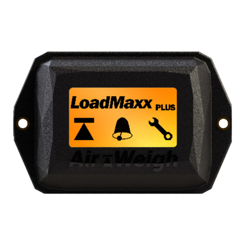
Air Weigh LOADMAXX Operating and maintenance instructions

1
PN 901-0167-000 R0
Air-Weigh Customer Support: 888-459-3247
LoadMaxx
Installation Guide
Full and Dual Trailer Scale

2
Table of Contents
About LoadMaxx Full and Dual Trailer Scales.............................1
Installation Overview.....................................................................1
Tools Required...............................................................................1
Mounting the Scale..........................................................................2
Mounting Flush to the Trailer.......................................................3
Mounting with a Van Bracket.......................................................4
Mounting with a Frame Rail Bracket..........................................5
Connecting Power to the Scale......................................................6
Connecting Power with the ABS Connector.............................6
Connecting Power to the Junction Box.....................................7
LoadMaxx Power and ComLink Cable Installation Guide..........8
Installing the Air Sensors...............................................................9
Routing Cables...............................................................................11
Routing Sensor Cables for Dual HCVs....................................11
Routing Sensor Cables for a Full Trailer..................................12
Checking for Correct Installation.................................................13
Limited Warranty............................................................................14
Procedure for Warranty Claims....................................................15
Notes................................................................................................16

1
About LoadMaxx Full and Dual Trailer
Scales
Installation Overview
will install:
•
• Power interface and extension cables
• Sensor interface and extension cables
• Bracket
•
Tools Required
You will need the following tools to install the trailer scale and air
sensors:
•
•
• Flush wire cutter
•
•
•
• Flat-blade screwdriver

2
Mounting the Scale
• Flush mounted to the trailer frame itself
• Using a van bracket
• Using a frame rail bracket
enclosures.
Note: Do not place strain on the wires. If there is a sharp bend in the
wires, the environmental seal could fail, allowing water to damage
the scale. If the scale is disconnected from the trailer, the power
cable in Port A and/or the sensor cable in Port B will not support the
scale weight.

3
Mounting Flush to the Trailer
1. Determine the best location to mount the scale. This should
the back side of the location is free of obstacles and debris
that would interfere with the installation.
either choose to mount the scale low enough so that the
(Air-Weigh
recommends this option, if possible), or drill a hole large
3. Mark the trailer surface that touches each of the screw holes
4. Drill two 1/4-inch holes into the surface of the trailer where
and 7.
7. Plug the sensor interface cable into Port B at back of scale.
and washers to secure the scale to the side of the trailer.

4
Van Mounting Bracket
installation.
1. Determine the best location to mount the scale. The bracket
screws should be mounted on a ledge, and the scale itself
should hang off the ledge with no obstacles blocking it.
3. Using the marked areas as a guide, drill two 1/4-inch holes
into the surface of the trailer.
4. Secure the scale to the bracket. Insert one bolt and washer
through each of the holes in the trailer casing and tighten.
7. Plug the sensor interface cable into Port B at back of scale.
nuts.
Mounting with a Van Bracket

5
1. Determine the best location to mount the scale on the frame
surface of the frame rail that is visible through the four holes
3. Using the marked areas as a guide, drill four 1/4-inch holes
into the surface of the frame rail.
4. Secure the scale to the bracket. Insert one bolt and washer
through each of the holes in the trailer casing and tighten.
7. Plug the sensor interface cable into Port B at back of scale.
each bracket hole and then insert those bolts through the
nuts.
Frame Rail Mounting Bracket
Mounting With a Frame Rail Bracket

6
Connecting Power to the Scale
Connecting Power with the ABS Connector
North American trailer manufacturers use one of two standard
trailer uses.
1.
breakout connection.
2.
3.
ends of the ABS harness breakout. Make sure the locking
4.
5.

7
route along an existing wiring harness. If the trailer has a
must use an existing wiring harness
or umbilical to avoid damaging or breaking the cable.
6.
7.
on the interface cable. Make sure the cable is under no strain
and is not bent.
Connecting Power to the Junction Box
1.
box. Trace the trailer wiring harness to where it connects to a
2.
trailer toward the location where the scale is installed. If
must use an existing wiring
harness or umbilical to avoid damaging or breaking the cable.
interface cable. Make sure the cable is under no strain and is
not bent.

8
LoadMaxx Power and ComLink Cable Installation Guide
ABS JUNCTION BOX COMLINK

9
Installing Air Sensors
Note: Avoid dropping sensors. Dropping can cause the sensors to
fail immediately or shorten their lifespan.
Note: This process will be repeated for both air sensors.
1.
Full and dual trailers require two air sensors to be installed,
2.
the air bag. The air sensor will be installed here.

10

11
Routing Cables
Routing Sensor Cables for Dual HCVs
1.
2. Route the two cables along the axle and the frame of the
connectors on the interface cable. Make sure all cables are
under no strain and are not bent.

12
Routing Sensor Cables for a Full Trailer
1.
2. Route the two cables along the axle and the frame of the
3.
4.
connectors on the interface cable. Connect the sensor cable
for the front
the rear
5.

13
Checking for Correct Installation
using the scale. You should see 2 sensors in your A/D readings
in Scale Diagnostics. If not, navigate through the setup
wizard. See your user guide for step by step instructions.
1.
2. Select the image of a medical bag to go to Scale
Diagnostics.
3.
readings. The screen should read “EXT A and EXT B” and
show a number for each.
4.
5.
6.
7. Check the height control valve to see if it is loose or broken,
which can cause inaccurate weight readings.
A/D Reading

14
Limited Warranty
Some states do not allow the exclusion or limitation of incidental or consequential

15
Procedure For Warranty Claims
Air-Weigh
issued to the Air-Weigh customer.

16
Notes

17
Notes

18
www.Air-Weigh.com
Other manuals for LOADMAXX
4
Table of contents
Other Air Weigh Scale manuals

Air Weigh
Air Weigh BinMaxx User manual

Air Weigh
Air Weigh LOADMAXX User manual

Air Weigh
Air Weigh LoadMaxx 5809 User manual

Air Weigh
Air Weigh BinMaxx User manual

Air Weigh
Air Weigh QuickLoad User manual

Air Weigh
Air Weigh BinMaxx User manual

Air Weigh
Air Weigh LoadMaxx Plus User manual

Air Weigh
Air Weigh LoadMax User manual

Air Weigh
Air Weigh LOADMAXX User manual