Air Weigh QuickLoad User manual

5
PN 901-0123-000 R6
Air-Weigh Customer Support: 888-459-3247
QuickLoad
Installation Guide
Trucks and Tractors with
Air Pressure Drive

2
TABLE OF CONTENTS
I. SCALE OVERVIEW....................................................................4
1. QuickLoad Tractor Scale Overview................................5
2. Installation Overview for QuickLoad Scale System.........7
A. Overview for Electronic Components Installation ........7
B. Overview for Air Pressure Sensor(s) Installation.........7
C. Overview for Deflection Sensor(s) Installation ............8
II. QUICKLOAD PARTS PER VEHICLE TYPE ...............................9
III. TOOLS REQUIRED (CUSTOMER SUPPLIED).........................11
1. Tools for Air Pressure Sensor(s) installation ................11
2. Tools for Deflection Sensor Installation........................11
IV. INSTALLING THE QUICKLOAD SCALE..................................12
1. Installing the QuickLoad Display..................................12
A. Preparing the QuickLoad Display for Installation.......12
B. Mounting the QuickLoad Display..............................12
2. Connecting the QuickLoad Wiring Harness..................13
A. Connecting the QuickLoad to Power ........................13
B. Connecting the QuickLoad to Sensors and Alarms ...14
B. Secure Cables and Reassemble the Dash ...............14
3. QuickLoad Connection Diagrams ................................15
V. INSTALLING AIR SUSPENSION SENSOR(S) .........................19
1. Air Line Installation for each leveling valve...................19
A. Route Air Line from Air Suspension .........................19
B. Routing Air line for Dedicated Tractor / Trailer Scale 20
2. Installing Sensor(s).....................................................23
A. Installing Air Pressure Sensor (s).............................23
B. Installing Scales with a Steer Axle Deflection Sensor 25
C. Parts and Sensor Configuration Tables....................26

3
3. Setting the QuickLoad’s Sensor Configuration .............31
A. Front Panel Buttons.................................................31
B. Entering the Sensor Configuration ...........................32
VI. FOR FURTHER INFORMATION...............................................33
LIMITED WARRANTY......................................................................34

4
I. SCALE OVERVIEW
The Air-Weigh®QuickLoad Scale™for trucks and tractors with
AP (Air Pressure) drive suspension includes a dashboard-
mounted a QuickLoad display, power harness, sensor cable(s),
and sensor(s) with mounting hardware.
This Installation Guide (p/n: 901-0123-000) gives instructions
for scale installations on vehicles having air or spring drive
suspensions, possibly in combination with air or spring steer
suspensions. It also includes dedicated tractor and trailer
configurations. See Table 7. Kit Configuration Sensor
Assignment for more detail on the various vehicle
configurations.
Follow Air-Weigh’s installation procedures exactly for the most
accurate weighing.
The User Guide (p/n: 901-0124-000), included also with the
scale, provides the complete scale calibration and operation
procedures. These procedures include, among others, the
steps for setting up the scale for your specific sensor
configuration.
Table 1. Specifications
QuickLoad Scale
Diameter: 2.43 inches (61.7 mm)
Height: 3.10 inches (78.7 mm)
Weight: 4.7 oz. (133 g)
Operating Temperature Range:
-4to 158F (-20to 70C)
Input voltage: 9.5V DC to 32V DC
Alarm Output Circuit Limit: 1.0 amps
Weigh Reading
Accuracy
Axle with Air Sensor: ±300 lbs (140 kgs) per
axle group
Axle with Deflection Sensor: ±2% maximum
axle group weight

5
Following installation, you must calibrate the
scale before you can use it to determine axle
group and vehicle weight. For instructions on
calibration, please consult p/n 901-0124-000,
QuickLoad Calibration and Operations Manual.
1. QuickLoad Tractor Scale Overview
The QuickLoad scale converts tractor and trailer suspension
loads to an accurate on-ground weight by comparing empty and
loaded axle group weights with empty and loaded sensor
output. Once calibrated, the scale displays accurate weights for
any air suspension load.
The scale displays the actual on-ground weight of each axle
group to within 300 pounds (140 kilograms) for air suspensions,
or ±2% of maximum axle group weight for spring suspensions.
An axle group is defined by the Height Control Valve(s) (HCV),
or leveling valve(s), on the air suspension, or as the set of
axles supporting a spring suspension. For instance, a tandem
drive axle suspension typically has only one HCV. The two
drive axles make up a single group and the displayed weight
will be for the total tandem weight.
The QuickLoad scale can display up to four axle groups on one
tractor/trailer combination. Once the QuickLoad is calibrated for
weight, it is not necessary to recalibrate unless the suspension
characteristics change.

6
Figure 1. Air Pressure Drive Sensor Hookup
Figure 2. Deflection Sensor Drive Sensor Hookup
Legend:

7
Ensure that each sensor’s electrical cable is
connected to the correct QuickLoad port. For a
list of the correct port for each sensor, see Table
7, page 22.
2. Installation Overview for QuickLoad Scale System
This guide will give all necessary details of the following steps
for installing the QuickLoad Scale System.
A. Overview for Electronic Components Installation
Cut hole in dash for display; mount QuickLoad to dash.
–OR –
Mount QuickLoad in pod on top of dash, using the
optional pod mounting kit, P/N: 1225.
B. Overview for Air Pressure Sensor(s) Installation
For air suspension scales with air bag(s) on the drive
suspension, install air pressure sensor(s) under dash.
Route air line(s) from drive suspension to sensor(s)
installed under dash.
For scales which calculate the weight at the steer axle
from the drive axle suspension (configurations 5800,
5801, 5841, 5845, 5851, 5855, 5860), no steer axle
sensor is needed.
Air lines and cables to the sensor, and any other
Air-Weigh wiring, must be separated by a
minimum of 12 inches, or properly shielded, from
exhaust piping.

8
For scales where the steer axle weight is intentionally
not displayed (configurations 5803, 5809, 5810, 5816,
5840, 5844, 5850, 5854), no steer axle sensor is
needed.
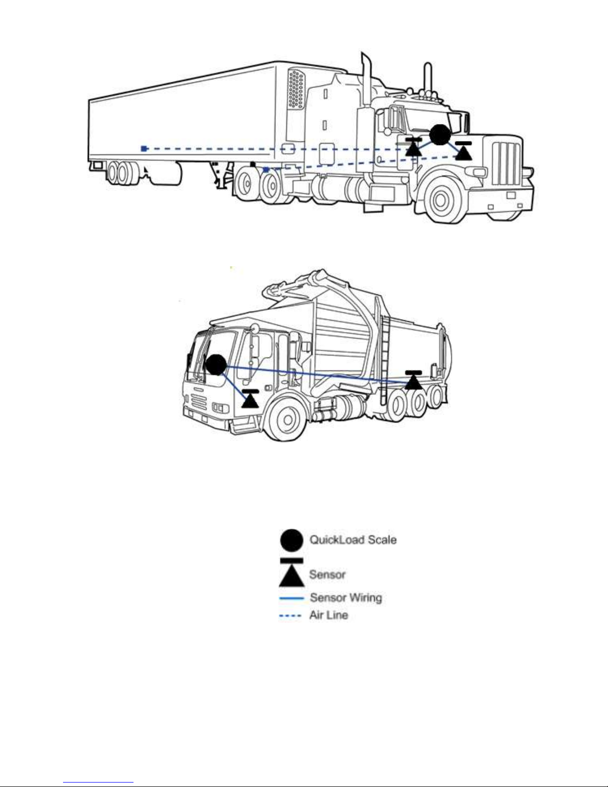
For scales with a steer axle with air suspension
(configurations 5805, 5806, 5815, 5821, 5826, 5827,
5838, 5842, 5847, 5852, 5856), route air line(s) from
steer axle suspension to sensor(s) installed under dash.
For scales which determine the weight at the lift axle
(configurations 5833 –5836, 5838, 5839 and 5864),
refer to p/n 901-0117-000, Application Note,
LoadMaxx, Installing and Calibrating the Lift Axle, for
lift axle sensor installation instructions.
For Dedicated Tractor/Trailer Scales (configurations
5840 –5857 except 5849), route trailer suspension air
line(s) to sensor(s) installed under dash.
C. Overview for Deflection Sensor(s) Installation
For scales that include steer axle deflection sensors
(configurations 5807, 5808, 5814, 5817, 5820, 5822,
5823, 5825, 5828, 5829, 5831, 5833, 5834, 5835, 5836,
5839, 5843, 5846, 5853, 5857 and 5864), refer to p/n
901-0059-000, Steer Axle Deflection Sensor Kit
Installation Guide, for installation instructions.
For scales that include dual drive axle deflection sensors
on Hendrickson™ HaulMaxx or HN 462/463
suspensions (configurations 5810, 5814, 5818, 5824,
5829 or 5833), refer to p/n 901-0092-000, Drive Axle
Dual Deflection Sensor Installation Guide.
For scales that include a single drive axle deflection
sensor (configurations 5807, 5708, 5817, 5833 –5836,
5839, 5843, 5853), contact Air-Weigh.

9
II. QUICKLOAD PARTS PER VEHICLE TYPE
The most popular QuickLoad parts are shown in Table 2, below.
See Table 6 for a comprehensive listing of all QuickLoad parts.
The Air Line and Disconnect kits in Table 2 are optional. They
are needed only if the vehicle does not already have those air
lines and disconnects, bringing air pressure from the air
suspension to behind the dash, already in place.
Table 2: QuickLoad Part Numbers
Part Number
Description
1350
QuickLoad Display Kit which includes the display,
mounting hardware, power cable, and user manual.
1360
QuickLoad Air Sensor Kit which includes a single air
pressure sensor, push-in fittings, and a 3' cable.
1361
QuickLoad Air Sensor Kit which includes dual air
pressure sensors, push-in fittings, two 3' cables and a
Y Cable. For 3-sensor and 4-sensor systems only.
1380
QuickLoad Alarm Kit.
1390
Deflection Sensor Kit which includes 15’ sensor
cable, mounting brackets, and installation manual.
010-0023-000
Air Line Kit (optional)
010-0028-002
Trailer Disconnect Kit (optional)
010-0029-002
Two Trailer Disconnect Kit (optional)

10
QuickLoad parts per vehicle type, for the most popular
software configurations, are shown in Table 3, following. See
Table 7 for a comprehensive listing of QuickLoad parts for all
vehicle types.
All configurations require P/N 1350, QuickLoad Display
Kit, which is not otherwise shown in the following table.
Table 3: QuickLoad Parts for the Most Popular Vehicle
Configurations
Vehicle
Description
Drive
Suspension
Steer
Trailer
Suspension
Parts
Needed
Software
Config
Tractor
Air-Ride
Single HCV
Leaf Spring,
Calculated to
1%
Not Included
1 ea. 1360
5800
Tractor
Air-Ride
Dual HCV
Leaf Spring,
Calculated to
1%
Not Included
2 ea. 1360
5801
Truck
Air-Ride
Single HCV
Leaf Spring,
Not Displayed
Not Included
1 ea. 1360
5803
Tractor
Air-Ride
Single HCV
Air-Ride
Single HCV
Not Included
2 ea. 1360
5805
Truck
Air-Ride
Single HCV
Leaf Spring,
Deflection
Sensor
Not Included
1 ea. 1360
1 ea. 1390
5807
Dedicated
Tractor Trailer
Air-Ride
Single HCV
Leaf Spring,
Not Displayed
Air-Ride
Single HCV
2 ea. 1360
5850
Dedicated
Tractor Trailer
Air-Ride
Single HCV
Leaf Spring,
Calculated to
1%
Air-Ride
Single HCV
2 ea. 1360
5851

11
III. TOOLS REQUIRED (CUSTOMER SUPPLIED)
1. Tools for Air Pressure Sensor(s) installation
Screwdrivers –flathead and/or Philips
Assorted wrenches
Drill
2 1/8” hole saw
Optional ¾” hole saw for running air line to dash
Safety glasses
Wire cutter
Crimper
Teflon™ pipe thread tape
2. Tools for Deflection Sensor Installation
Sander with 40-grit medium
Chalk or permanent marker
Flat blade screwdriver
9/16-inch combination wrench
Torque wrench, 20 –80 ft-lb
9/16-inch deep well socket with ⅜-inch socket handle
½-inch to ⅜-inch socket adapter
Optional:
Deflection Sensor Field Test Set
The Deflection Sensor Install Field Test Set, p/n 1000,
can measure raw deflection sensor readings without the
sensor’s connection to the QuickLoad Scale.
For installation of the steer axle deflection sensor,
refer to p/n 901-0059-000, Steer Axle Deflection
Sensor Kit Installation Guide, which is included in
kits 1390 and 1391.

12
For installation of the Hendrickson Walking Beam
drive axle deflection sensors, refer to p/n 901-0092-
000, Steer Axle Deflection Sensor Kit Installation
Guide, which is included in kit 1392.
IV. INSTALLING THE QUICKLOAD SCALE
The installation of an Air-Weigh QuickLoad Scale on a vehicle
includes mounting two major classes of components:
Electronics components: QuickLoad display and power
interface cable
Sensor(s) and sensor cable(s)
1. Installing the QuickLoad Display
A. Preparing the QuickLoad Display for Installation
Numbers called out in refer to Figure 3 unless
otherwise stated.
1. Select a location for the display (1) on the dash
panel (5) with at least 3-inch clearance behind the
dash panel for the unit and its connections. A higher
dash position provides better visibility.
2. Cut a 2⅛-inch hole (2) in the dash at that location.
3. Remove the hex nuts (4) from the studs (6) on the
back of the display (1) to release the mounting
bracket (3).
B. Mounting the QuickLoad Display
1. Position the display (1) in the hole (2) so that it
appears level on the dash, as shown in Figure 3.
2. Reinstall the mounting bracket (3) on the back of the
display and secure with two nuts (4) on the display
studs (6). Tighten the nuts and secure the display to
the dash using 6 ft-lbs. of torque. Do not over
tighten the mounting bracket nuts.

13
Figure 3. Installing the Display
2. Connecting the QuickLoad Wiring Harness
A. Connecting the QuickLoad to Power
The QuickLoad power wiring harness, p/n
012-0600-008, connects the QuickLoad scale to the
vehicle’s power and ground circuits. Consult Table 4.
Table 4. Wiring Harness Hookup
Power and Ground Table
White wire
Vehicle chassis ground
Blue/Black wire with
in-line fuse
12VDC or 24VDC ignition hot
power
1. Connect the white wire to chassis ground.
2. Connect blue/black wire with inline fuse to the
positive (+) or “hot” side of the 12 VDC or 24 VDC
ignition power source. DO NOT connect directly
to battery.
1
23
4
5
6AW0099-1006

14
B. Connecting the QuickLoad to Sensors and Alarms
1. Connect the 4-pin sensor cable(s) to the QuickLoad
Sensor Inputs A, B, or C/D, as indicated in the
Sensor Connection figures, pages 15-17.
2. To connect an external alarm using the QuickLoad
Alarm Kit (p/n 1380), consult the QuickLoad Alarm
Kit Manual, included in the Alarm Kit.
a) Connect the 4-pin sensor cable with alarm lead
to the QuickLoad Sensor Input specified in the
Sensor Connection figures, pages 15-17.
b) Connect the sensor cable alarm lead to the end
of the alarm cable.
c) Connect the alarm (or alarm light) power wire to
a 12V/ 24V ignition hot source.
3. Turn on key for system self-test. If system does not
successfully complete the self-test, see
Troubleshooting Section at the end of this manual.
B. Secure Cables and Reassemble the Dash
1. Coil excess wires and harnesses and secure using
nylon cable ties.
2. Tie wires and sensor assemblies to other secured
harnesses, to prevent damage due to vibration.
3. Reassemble the dash assembly. Ensure all
connections are tight.
4. Turn the ignition key ON and perform a final
system check.

15
PWR – Power
connection
A – Port for
sensor and
1st alarm
connection
B – Port for
sensor and
2nd alarm
connection
C/D – Port for
single or dual
sensor
connection
PWR – Power
connection
A – Port for
sensor
connection
(Optional: 1st
alarm
connection)
3. QuickLoad Connection Diagrams
Please reference Table 7. Kit Configuration Sensor
Assignment, for the sensor configuration required for your
installation. The following figures give a view of the connectors
on the back face of the QuickLoad Scale. They show where the
ports for the different configurations mentioned in Table 7 are
located.
Figure 4. QuickLoad sensor and alarm ports
Figure 5. Connections for single sensor system

16
Figure 6. Connections for a two sensor system
PWR – Power
connection A – Port for
sensor
connection
(Optional: 1st
alarm
connection)
B – Port for
sensor
connection
(Optional:
2nd alarm
connection)
PWR – Power
connection A – Port for
sensor
connection
(Optional: 1st
alarm
connection)
B – Port for
sensor
connection
(Optional:
2nd alarm
connection)
C – Port for
sensor
connection
Figure 7. Connections for most three sensor
systems (excludes 5821 and 5828)

17
Figure 8. Connections for configurations
5821 and 5828
Figure 9. Connections for four sensor system
PWR – Power
connection
A – Port for
sensor
connection
(Optional: 1st
alarm
connection)
C/D – Port for
dual sensor
connection
PWR – Power
connection
C/D – Port for
two single or
one dual
sensor
connection
A – Port for
sensor
connection
(Optional: 1st
alarm
connection)
B – Port for
sensor
connection
(Optional:
2nd alarm
connection)

18
The scale will only display accurate weights after it
has been completely calibrated to a certified platform
scale, by entering empty and loaded axle weights into
the Air-Weigh Scale. Enter empty weights only when
the vehicle is empty! Enter loaded weights only
when the vehicle is loaded!
See QuickLoad Calibration and Operations Manual,
p/n 901-0124-000, for complete instructions.

19
V. INSTALLING AIR SUSPENSION SENSOR(S)
1. Air Line Installation for each leveling valve
A. Route Air Line from Air Suspension
Follow the same instructions for air line and
sensor installation for both drive and steer air
suspensions. The parts in this section’s instructions
are listed in Table 5.
If an Air Suspension Gauge for the suspension
already exists in dash, skip to V.2, Installing
Sensor(s).Otherwise, continue with this procedure.
1. Route a ¼-inch air line from the airbag suspension
to the dash.
Figure 10. Airbag and Air Line Connections
2. Use a ¼-inch straight street-T at the top of a
convenient drive axle suspension air bag to access
Air Supply Line
for Airbag
T-fittings
Air Line
to Sensor
Additional
Air Line
Airbag

20
air pressure. If you choose to connect in the
middle of an existing air line between two air bags,
thoroughly remove any paint on the air line and
wipe clean before cutting the air line.
3. Route the air line along with other air lines and
cables into the dash. Loosely connect the air line
to the other air lines and cable with cable ties to
prevent it from being damaged.
B. Routing Air line for Dedicated Tractor / Trailer Scale
The parts in this section’s instructions are listed in
Table 5. If Trailer Suspension gauge already exists in
dash, skip to V.2, Installing Sensor(s).
Table 5. Air Line and Disconnect Kit BOMs
Bill of Materials for Suspension Air Line Kit, p/n 010-0023-000
PART NUMBER
DESCRIPTION
QTY
145-4552-001
NYLON TIE, 7", T-50, NYLON, BLK
25
150-4081-000
¼ NPT STREET TEE, DOT, BRASS
1
150-4083-000
DOT COMPRESSION, ¼ NPT, MALE,BRASS
1
380-0046-000
40' X ¼” SAE J844 DOT TUBING
1
BOM for Trailer-Direct Disconnect Kit, p/n 010-0028-002
145-4552-001
NYLON TIE, 7", T-50, NYLON, BLK
25
150-4081-000
¼ NPT STREET TEE, DOT, BRASS
1
150-4083-000
DOT COMPRESSION, ¼ NPT, MALE,BRASS
3
Avoid connecting on the air bag’s supply line.
Other manuals for QuickLoad
1
Table of contents
Other Air Weigh Scale manuals

Air Weigh
Air Weigh LoadMaxx Plus User manual

Air Weigh
Air Weigh LOADMAXX Operating and maintenance instructions

Air Weigh
Air Weigh LoadMax User manual

Air Weigh
Air Weigh LoadMaxx 5809 User manual

Air Weigh
Air Weigh BinMaxx User manual

Air Weigh
Air Weigh LOADMAXX User manual

Air Weigh
Air Weigh BinMaxx User manual

Air Weigh
Air Weigh LOADMAXX User manual

Air Weigh
Air Weigh BinMaxx User manual