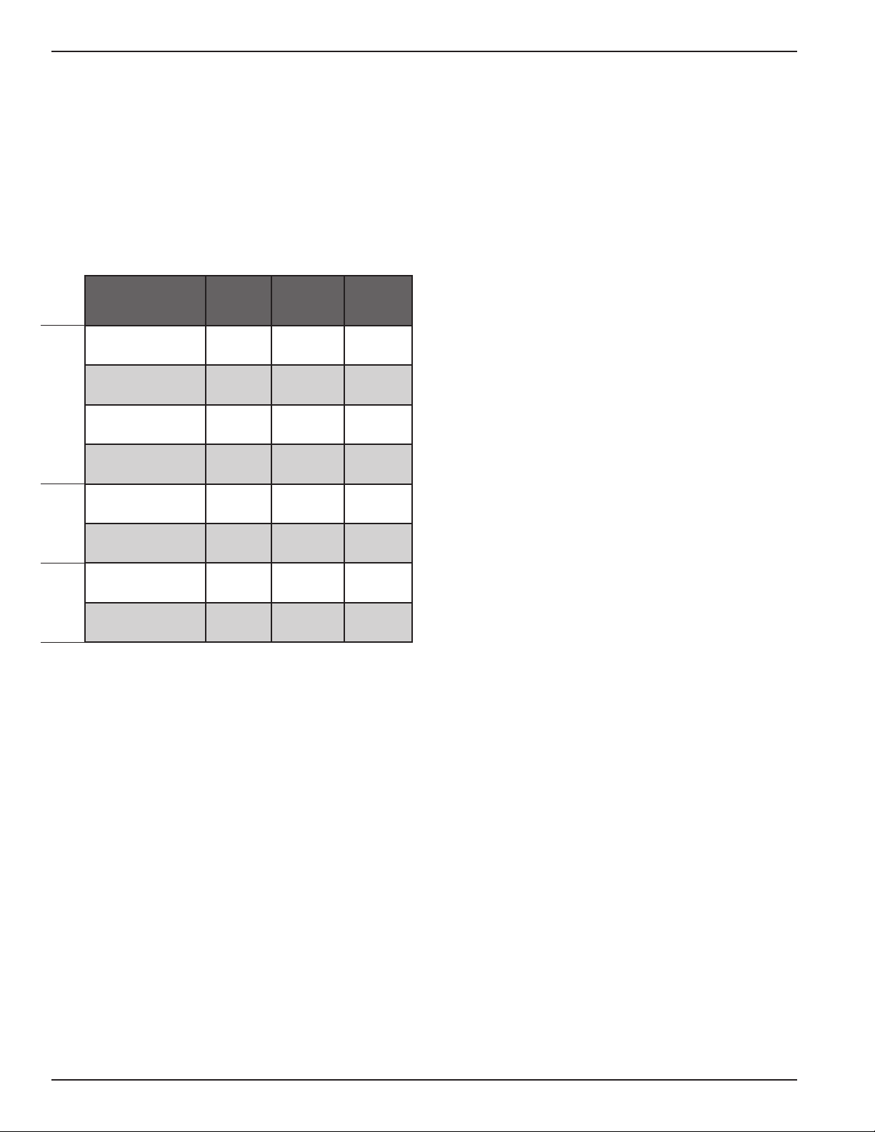
Aircel HP Series User manual

Throughout this manual,
signal words are present to
advise of safety precautions
and/or standard practices.
Obey these signal words as defined
below:
DANGER! - indicates an
imminently hazardous situation
which, if not avoided, will result
in death or serious injury.
WARNING! - indicates a
potentially hazardous situation
which, if not avoided, could
result in death or serious injury.
CAUTION! - indicates a
potentially hazardous situation
which, if not avoided, may
result in minor or moderate
injury.
Notice: - used to address
practices not related to personal
injury. This manual is property of the owner, and should be left with the unit when
start-up is complete. Aircel LLC. reserves the right to change design and
specifications without prior notice.
Installation,
Operation, and
Service Information
Aircel
HP Series Non-Cycling Refrigerated Air Dryer
Models: HP-45, 65, 80, 125, 200, 260, 415, 570, 860, 1000, 1400
Installation
and Operation Manual

2
WARNING!
General Safety Procedures
• Improperinstallation,operation,ormaintenancemaycontributetoconditionsinthework
areaorfacilitythatcouldresultinpersonalinjuryandproductorpropertydamage.Check
that all equipment is properly selected and sized for the intended use.
• Consultandcomplywithnationalandlocalcodesrelatingtofireorexplosionandall
other appropriate codes when determining the location and operation of this equipment.
• Safeandefficientoperationoftheunitdependsonproperinstallation.
• Authoritieswithjurisdictionshouldbeconsultedbeforeinstallingtoverifylocalcodesand
installationprocedures.Intheabsenceofsuchcodes,installunitaccordingtotheNational
ElectricCode,NFPANo.70-latestedition.
• Aqualifiedinstallationandserviceagentmustcompleteinstallationandserviceofthis
equipment.
• DONOTweldon/topressurevesselormodifyitinanyway.
• DONOTremove,modify,oradjustprotectiveorsafetydevices.
• Lockoutpowersupplyanddepressurizesystembeforeperformingmaintenanceorservice
work.
• DONOToperatetheequipmentwiththecontrolpaneldooropen.
Notice: Foroptimumperformance,useonlyAircelreplacementparts.
Notice: Foroptimumperformance,useonlyoriginalequipmentreplacementparts.
Notice:Forinformationandnotesspecifictoacustomdesignedandbuiltdryer,referencethe
drawingpackageprovidedwiththeunit.Seewarrantyonmanualbackcoverfor
custom engineered products.
Aircel HP Series

Non-CyclingRefrigeratedAirDryer
3
Contents
SafetyStatements .................................................. 2
DataSheet............................................................. 4
RefrigerantSafetyPrecautions .............................. 5
DesignParameters................................................. 6
Description............................................................ 6
System.......................................................... 6
RefrigerationCircuit .................................... 7
Compressed Air Circuit................................ 7
PurposeandIntendedUse..................................... 9
InspectiononArrival ............................................ 9
LiftingInformation ............................................. 10
InstallationCodesandProcedures ...................... 10
Installation.......................................................... 11
TypicalInstallation ............................................. 12
PreliminaryStart-UpChecklist............................ 12
AutomaticDrainValveAdjustments................... 14
OperatingProcedure ........................................... 14
AirCooledCondenserRequirements .................. 14
CoolingWaterRequirements.............................. 15
Water Cooled Condenser Table ................. 15
Thismanualcontainsspecificprecautionarystatementsrelativetoworkersafety.
Readthoroughlyandcomplyasdirected.Discusstheuseandapplicationofthisequipment
witharepresentative.Instructallpersonnelonsafeuseandmaintenance
procedures.Understandandobeythefollowingsignalwordsusedinthismanual.
•DANGER! - indicates an imminently hazardous situation which, if not avoided, will
result in death or serious injury.
•WARNING! - indicates a potentially hazardous situation which, if not avoided, could result
in death or serious injury.
•CAUTION! - indicates a potentially hazardous situation which, if not avoided, may result in
minor or moderate injury.
•Notice: - used to address practices not related to personal injury.
Shut-DownProcedures........................................ 16
Shut-DownEmergency............................... 16
Short-TermShut-Down.............................. 16
ServiceInformation............................................. 17
Maintenance............................................... 17
Troubleshooting.................................................. 19
Electrical ................................................... 19
Refrigeration .............................................. 19
CondensateRemoval.................................. 20
Other.......................................................... 20
Troubleshooting Table........................................ 21
Appendix ............................................................ 26
R-134ARefrigerantMSDS......................... 26
R-404ARefrigerantMSDS......................... 31
WiringDiagram ......................................... 38
ServiceNotes ...................................................... 45
Warranty............................................................. 48

4
Data Sheet
ModelNumber_____________________________________ SerialNumber________________________________________
DateofManufacture ________________________________
ShipDate __________________________________________ InstallationDate______________________________________
CustomerName
Address __________________________________________________________________________________________
__________________________________________________________________________________________
A c c e s s o r i e s ___________________________________________________________________________________________________________________
O t h e r __________________________________________________________________________________________________________________________
Aircel HP Series

Non-CyclingRefrigeratedAirDryer
5
Refrigerant Safety Precautions
Refrigerant First Aid Recommendations
Inhalation
Ifhighconcentrationsareinhaled,immediately
remove individual from affected area to an area
with a fresh air supply. Keep individual calm.
Ifnotbreathing,giveartificialrespirationorif
havingdifficultybreathing,giveoxygenandcallfor
emergency services.
Skin Contact
Incaseofcontactwiththeskin,immediatelyflush
skinwithcleanwaterforatleast15minutes.Treat
for frostbite if necessary by gently warming affected
areasandcallforemergencyservices.Removeany
contaminated clothing or shoes.
Eye Contact
Incaseofcontactwiththeeyes,immediatelyflush
eye(s)withcleanwaterforatleast15minutesand
call for emergency services.
CAUTION!
Inhalation, Skin, & Eye Irritant
• Usepropersafetyandprotective
equipment, including chemical
safety goggles or face shield and
impervious gloves when handling
refrigerants.
• Exercisecaretoensurethatliquid
refrigerant does not come in contact
withyourskinoreyes.
• DONOTSMOKE.
• Ventilationinworkareamustbe
adequatetokeeptheconcentration
ofrefrigerantbelow1,000ppm.
• Systemmustbefreeofallrefrigerant
before any welding or brazing can be
performed and must be done in a
well ventilated area.
• Decompositionofrefrigerantsis
hazardous! This material can be
decomposed by high temperatures
caused by an open flame.
Hydrofluoric acid and possibly
carbonyl fluoride can form in a
liquid or gaseous state. Avoid
exposuretothesetoxicfumesand
irritating materials.
• Leavetheworkareaimmediatelyif
youexperienceanyofthefollowing:
smell something unusual, feel light-
headed,experienceshortnessof
breath, feel a tingling sensation in
your fingers or toes, suddenly feel
warm or a rapid heartbeat.

Design Parameters
Type of dryer: Refrigerated
Power supply: 115, 230, 460 Volt / single or three
phase / 60Hz
Refrigerant.type: R-134A
R-404A
ChemicalComposition:HFC
Parameter
Description
Optimum Maximum Minimum
AirPressure(psig) 100-125 *See Data
Label 225
AirInlet
Temperature(°F) 80-100 140 40
Ambient
Temperature(°F) 75 120 35
Evaporation
Temperature(°F) 35-42 60 33
SuctionGauge
Reading(psig) 28-40 60 28
DischargeGauge
Reading(psig) 160-230 260 80
SuctionGauge
Reading(psig) 75-90 130 75
DischargeGauge
Reading(psig) 290-400 450 160
Description
System
The non-cycling refrigerated air dryer product covers
the flow range listed on the manual front cover and
provides reliable dew point performance in most flow
conditions. Through optimization
of critical dryer components – heat exchanger,
separator, and condensate removal – the system
ensures the highest performance at full- and partial-
load conditions. R-134a refrigerant is used in dryer
models AR-45 through AR-1000 while R-404A is used in
the AR-1400 and higher models. R-134a is a pure
refrigerant providing consistent performance (zero
temperature glide) and easy service (no mixture of
different refrigerants). R-404A is a blend of three pure
refrigerants: 52% R-143A, 44% R-125, and 4% R134A
(by mass). This blend is nearly azeotropic meaning it
has a negligible temperature glide. R404A is well suited
to larger equipment as the higher operating pressures
and improved heat transfer properties allow for smaller
condensers, which leads to air dryers with smaller
footprints.
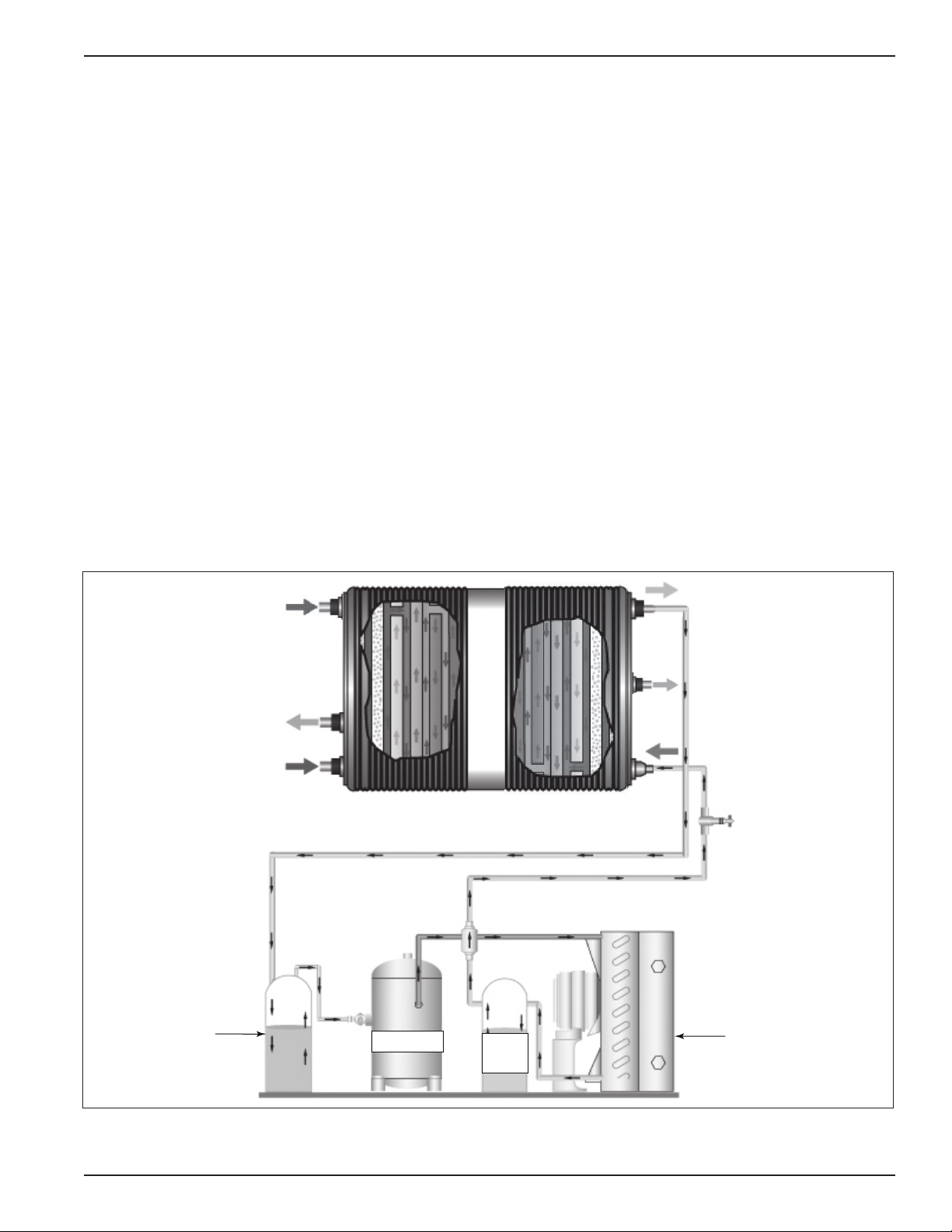
Hot saturated air enters the air-to-air heat
exchanger of the Non-Cycling Refrigerated Air Dryer
and is precooled by the outgoing dry air.
Precooling saves energy by reducing the heat load
on the dryer’s compressor. The cool saturated air
enters the air-to-refrigerant heat exchanger where
air temperature is lowered to the 38 to 42°F range.
This dramatic temperature drop condenses water
and oil.
The mixture of cold air and condensation then
flows into the two-stage separator filter where
liquids and contaminants are removed by
centrifugal action, directional flow change, and
velocity reduction. Once bulk liquids have been
removed, the compressed air goes through a
stainless steel mist eliminating filter that coalesces
oil aerosols and oil vapors within the 100-micron
range, and then separates and removes them. At
this point, the compressed air is dry and virtually
oil-free.
Cold, dry air exits through the precooler heat
exchanger and is reheated by incoming hot air.
Reheating restores energy and also prevents
condensation from forming on the outside of air
distribution piping. In the refrigeration unit, the
compressor pumps hot, high-pressure gaseous
refrigerant to the condenser where it is cooled
and liquefied by ambient air. From the condenser,
liquid refrigerant first flowsthrough the receiver,
then through a filter/dryer, and finally through the
expansion valve where pressure and temperature
are reduced. This reduction in pressure causesthe
liquid refrigerant to boil until it reaches the s
aturation temperature that corresponds to its
pressure. As the low-pressure refrigerant passes
through the evaporator, heat flows from the
compressed air to the refrigerant, causing the
boiling to continue until all refrigerant is vaporized.
Refrigerant gas is returned to the compressor and
the cycle is repeated. A hot gas by-pass valve is used
to control temperature in the evaporator.
6
Aircel HP Series
All Models
R-134AR-404A

Refrigeration Circuit
Refrigerant is compressed by the compressor to a
gas with high temperature and high pressure, which
then travels to the condenser (air or water cooled)
to condense the gas into a liquid. Liquid travels to
the evaporator (refrigerant-to-air part of the heat
exchanger) and back to the compressor suction
side. The process then repeats. A thermal expansion
hot gas by-pass valve is used on the non-cycling
dryers as a freeze protector in low load conditions
([1-1/4 HP] and up).
Compressed Air Circuit
exchanger. This energy saving heat exchanger
provides several advantages, such as a reduction
of the heat load imposed on the refrigerant
compressor and condenser, providing more
energy to the outlet air, and preventing
condensation of moisture on the outside of the
plant distribution air line piping. From the
air-to-air heat exchanger, air will enter into the
evaporator further reducing its temperature
to a desired pressure dew point. As the air is
cooled, moisture is condensed, separated, and
discharged through the condensate drain. The
cooled air then reenters the air-to-air heat
exchanger, in a direction opposite to the flow
of the warm, saturated incoming air. This
counter flow action assures high temperature
differential throughout the heat exchanger,
resulting in a more effective heat transfer.
7
Non-CyclingRefrigeratedAirDryer
compressor liquid
receiver
refrigerant
outlet
air out refrigerant
inlet
air in
suction air cooled
accumulator condensor
Air to Refrigerant Heat Exchanger
Refrigerant Circuit
Typical Schematic Flow Diagram
The compressed air dryer circuit uses a patented
air-to-air heat exchanger, which acts as a precooler/
reheater. Hot, saturated, compressed air first enters
the air-to-air heat exchanger, where it is pre-cooled
by outgoing air from the air-to-refrigerant heat
air to water
separator
air from water
separator

Non-CyclingRefrigeratedAirDryer
9
Purpose and Intended Use
Non-cyclingrefrigeratedairdryersaredesigned
to remove moisture from compressed air by use of
mechanical refrigeration. They can provide pressure
dewpointsaslowas(38°F-42°F).Referigerated
dryers are used to protect industrial compressed air
systems,machinery,andtools.Toensuremaximum
performance and safe operation of this dryer,
everyone associated with its installation, operation,
and maintenance must read, understand, and follow
the instructions of this manual.
CAUTION!
• Donotmisuseormodifyunderany
conditions.Misuseormodification
of this equipment may result in
personal injury.
Inspection on Arrival
All non-cycling refrigerated air dryers are tested
and operated before shipment. However, shipping
stresses have the potential to cause damage to
the unit. To ensure smooth installation, it is
recommended that immediately upon receipt of the
unit,thesystemischeckedforthefollowing:
1. Reportanydamagetothedeliverycarrier.
2. Requestawritteninspectionreportfromthe
ClaimsInspectortosubstantiatetheclaim.
3. Fileclaimswiththedeliverycarrier.
4. Compare unit received with description of
productordered.Checktheserialplatelabel
andmakesurethatitisthecorrectModelwas
ordered.NotetheequipmentCapacityand
PowerSupplyrequirementsandensurethatthey
are in accordance with your specifications. The
rated conditions of the dryer are indicated on
theserialplatelabel.Ifthereisanydiscrepancy,
contact your representative listed on the manual
backcover.
5. Shippingstressescanloosenconnections.
All pipe and tubing connections should be
inspected.
6. Observe pressure of refrigerant suctions gauge
todetermineifrefrigeranthasleakedduring
transit.Ifthegaugereadingdoesnotmatchthat
mentioned on the serial plate label, immediately
contactTechnicalSupportlistedonthemanual
backcover.
7. Reportincompleteshipmentstothedelivery
carrier and your service representative.

Lifting Information
1. Useallliftingpointsprovided.Specialcaremust
be used when lifting the dryer to prevent tip-
over.
2. Useclevisconnectors,nothooks,onlifting
slings.
3. Only lift unit under support frame/base by using
theforkliftopeningsprovided.Donotliftby
piping.
4. Checktheapproximateweightprovidedon
the specification control drawing to ensure
adequatelifttruckcapacity.
5. Allow only qualified operators to lift the
equipment.
6. RefertoapplicableOSHAregulationsandlocal
codeswhenusingcranes,forklifts,andother
lifting equipment.
WARNING!
• Failuretolifttheunitcorrectlycan
result in severe personal injury or
property damage.
• Useappropriateliftingequipment
and adopt all safety precautions
needed for moving and handling the
equipment.
• Ahandcart,forkliftorcraneis
recommended for unloading and
installation.
• Liftunitbyliftinglugsandframe
only.Donotliftbypiping.
Installation Codes and Procedures
WARNING!
• Followproperlockout/tagout
procedures before performing
serviceormaintenancework.
• Electricalinstallationmustbe
performed by a qualified electrician
and comply with all applicable
national and local codes.
1. Safeandefficientoperationoftheunitdepends
on proper installation.
2. Authorities with jurisdiction should be
consulted before installing to verify local codes
andinstallationprocedures.Intheabsence
of such codes, install unit according to the
NationalElectricCodeandNFPANo.70-latest
edition.
3. A qualified installation and service agent
versed in all regulatory codes must complete
installation of this unit.
CAUTION!
• AcopyoftheOperationManual
must be made available to all
personnel involved with the
installation, operation and
maintenance of the equipment,
to avoid injury to personnel or
property damage.
• Appropriatetoolsmustbeusedfor
all installation and maintenance
work,toavoidinjurytopersonnel
or property damage.
10
Aircel HP Series

Installation
1. Locateunitonalevelfoundation.Dryershould
be mounted on a suitably structured flat and
level floor or base that is free from vibration.
2. Installunittoprovideadequateclearancefor
maintenanceservices.Dryerandaccompanying
filters should be installed with at least 2 to
5 feet clearance from the adjoining walls to
provide easy access for routine maintenance and
adequate air flow across the condensing coil.
3. The frame or cabinet must be securely bolted
to the foundation to prevent movement
resulting from earth tremors and induced piping
vibration.
4. Installunitusingthecorrectpipesizeand
pressurerating.Seedrawingpackageprovided
with the unit. Connect the inlet of the dryer to
themoistgasfromtheinletfilter.Installthe
inletpipingandtheinletshutoffvalve.Install
the outlet piping and the outlet shutoff valve
(a union with a valve by-pass can be installed
at the inlet and outlet valves to accommodate
isolation of the dryer for maintenance).
Compressed air piping has to be at least
the same size as that of the inlet and outlet
connections of the dryer. Larger pipe sizes can
be used with appropriately rated reducers.
Operation at elevated pressure or temperature
may cause damage to the dryer or serious injury
topersonnel.Eachdryerischeckedatthe
factory for proper operation at the conditions
noted on the serial plate label.
5. Provideadequatepowersupply.SeeDesign
Parameterssection.Makeallelectrical
connections to the dryer as shown on the
wiringdiagram.Specialcaremustbetakenin
connecting the proper voltage as indicated on
the specification sheet and wiring schematic.
Itismandatorythatthedryerbegrounded.
Useofyourplant’sframeasagroundmay
cause problems with the controls. A fused
disconnect is not supplied with this equipment;
therefore, one must be supplied by customer.
Allelectricalfuses,breakers,etc.shouldbe
sized by a qualified electrician and comply with
all applicable national and local codes. Our
company is not liable for any code violations,
component damage, downtime or consequential
damage related to customer supplied electrical
components and connections.
6. The ambient temperature should be between
45°Fand100°F.Lowtemperaturecouldaffect
the dryer process and result in high outlet dew
point.Inconditionswheretheambientdrops
below freezing, it is recommended that a heat
trace be used for the equipment. This will
ensure trouble-free operation during the winter
months (the dew point of the outlet air will be
consistent).*Insomecases,aheadpressure
control valve may be needed. (optional)
7. Donotplacethesysteminserviceuntilthe
above steps have been completed and that all
ratings and specifications have been verified to
matchtherequirementsinthedrawingpackage
supplied with the unit.
8. Ifthereareanychangesintheoperating
conditions of the system from those published
inthismanual,contactTechnicalSupport.
11
Non-CyclingRefrigeratedAirDryer

Preliminary Start-Up Checklist
Notice:Forscfmratedmodels45-260,wait
at least 6 hours after transporting or
moving of dryer system before starting
the dryers. Turn the main power switch
to the dryer on, but do not turn the
dryer on/off switch to the on position
until 6 hours have passed.
Forscfmratedmodels415andlarger,
ensure that the power switch is in
the“off” position, but the electrical
service to the dryer is energized. This
dryer must be in this mode for at
leasttwelve(12)hourstoallowthe
compressorcrankcaseheatertoenergize
and evaporate any liquid refrigerant
fromthecompressor.Aftertwelve(12)
hours,turnONthepowerswitchof
the dryer. The power indicating light
shouldturnON.
TypicalInstallation
Typical Installation
12
1. Checkthattheinletandoutletconnections
are the correct size and pressure rating, and
tightened securely.
2. Checkthatthecorrectpowersupplyis
connected to the non-cycling refrigerated air
dryer system with an adequate disconnect
switch.
3. Checkthatallcompressedairlineservicevalves
are open and that compressed air is available to
be supplied to the non-cycling refrigerated air
dryer system.
4. Checkthatallliquiddrainservicevalvesare
open.Thisistoensurethatanyresidualbulk
condensate that may have accumulated in the
compressed air lines is discharged immediately
upon start up. These drains must be closed
once system is brought on line for use. The
drain valve on the refrigerated air dryer can be
opened by pushing the test button located on
the drain body.
Aircel HP Series

5. With the customer-supplied compressed air
tothesystem,OPENtheinletvalveslowlyto
graduallypressurizethesystem.Donotopen
valvetooquickly.Openingvalveandsuddenly
pressurizing the system can cause damage to the
dryerheatexchangerandothercomponents.
6. Checktheairsystempipingconnectionsand
dryersystemconnectionsforleaksatthistime.
Repairandretestanyleaks.
7. Verifythatallinstrumentation(pressure
gauge/s) and drain air tubing fittings are tight.
8. Ensure that the air system has come up to
full pressure and has filled the dryer with
compressed air. Before opening the outlet valve
on the system and after the dryer has been
started under no load, let the dryer run for at
leastfifteen(15)minutestoallowstabilization
of the system. Verify the following:
a. The dryer is designed to run continually
and should not be cycling on and off with
the air compressor. The non-cycling
operation of the dryer is controlled by an
automaticexpansionvalveorathermostatic
expansionvalve/hotgasby-passvalve.The
valves will open and close automatically
depending on the of heat load to the
evaporator, thus maintaining the desired
pressure dew point.
b. Checktheinletcompressedairtemperature
and pressure to the dryer and verify that it
meets the specified requirements.
c. Fanrotation,fordryerswithanair-cooled
condenser, rotation should be in accordance
with the fan rotation shown on the details
locatedontopandbackofthecondenser.
Cooling air is drawn through the condenser
coils.Ifthemotorrotationisnotcorrect,
turn off the power switch and put the main
power supply disconnect in the “off”
position;lockandtag;checkthewiring;
correctthewireleadlocations;recheckfor
correct rotation.
13
Non-CyclingRefrigeratedAirDryer
d. The refrigeration gauge readings should be as
follows:
• Refrigerant suction pressure:
R-134A =28-40 psig
R-404A = 75-90 psig
•Refrigerant.dischargepressure:
R-134A = 160-230 psig
R-404A = 290-400 psig
Notice:Theabovedischargepressuresdepend
upon ambient temperature and can
vary slightly according to temperature
fluctuations.
9. Afterthepreliminarystartupchecklisthasbeen
completed, the compressed air outlet valve on
the dryer system can now be slowly opened to
supply clean dry compressed air to the facility.
10. Afterstart-upandapproximatelyonemonth
ofservice,checkthatallpipingandfittingsare
tightandfreeofleaks.
Notices:
• Modelswiththehotgasby-passvalvesand
expansionvalvesarepresetatthefactory
for the desired dew point. Donotadjust
without consulting with the factory.*
• Thedryersarefullyautomaticanddonot
requireanyauxiliarycontrols.
*Adjustments not authorized by the
factory may void the warranty.

Automatic Drain Valve Adjustments
The automatic drain valve supplied is standard on the
separator and should open regularly and discharge
any accumulated water into the drain line. The
period between openings varies with the dryer and
operating conditions (electronic type). To minimize
air losses, the timer should be adjusted to open
the drain solenoid just long enough to discharge
the accumulated condensate. The factory sets the
automaticdrainstoopenfor7secondsaboutevery7
minutes.Ifmorethantwosecondsofdryaircomes
out at the end of every discharge cycle, reduce the
open time (seconds) or increase the interval of the
discharge(minutes)tominimizeairloss.Ifliquid
is still being discharged when the discharge cycle
stops, increase the open time (seconds) or shorten the
interval of discharges (minutes) so it discharges more
often.
Operating Procedure
After the initial startup, the dryer operation is
completely automatic. To understand the details of
theoperation,seetheflowdiagramonpages7and8.
Model by
SCFM Rating
Refrigeration
Hp
Cooling air
flow (cfm)
45 1/5 275
65 1/4 300
80 1/3 300
125 1/2 350
200 3/4
260 1 1/4 750
415 1 1/2 1250
570 3000
860 3 1/2 3000
1000 55000
1400 55000
14
Air Cooled Condenser Requirements
Cooling air must be drawn from a clean source to
reduce dust and dirt accumulation on the condenser
coils.Airtemperatureshouldnotexceed100°F
(38°C).
Aircel HP Series
2
525

Cooling Water Requirements (water cooled
condensing units)
Cooling water is required for water-cooled
refrigerant condensers. The user is responsible for
piping the water to and from the condenser. The
required water flow rate depends on the water
temperature. A water-regulating valve (supplied
with the dryer) automatically adjusts the flow to
compensate for variation in water temperature,
(CF)-ConsultFactory
Notices:
• Watercooledcondensersarepre-setatthefactoryforcitywaterusage.
• Waterregulatingvalvemayneedtobeadjustedtootherwatersupplyconditions.Contacttechnical
support for assistance.
• Minimumwaterpressureis25psigforcitywaterand35psigfortowerwater.Coolingwater
pressures less than these minimums may reduce dryer drying capacity.
• Maximumwaterpressureis125–150psig.
water pressure, and dryer air load. The table below
indicates the amount of cooling water required
in gallons per minute (gpm) at given incoming
temperatures for the condenser Hp size in each
model. The refrigerant discharge pressure control
will shut down the refrigerant compressor if cooling
is inadequate.
Incoming Water Flow Rate Requirements
(in gpm at different inlet water temperatures)
Model by
SCFM Rating Condenser Hp 70°F 80°F 85°F 90°F
1 1.25 1.5 CF
1.5 1.9 2.25 CF
2 2.5 3 CF
33.75 4.5 CF
456CF
7 8.75 10.5 CF
10 12.5 15 CF
12 15 18 CF
14 17 20 CF
15 19 24 CF
Water Cooled Condenser Requirements Table
15
Non-CyclingRefrigeratedAirDryer
1/4
1/3
1/2
3/4
1 1/2
2
5
5
65
80
125
200
260
415
570
860
1000
1400
3 1/2
1 1/4

Shut-Down Procedures
Shut-Down Emergency
The non-cycling refrigerated air dryer system can
be shut down under any conditions and at any time
by turning the unit off at the dryer or at the main
disconnect switch. Once power is removed from
the dryer system, the dryer must be isolated from
the compressed air stream to avoid a refrigeration
circuit over pressure situation.
Short-Term Shut-Down (over night or weekends)
The refrigerated air dryer system can be shut down
at any time by turning the unit off at the dryer by
using the on/off switch or at the main disconnect
switch.
WARNING!
• Toavoidpossiblehazardorinjury,
the operator should be fully familiar
with the refrigerated air dryer
system and its operation.
• Whenthesystemisshutdownand
powerremoved,lockoutpower
supply and depressurize system
before performing maintenance
orserviceworktoavoidinjuryto
personnel or property damage.
16
Aircel HP Series

Service Information
To reach a field service technician or for technical
support,pleasecallthenumberonthemanualback
cover.
Maintenance
Refrigeratedairdryersrequireverylittle
maintenance for satisfactory operation. Optimum
performancecanbeexpectedifthefollowing
routinemaintenancestepsaretaken.
WARNING!
• Beforeanyserviceormaintenance
workisperformedonthe
refrigerated air dryer system,
disconnectpowersupplyandlock
out power supply and depressurize
system before performing
maintenanceorservicework.
• Followproperlockout/tagout
procedures before performing
serviceormaintenancework.
• Priortoperformingany
maintenance on the dryer, all
personnel are strongly advised to
familiarize themselves with the
equipment by reading the entire
contents of this operation manual.
Followallsafetyprocedurespriorto
performing any maintenance activity
on the dryer.
Daily
With the dryer on-line:
• Verifytheoperatingpressure,temperature,and
flow rate are correct and conform to those listed
intheDesignParameterssection.Adjustsystem
if required.
• Alwayscheckrefrigerantgaugestoinsure
refrigerationsystemisworkingproperly.
• Checkcondensatedrainseparatorforproper
condensatedischarge.Ifnodischargeisevident
then depressurize the unit, dismantle and clean
separatorand/ordrainline.Properdraintrap
maintenanceistheowner’sresponsibility.Itis
not covered by warranty.
• Makecertainairflowisdirectedthroughdryer
only. Observe by-pass valves proper positions.
Weekly
• Repeatalldailyinspectionsandrecorddatain
the maintenance log.
• Cleanthecondensercoilsofaccumulated
dust and dirt with a soft brush and/or with
air pressure from a compressed air nozzle
(maximum100psig).
• Checkthegaugereadingsforoptimumsystem
operation.
• Checkoilremovalfilter(coalescer)indicator(if
applicable); if it is red, replace the filter.
17
Non-CyclingRefrigeratedAirDryer

Filter Element Replacement
1. Depressurizetheairsystemtorelease
the compressed air from the air dryer.
Notice:Shuttingdowntheaircompressorwill
not depressurize the air dryer unit.
Close air line valves before and after
dryer and then depressurize unit.
Depressurizedryerbypushingthetest
button on the dryer system drain until
there is no more pressure in the dryer
system.
2. Removethefilterbowlbyturningthebowl
1/4turncounterclockwise,besuretheO-ring
is in place on the top half of the oil filter
housing and that the O-ring seats properly. Air
leaksmayoccuriftheO-ringisnotsecured
(important).
3. The same procedure applies when removing
the filter separator for changing the element (if
applicable).
18
Aircel HP Series

Troubleshooting
WARNING!
• Beforeanyserviceormaintenance
workisperformedonthe
refrigerated air dryer system,
disconnectpowersupplyandlock
out power supply and depressurize
system.
• Followproperlockout/tagout
procedures before performing
serviceormaintenancework.
• Priortoperformingany
maintenance on the dryer, all
personnel are strongly advised to
familiarize themselves with the
equipment by reading the entire
contents of this operation manual.
• Followallsafetyprocedurespriorto
performing any maintenance activity
on the dryer.
Ifthereisaproblemwiththerefrigeratedairdryer
or contamination down stream is present, the
problem may be identified from one or more of the
following sources:
• Electrical
• Refrigeration
• Condensateremoval(drains)
• Other
• Makecertainthatthedryerisconnected
to proper power supply in accordance with
electrical diagram provided.
• Checkelectricalbreaker,fuse,ordisconnectto
determine if there is electrical power to the unit.
• Aquickcheckshoulddetermineifthepower
switch is turned on and the unit is running.
• Afterdeterminingthatpowerissuppliedtothe
unit,gotothenextstep.
Refrigeration
WARNING!
• Followproperlockout/tagout
procedures before performing
serviceormaintenancework.
• Electricalinstallationormaintence
must be performed by a qualified
electrician and comply with all
applicable national and local codes.
19
Non-CyclingRefrigeratedAirDryer
Electrical
WARNING!
Refrigeranthandlingmustbeperformed
by a qualified technician and all
applicable national and local codes
must be followed.
Notice: Alwaysobserverefrigerantpressure
gauge(s) to determine if and how
refrigeration circuit is operating.
Non-cyclingrefrigeratedairdryerswithR-134a
refrigerant should have a suction gauge pressure
readingof28-40psigandadischargegauge
pressurereadingof160-230psigwiththeunitinthe
onpositionunderfullorpartialload.Ifthe
refrigerant gauge(s) reads more or less than the
above specified pressures, troubleshoot items on the
following page.

WARNING!
Before any service or maintenance
workisperformedontherefrigerated
air dryer system, disconnect power
supplyandlockoutpowersupplyand
depressurize system before performing
maintenanceorservicework.
20
1. Highrefrigerantreadingsgenerallyindicate:
• Dirtycondenser-Cleanimmediately!
• Dryernotturnedon.
• Overloading-Airfloworconditionsin
excessofdryercapacity.
• Highambienttemperature(>100°F)
Provideadequateventilationforproper
cooling, or reduce ambient temperature.
• Condenserfan(s)notrunning-Call
TechnicalSupport.
• Refrigerantcontroltoohigh-Contact
technical support for assistance.
2. Low refrigerant readings generally indicate:
• Lowambienttemperature-Temperatures
below40°F.Increaseambienttemperatures
or install head pressure control valve.
Contact technical support for more
information.
• Refrigerantcontrolsettingtoolow-
Contact technical support for assistance.
• Lossofrefrigerant-CallTechnicalSupport
or qualified refrigeration service.
Condensate Removal
The non-cycling refrigerated air dryer uses a
refrigeration circuit to cool the compressed air
which causes moisture to condense. The condensed
moisture is separated from the dry air and purged
through an automatic drain.
1. Condensatedownstreamofdryer:
• Iftheunitisequippedwithautomaticdrain
override switch, push manual override
button to test drain flow.
• Ensureautomaticelectronictimer(if
applicable) is functioning properly.
• Ensuremoistureseparator(and
coalescer)drainlinesarefreefromblockage.
• Iftheunitisequippedwithy-strainer,
disassemble and clean.
• Ifoilisdownstreamfromthedryer:
- Oil coalescer element is saturated.
-Dryernotturnedonduringairusage.
Other
Sometimesawateroroilproblemdownstream
from the dryer can be identified by an inadvertent
action or inaction by the operator.
• Dryernotturnedonbeforeairusage.
• By-passvalvesinwrongposition.
• Airusageexceedingdryercapacity.
• Oilcoalescerelementdirty.
• Automaticdrainsnotmaintained.
Aircel HP Series

Troubleshooting Table
Non-CyclingRefrigeratedAirDryer
Problem Probable Cause Remedy
Water downstream
of dryer system or no
discharge from separator/
filter.
Failedorshortcircuited
timer on drain.
Replacetimerdrain.
Faileddrainsolenoid. Replacetimerdrain.
Bulkliquidenteringthe
dryer from upstream.
Checkdrainsonaftercooleroraircompressor.
Inletcompressedair
temperature to dryer
exceedsdryercapacityair.
Checkinletairtemperatureandadjustas
required to meet specifications.
InletcompressedairCFM
flowrateexceedsdryer
capacity.
Checkininletaircfmflowrateandadjustas
required to meet specifications.
Leakintheairtoair
sideoftheheatexchanger.
Replaceheatexchanger.
Water downstream and
dryersystemnotworking
properly.
Refrigerationcompressor
stopped due to plugged or
dirty condenser coil.
(HighPressure)
Clean condensing coil and ensure adequate
ventilation of unit.
Refrigerationcompressor
cycles on/off and cannot
maintain suction pressure.
Checkcondensingcoilfordirtordebristhat
could prohibit adequate ventilation of the
refrigerantcircuit.Ifitisclean,checkrefrigerant
pressure gauge(s) to determine if the unit is low
on refrigerant.
Low refrigerant. Checkforleakinrefrigerationcircuit,repairand
recharge according to specifications.
Low refrigerant, possible
leakinairtorefrigerant
sideofheatexchanger.
Repairorreplaceheatexchangerandrecharge
according to specifications.
Refrigerationcompressor
is overheated.
Turnoffdryerandwait20-40minutes,restart
dryer.Refrigerantcontrolsettingsmayneed
adjustment, contact technical support.
Refrigerationcompressor
has burned out or
windings have gone
to ground.
Replacecompressor,checkforleakin
refrigeration circuit, repair and recharge
according to specifications, contact technical
support.
21
This manual suits for next models
11
Table of contents
Other Aircel Dehumidifier manuals