AirCom 50TH.2 HVLP Series User manual


AIRCOM® - INSTRUCTION MANUAL - 2022 - v. 1.0
AVAILABLE MODELS
mod. 50TH.2
Suitable for multiple sectors.
mod. 50TH.2-Q-X
Internal passages in stainless steel.
Presence of optional washing circuit.
It is possible to use the quick release
block, the AIRCOM® QRB.
mod. 50TH.2-QS-X
Internal passages in stainless steel.
Presence of optional washing circuit.
Possibility of equipping the gun with a
bracket block if the AIRCOM® QRB
accessory is not used.

EN
Index
MANUALS
WARNINGS!
Warnings
Maintenance and cleaning
Installation and start-up
Technical data
Troubleshooting
Spare parts and components
Certified quality
Support
Notes
.04
.04
.05
.08
.10
.11
.16
.16
.17
Our manuals are available at aircom.it/en/support/manuals/ Or,
by scanning the QR Code on this page.
Carefully read and follow all instructions and safety precautions
before using the product.
Instruction Manual
50TH.2 series

4 - Instruction Manual aircom.it
EN
WARNINGS
MAINTENANCE AND
CLEANING
MAINTENANCE
CORROSIVE PRODUCT
WARNINGS
CLEANING
HEALTH HAZARD
Before any maintenance work, empty the
gun and disconnect it from both, the
compressed air supply, and the liquid
supply. Use only original AIRCOM®
accessories, spare parts, and related
components: any other product not
supplied by AIRCOM® is not approved or
authorized. AIRCOM® is not liable for any
damage caused by using non-original
spare parts and accessories.
Our guns can be used with the majority
of water, or solvent-based pigments for
coating and finishing all types of
surfaces. However, they are not
designed to spray abrasive and/or
corrosive products. If abrasive and/or
corrosive products are used, guns with
components made of the appropriate
material can be ordered.
Use exclusively appropriate liquid
cleaners with neutral pH 6-8. Do not use
acids, alkaline solutions or other cleaning
agents containing sodium hydroxide,
which are aggressive for cleaning the
exterior of the gun. Do not immerse the
gun in liquid cleaners that may cause
corrosion of the product. Clean all
material passages by propagating water
within the paint circuit: inadequate
cleaning can cause damages to the fan
shape. While cleaning, avoid scratching
the surfaces of the air nozzle holes and
the dipstick.
Some chemicals, once sprayed, may be
harmful and cause irritation or health
disorders. Careful reading of all labels
and instructions on how to use the
product are necessary. Use of the
product is restricted to trained technical
personnel, with the use of special safety
glasses when adjusting the gun and,
while the system is operating.
50TH.2 series

aircom.it Instruction Manual - 5
50TH.2 series
EN
INSTALLATION
TECHNICAL SPECIFICATIONS
VIDEO TUTORIALS
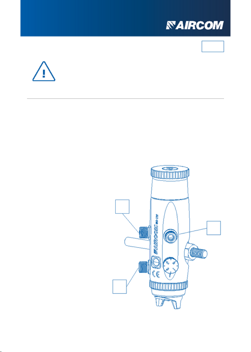
Connection hole diameter: 10,2 mm.
Size of pipe junctions:
• Control air inlet: A = ¼ gas
• Atomizing air inlet: B = ¼ gas
• Product inlet: C = ¼ gas
Gun weight: 0,75 kg
Gun size: see dimensioned views
Our video tutorials are available at aircom.it/en/support/tutorials/
Or, by scanning the QR Code on this page.
66
165
57
10,2
53
►
C
BA
87
47
54
162
6 - Instruction Manual aircom.it
EN
DIRECTIONS FOR GUN
OPERATION
INSTALLATION AND STARTUP
A
Pipe Ø ext. X Ø int. = 8 X 6
Plunger opening ≥ 4,0 bar
B
Pipe Ø ext. X Ø int. = 8 X 6
Atomization: from 1,5 to 3,5 bar
C
Pipe Ø ext. X Ø int. = 8 X 6
Product inlet
Before using a new gun or a new product, clean the gun thoroughly
with an appropriate solvent. Powering should be done with dry,
filtered air and regulated to constant pressure.
C
B
A
50TH.2 series

aircom.it Instruction Manual - 7
50TH.2 series
EN
ADJUSTMENT SEQUENCE
1.Lock the gun to the system using
the fastening bracket and orient the
head towards the appropriate
coverage direction. When using the
-Q version, lock the system block
first, and then hook the gun.
2.Connect the atomization air, control
air and product piping to the
junctions shown on the previous
page.
3.Screw the handwheel part.
[1268-63] as far as it will go (do not
force when reaching the stop). Act
on the control air. If no drop of
pigment comes out, remove the
control air, and open the handwheel
part. [1268-63] with one click.
Repeat the process until the first
drop appears.
4.Open the handwheel part.
[1268-63] with the necessary clicks
to determine the desired amount of
pigment.
5.Act on the adjustment screw to
obtain the desired atomization
range.
15 shots per revolution
0
1
2
34
5
6
7
8910 11 12 13
14
15

NOTES
8 - Instruction Manual aircom.it
EN
TECHNICAL DATA
HEAD
ø NOZZLE SHOTS FLOW RATE OF
THE FLUID ATOMIZATION
PRESSURE AIR
CONSUMPTION
(g/min) (kg/cm²) (L/min)
1268-53-BI
ø 0,8
1268-53-BI
ø 1,5
1268-53-BI
ø 1,0
1268-53-BI
ø 1,2
6
9
7
10
8
11
9
12
115
236
217
275
225
335
302
415
1,5
1,8
2,1
2,3
2,2
2,5
2,5
2,8
Pump pressure 0,8 ÷ 1,0 Kg/cm².
Liquid used for testing: water. Ford cup viscosity 4 = 11 sec.
157
182
194
206
197
217
220
250
HEAD 1268-53-BI
50TH.2 series

NOTES
aircom.it Instruction Manual - 9
50TH.2 series
TECHNICAL DATA
HEAD
ø NOZZLE SHOTS FLOW RATE OF
THE FLUID ATOMIZATION
PRESSURE AIR
CONSUMPTION
(g/min) (kg/cm²) (L/min)
1268-79-BA
ø 1,5
1268-79-BA
ø 1,2
1268-79-BA
ø 1,0
1268-79-BA
ø 0,8
6
9
7
10
8
11
9
12
98
171
173
268
253
348
354
472
1,5
1,8
2,0
2,2
2,3
2,5
2,6
2,8
Pump pressure 0,8 ÷ 1,0 Kg/cm².
Liquid used for testing: water. Ford cup viscosity 4 = 11 sec.
146
171
200
214
191
204
215
240
HEAD 1268-79-BA
EN

10 - Instruction Manual aircom.it
EN
TROUBLESHOOTING
Anomaly Problem / Solution
No atomization
Leakage from the
nozzle
No pressure is getting to the gun
Check air system
Missing product in tank or clogged pipes Fill
tank or clean up with solvent
Lack of product (flow rate too low)
Add product or reduce atomization air
pressure
Mounted handwheel part. [1268-63] worn out
Replace mounted handwheel part. [1268-63] worn
out
Needle part. [1268-54] / nozzle
part. [1268-52] or [1268-73] worn out
Replace needle part. [1268-54]/
nozzle part. [1268-52] or [1268-73] worn out
Valve part. [1007- 43] worn out Replace
valve part. [1007-43] worn out
The head part. [1268-53] or [1268-79], the
nozzle part. [1268-52] or [1268-73], and the
needle part. [1268-54] are worn out.
Replace the head part. [1268-53] or [1268-79], the
nozzle part. [1268-52] or [1268-73] and the needle
part. [1268-54] worn out.
The product is exceeding the amount needed
Reduce the product passage
50TH.2 series

12 - Spare parts and components
NOTES
aircom.it
50TH.2 series
EN
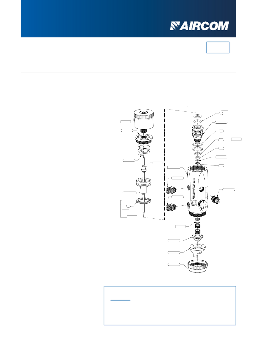
SPARE PARTS
DETAILS LIST mod. 50TH.2
The head protection stopper is also available as a spare
part.
You can refer to the CNN table below for compatible
heads for your model.
[x1]Seeger
[x1]Gasket
[x1]Gasket
[x1]Gasket cover ring
[x1]Valve
[x1]Mounted valve
[x1]Mounted plunger
[x1]Spring
[x1]Plunger
[x1]Nozzle
[x1]Head
[x1]Complete needle
[x1]Ferrule
[x1]Gasket kit
[x1]Cap
[x1]Mounted hand wheel
[x1]Body with brass inner
bushing, adjusting screw
and cap
[x1]Gasket
[x2]Gasket
[x2]Gasket
[x3]Junction
E
1268-63
1268-57
1090-12
1090-100
1090-11
1268-54
1268-55
1268-53
1268-52
1268-G20
1007-R1
1007-R1
1268-56
38
37
39
1007-35
1007-34
L
N
1007-R1
1007-43
37
38
39
1007-34
1007-35
1007-43
1090-11
1090-12
1090-100
1268-52
1268-53
1268-55
1268-56
1268-57
1268-63
1268-67
1268-G20
E
L
N
1007-R1
NOTES
aircom.it Spare parts and components - 13
50TH.2 series
EN
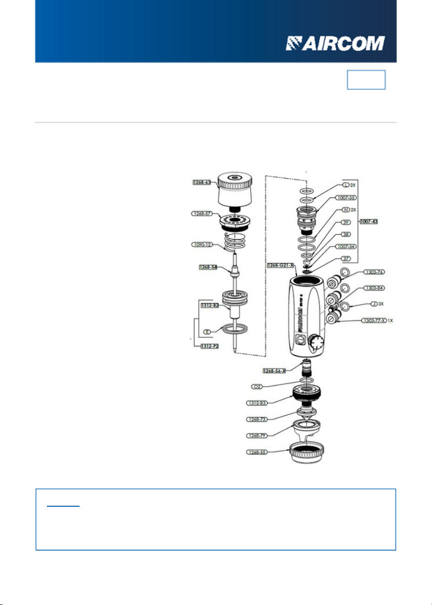
SPARE PARTS
DETAILS LIST mod. 50TH.2-Q-X
The head protection cap is also available as a spare part.
For the heads compatible with the model you can refer to the CNN table below.
The cap foreseen by default in part. [1268-G21-X] can be replaced with a fitting for the
washing circuit.
37
38
39
1007-34
1007-35
1007-43
1090-12
1268-54
1268-55
1268-56-X
1268-57
1268-63
1268-73
1268-79
1268-G21-X
1303-76
1303-77
1303-77-X
1303-84
1312-B2
1312-B3
1312-P2
E
J
L
N
O2
[x1]Seeger
[x1]Gasket
[x1]Gasket
[x1]Gasket cover ring
[x1]Valve
[x1]Mounted valve
[x1]Spring
[x1]Complete needle
[x1]Ferrule
[x1]Stainless steel gasket kit
[x1]Cap
[x1]Mounted hand wheel
[x1]Nozzle
[x1]Head
[x1]Body with stainless steel
inner bushing, adjusting screw
and cap
[x1]Junction
[x1]Junction
[x1]Junction in stainless steel
[x1]Locking pin
[x1]Plunger
[x1]Insert
[x1]Mounted plunger
[x1]Gasket
[x3]Gasket
[x2]Gasket
[x2]Gasket
[x1]Gasket

14 - Spare parts and components
NOTE
aircom.it
50TH.2 series
EN
SPARE PARTS
DETAILS LIST mod. 50TH.2-QS-X
The head protection cap is also available as a
spare part.
For the heads compatible with the model you can
refer to the CNN table below.
The cap foreseen by default in part. [1268-G21-X]
can be replaced with a fitting for the washing
circuit.
37
38
39
1007-34
1007-35
1007-43
1007-R1
1007-R1-X
1090-12
1268-54
1268-55
1268-56-X
1268-57
1268-63
1268-73
1268-79
1268-G21-X
1303-77
1303-77-X
1303-86
1303-R2
1312-B2
1312-B3
1312-P2
E
J
L
M
N
O2
[x1]Seeger
[x1]Gasket
[x1]Gasket
[x1]Gasket cover ring
[x1]Valve
[x1]Mounted valve
[x1]Junction
[x1]Stainless Steel Junction
[x1]Spring
[x1]Complete needle
[x1]Ferrule
[x1]Stainless steel gasket kit
[x1]Cap
[x1]Mounted hand wheel
[x1]Nozzle
[x1]Head
[x1]Body with stainless steel
inner bushing, adjusting screw
and cap
[x1]Junction
[x1]Junction
[x1]Block
[x1]Junction
[x1]Plunger
[x1]Insert
[x1]Mounted plunger
[x1]Gasket
[x3]Gasket
[x2]Gasket
[x1]TCEI Screw
[x2]Gasket
[x1]Gasket
aircom.it Spare parts and components - 15
50TH.2 series
EN
COMPATIBLE CNN
Cap-Nozzle-Needle
mod. 50TH.2-Q-X, 50TH.2-QS-X
mod. 50TH.2
1268-53-BI
1268-79-BA
CAP
1268-53-BI-0.8
1268-53-BI-1.0
1268-53-BI-1.2
1268-53-BI-1.5
1268-53-BI-1.8
CAP
1268-79-BA-0.8
1268-79-BA-1.0
1268-79-BA-1.2
1268-79-BA-1.5
1268-79-BA-1.8
NOZZLE
1268-52-0.8
1268-52-1.0
1268-52-1.2
1268-52-1.5
1268-52-1.8
NOZZLE
1268-73-0.8
1268-73-1.0
1268-73-1.2
1268-73-1.5
1268-73-1.8
NEEDLE
1268-54-0.8
1268-54-1.0
1268-54-1.2
1268-54-1.5
1268-54-1.8
NEEDLE
1268-54-0.8
1268-54-1.0
1268-54-1.2
1268-54-1.5
1268-54-1.8

16 - Instruction Manual aircom.it
EN
SUPPORT
CERTIFIED QUALITY
CERTIFICATIONS
DO YOU NEED HELP?
THREE-COLOR INSERT
We are at your disposal.
All AIRCOM® products are certified
according to norm EN 13 966 - 1 (VDMA-
Einheisblatt 24 366) and therefore also
according to transfer efficiency
parameters.
Each gun is marked with a three-color
three-dimensional seal. It represents an
additional guarantee of authenticity and
Italianity because it is present exclusively
in original AIRCOM® guns.
+39 0124 5154 44 aircom@aircom.it Online support
50TH.2 series

AIRCOM SRL © 2022 - ALL RIGHTS RESERVED

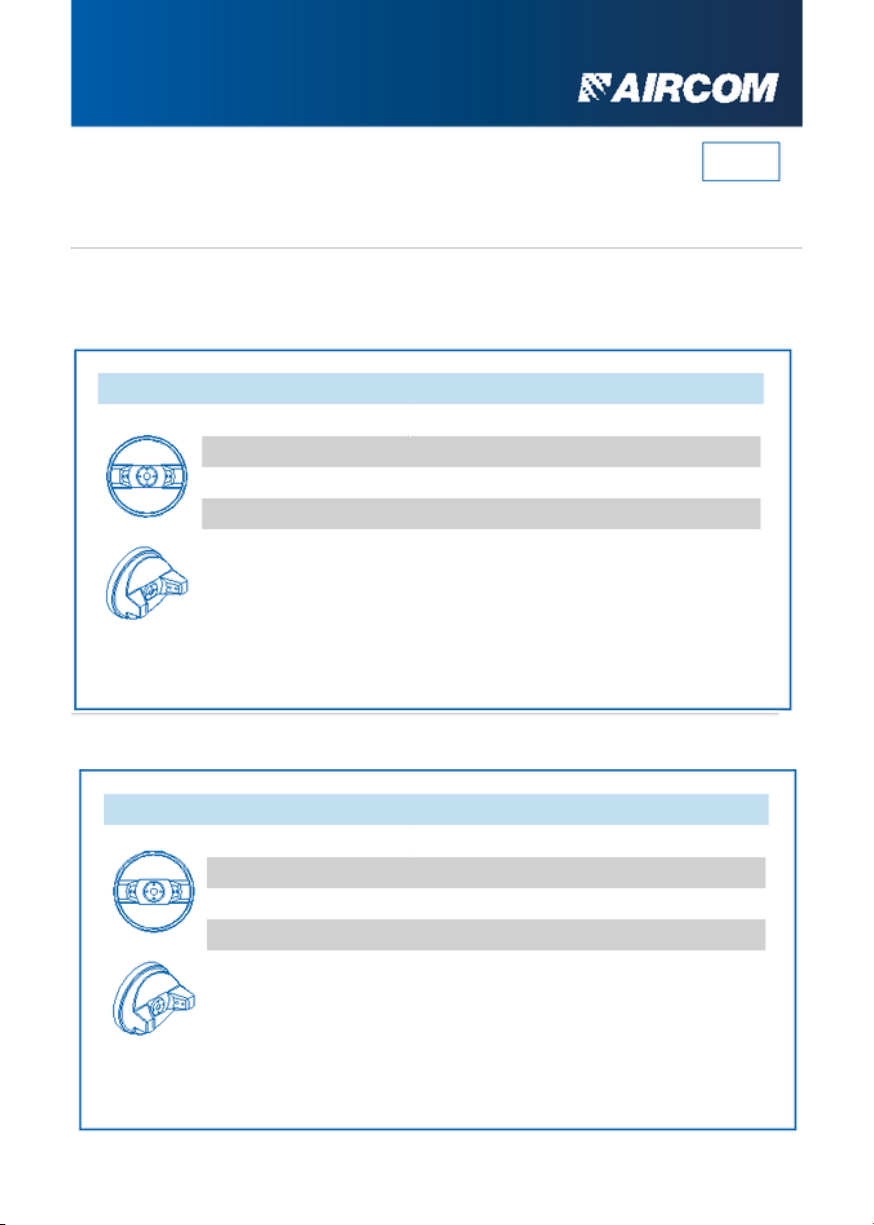
Other manuals for 50TH.2 HVLP Series
1
This manual suits for next models
2
Table of contents
Other AirCom Paint Sprayer manuals

AirCom
AirCom HT Series User manual

AirCom
AirCom A16 Series User manual

AirCom
AirCom LR Series User manual

AirCom
AirCom ECO Series User manual

AirCom
AirCom A81 Series User manual

AirCom
AirCom ECO Series User manual

AirCom
AirCom MG Series User manual

AirCom
AirCom AB HVLP Series User manual

AirCom
AirCom ECO Series User manual

AirCom
AirCom DA Series User manual


