Binks EMG-100-343-K User manual

SERVICE MANUAL
EN
SB-E-2-852-R1.0
Specifications
Maximum Working Pressure
Air (P1) = 9 bar (130 psi)
Fluid (P2 ) = 14 bar (203 psi)
(Pressure only)
Gun Body
Die-cast Aluminium
Fluid Path
Stainless Steel
Fluid Inlet Size
¼” Universal (BSP & NPS)
Air Inlet Size
¼” Universal (BSP & NPS)
Gun Weight
350g
READ ALL INSTRUCTIONS BEFORE OPERATING THIS BINKS PRODUCT
This EMG SeriesTM Spray Gun is a
professional quality spray gun for use
in Gravity, Suction & Pressure feed
spray applications. The lightweight
ergonomic design offers unsurpassed
comfort and control. The latest
atomisation technology has been
incorporated for achieving consistent,
fine finishes when spraying a wide
range of industrial coating
applications.
Binks EMG SeriesTM spray guns are
offered with LVMP atomisation
technology.
IMPORTANT! DO NOT DESTROY
It is the customer’s responsibility to have all operators and service personnel read and understand this manual.
Contact your local Binks representative for additional copies of this manual.
BINKS “EMG SERIES™”
Gravity, Pressure & Suction
LVMP Manual Spray Guns
(EMG-XX-XXX-XX)
II 2 G X

SB-E-2-852-R1.0
EN
Page 2 of 16
READ THE MANUAL
TRAINING
All must be before
equipment.
EQUIPMENT HAZARD
can cause the to
or start and result in injury.
DE- ENERGISE, DE-PRESSURISE, DISCONNECT & LOCK
OUT ALL POWER SOURCES DURING MAINTENANCE.
WEAR SAFETY GLASSES
Failure to wear safety glasses with side shields could result in
serious eye injury or blindness.
PROJECTILE HAZARD
You may be injured by venting liquids or gases that are
released under pressure, or flying debris.
Read the following warnings before using this equipment
NOTE
In this manual, the words WARNING, CAUTION and NOTE are used to
emphasise important safety information as follows:
! WARNING
! CAUTION
INSPECT THE EQUIPMENT DAILY
Inspect the equipment for worn or broken parts on a daily
basis. Do not operate the equipment if you are uncertain
about its condition.
PINCH POINT HAZARD
Moving parts can crush and cut. Pinch points are basically any
areas where there are moving parts.
WEAR RESPIRATOR

EN
SB-E-2-852-R1.0
Page 3 of 16
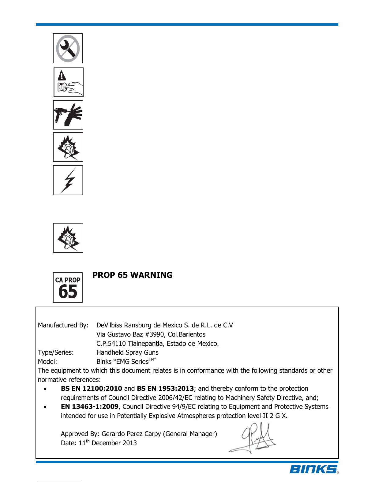
EC DECLARATION OF CONFORMITY
Manufactured By: DeVilbiss Ransburg de Mexico S. de R.L. de C.V
Via Gustavo Baz #3990, Col.Barientos
C.P.54110 Tlalnepantla, Estado de Mexico.
Type/Series: Handheld Spray Guns
Model: Binks “EMG SeriesTM”
The equipment to which this document relates is in conformance with the following standards or other
normative references:
BS EN 12100:2010 and BS EN 1953:2013; and thereby conform to the protection
requirements of Council Directive 2006/42/EC relating to Machinery Safety Directive, and;
EN 13463-1:2009, Council Directive 94/9/EC relating to Equipment and Protective Systems
intended for use in Potentially Explosive Atmospheres protection level II 2 G X.
Approved By: Gerardo Perez Carpy (General Manager)
Date: 11th December 2013
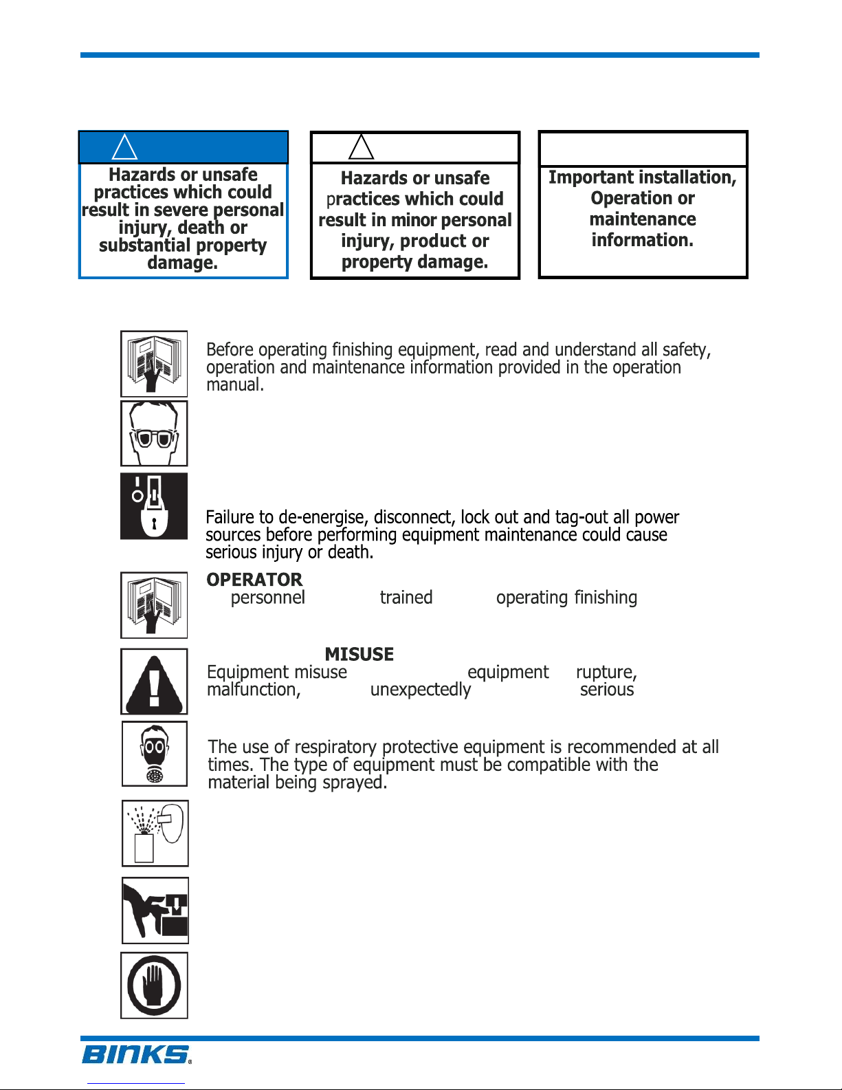
KNOW WHERE AND HOW TO SHUT OFF THE
EQUIPMENT IN CASE OF AN EMERGENCY
PRESSURE RELIEF PROCEDURE
Always follow the pressure relief procedure in the equipment
instruction manual.
NEVER MODIFY THE EQUIPMENT
Do not modify the equipment unless the manufacturer provides
written approval.
STATIC CHARGE
The spray gun must be earthed to dissipate any electrostatic
charges which may be created by fluid or air flows. This can
be achieved through the spray gun mounting, or conductive
air/fluid hoses. Electrical bond from the spray gun to earth
should be checked with an Ohm meter. A resistance of less
than 106Ohms is recommended.
NOISE HAZARD
You may be injured by loud noise. Hearing protection may be
required when using this equipment.
PROP 65 WARNING
WARNING: This product contains chemicals known to the State
of California to cause cancer and birth defects or other
reproductive harm.
FIRE AND EXPLOSION HAZARD
Never use 1,1,1-trichloroethane, methylene chloride, other halogenated
hydrocarbon solvents or fluids containing such solvents in equipment with
aluminium wetted parts. Such use could result in a serious chemical reaction,
with the possibility of explosion. Consult your fluid suppliers to ensure that the
fluids being used are compatible with aluminium parts.

SB-E-2-852-R1.0
EN
Page 4 of 16
NUMBERING SYSTEM
See below for the EMG spray gun ordering code. Charts 1 & 2 show available air cap & fluid tip sizes.
EMG-XX-XXX-XX
Fluid Feed
BG –Gravity
BS –Suction
BP - Pressure
Air Cap
305 = 305MT
307 = 307MT
343 = 343
345 = 345
Fluid Tip Sizes
08 = 0.85mm
10 = 1.0mm
13 = 1.3mm
15 = 1.5mm
18 = 1.8mm
Chart 1 –Air Cap & Fluid Tip Combinations
AIR CAP PART
NUMBER
TIP SIZE (MM)
FEED
AIR
CONSUMPTION
GUN INLET
PRESSURE
PATTERN
WIDTH (mm)
APPLICATION
0.8
1.0
1.3
1.5
1.8
EMG-100-343-K
G
220L/min 0.2MPa
250
Mid-High Volume, fine
atomisation, auto-refinishing,
wood & metal finishing
S
EMG-100-305MT-K
P
200L/min 0.2MPa
250
LVMP, Low-High Volume, fine
atomisation, wood & metal
finishing, auto-refinishing
EMG-100-307MT-K
300
EMG-100-345-K
320
Chart 2 - Fluid Tips & Needles
SIZE
FLUID TIP
NEEDLE
0.8
EMG-200N-08-K
EMG-300N-08-K
1.0
EMG-200N-10-K
EMG-300N-10-K
1.3
EMG-200N-13-K
EMG-300N-13-K
1.5
EMG-200N-15-K
EMG-300N-15-K
1.8
EMG-200N-18-K
EMG-300N-18-K

EN
SB-E-2-852-R1.0
Page 5 of 16
INSTALLATION INSTRUCTIONS
For maximum transfer efficiency, do not use more pressure than is necessary to atomise the material
being applied.
1. Connect the gun to a clean, moisture and oil free air supply, using a conductive hose of at least 8
mm I.D.
NOTE
Depending on hose length, larger I.D. hose may be required.
Install an air gauge at the gun handle. When gun is triggered on,
adjust regulated pressure to 2.0 bar. Do not use more pressure
than is necessary to atomise the material being applied. Excess
pressure will create additional overspray and reduce transfer
efficiency.
NOTE
If quick connect couplings are required, use only high flow quick
connects approved for HVLP use. Other types will not flow enough
air for correct gun operation.
2. SUCTION MODELS ONLY.Attach the cup lid assembly to the fluid inlet connector (6).
3. GRAVITY MODELS ONLY. Attach the gravity cup to the fluid inlet connector (6).
4. PRESSURE FED MODELS ONLY. Connect the fluid supply hose to fluid inlet connector (6).
NOTE
Before using the spray gun, flush it with solvent to ensure that the
fluid passages are clean.
OPERATION (SUCTION/GRAVITY MODELS)
5. Mix coating material to manufacturer’s instructions and strain material.
6. Fill the cup to no more than 20mm from the top. DO NOT OVERFILL.
ALL MODELS
7. Turn fluid adjusting knob (20) clockwise to prevent fluid needle movement.
8. Turn pattern valve adjusting knob (21) counter clockwise to fully open.
9. Adjust inlet air pressure if required.
10. Turn fluid adjusting knob counter clockwise until first thread shows.
11. Test spray. If the finish is too dry, reduce airflow by reducing air inlet pressure.
12. If finish is too wet, reduce fluid flow by turning fluid adjusting knob (20) clockwise. If atomisation is
too coarse, increase inlet air pressure. If too fine, reduce inlet pressure.
13. The pattern size can be reduced by turning pattern valve knob (21) clockwise.
14. Hold gun perpendicular to surface being sprayed. Arcing or tilting may result in uneven coating.
15. The recommended spray distance is 150-200 mm.
16. Spray edges first. Overlap each stroke a minimum of 75%. Move gun at a constant speed.
17. Always turn off air supply and relieve pressure when gun is not in use.

SB-E-2-852-R1.0
EN
Page 6 of 16
PREVENTIVE MAINTENANCE & CLEANING
To clean air cap and fluid tip, brush exterior with a stiff bristle brush. If necessary to clean cap holes, use
a broom straw or toothpick if possible. If a wire or hard instrument is used, extreme care must be taken
to prevent scratching or burring of the holes, which will cause a distorted spray pattern.
To clean fluid passages, remove excess material from cup, then flush with gun wash solution. Wipe the
gun exterior with a dampened cloth. Never completely immerse in any solvent or cleaning solutions as
this is detrimental to the lubricants and life of the spray gun.
NOTE
When replacing the fluid tip or fluid needle, replace both at the
same time. Torque to 18-20 Nm (160-180 lbs.in). Do not over
tighten the fluid tip. Use spanner supplied with the gun and check
with a torque wrench.
NOTE
When removing air cap from retaining ring, do not remove the ring
seat (4) from the retaining ring (5). Damage to the parts may
occur. Simply wipe parts clean and reassemble with new or clean
air cap.
CAUTION
To prevent damage to fluid tip (2) or fluid needle (18), be sure to
either
1) pull the trigger and hold while tightening or loosening the fluid
tip, or
2) remove fluid adjusting knob (20) to relieve spring pressure
against needle collar.
SUCTION/GRAVITY CUP. Empty excess material and clean the cup. Make sure the vent holes in the
diaphragm and the lid are clear.

EN
SB-E-2-852-R1.0
Page 7 of 16
EMG –SPARE PARTS LIST
ITEM NO.
PART NO.
DESCRIPTION
QTY.
1
GUN BODY
2
SEE CHART 2 p4
FLUID TIP
1
3
SEE CHART 1 p4
AIR CAP
1
4 ♠
RING SEAT
1
5 ♠
RETAINING RING
1
6
FLUID INLET KIT
7 ♣
BEARING STUD
8 ♣
E CLIP
9 ♣
TRIGGER
10 ♥
NEEDLE PACKING OUTER
11 ♥
NEEDLE PACKING INNER
12
PACKING GLAND
13 ♦
REAR SEAL
14 ♦
VALVE SEAT
15 ♦
AIR VALVE SPINDLE
16 ♦
VALVE SPRING
17 ♦
AIR VALVE BUSHING
18
SEE CHART 2 p4
FLUID NEEDLE
1
19
NEEDLE SPRING
20
NEEDLE ADJUST SCREW
21
EMG-402-K
PATTERN VALVE KIT
1
22
EMG-19-K
AIR CONNECTOR KIT
1
23
EMG-403-K
CHEATER VALVE KIT
1
24
EMG-405-K
RETAINING RING & SEAL KIT (ITEMS MARKED ♠)
1
25
EMG-406-K
TRIGGER, STUD AND CLIP KIT (ITEMS MARKED ♣)
1
26
EMG-404-K
NEEDLE PACKING KIT (ITEMS MARKED ♥)
1
27
EMG-407-K
SPINDLE SEAL & SPRING KIT (ITEMS MARKED ♦)
1
28
EMG-408-K
NEEDLE SPRING & ADJUSTING SCREW KIT(ITEMS MARKED )
1
29
EMG-409-K
NEEDLE PACKING ASSY & GLAND NUT KIT (ITEMS MARKED )
1
30
EH0301
SPANNER
1
KR-470-2C
SUCTION CUP (SOLD SEPERATELY)
1
KG-400-BK
GRAVITY CUP (SOLD SEPERATELY)
1

SB-E-2-852-R1.0
EN
Page 8 of 16

EN
SB-E-2-852-R1.0
Page 9 of 16
REPLACEMENT/ MAINTENANCE - AIR VALVE
Fig.1
Fig.2
Fig.3
Fig.4
Fig.5
Fig.6
Fig.7
Fig.8

SB-E-2-852-R1.0
EN
Page 10 of 16
REPLACEMENT/ MAINTENANCE –NEEDLE PACKING
REPLACEMENT / MAINTENANCE –PATTERN VALVE
REPLACEMENT / MAINTENANCE –CHEATER VALVE
Fig.13
Fig.14
Fig.15
Fig.16
Fig.17
Fig.18
Fig.9
Fig.10
Fig.11
Fig.12

EN
SB-E-2-852-R1.0
Page 11 of 16
REPLACEMENT / MAINTENANCE –SPRAY HEAD
Fig.22
Fig.21
Fig.20
Fig.19

SB-E-2-852-R1.0
EN
Page 12 of 16
TROUBLESHOOTING POSSIBLE PROBLEMS IN OPERATION
CONDITION
CAUSE
CORRECTION
Horn holes plugged.
Obstruction on top or
bottom of fluid tip.
Cap and/or fluid tip
seat dirty.
Left or right side
horn holes plugged.
Dirt on left or right
side of fluid tip.
Clean. Ream with non-metallic
point.
Clean.
Clean.
Clean. Ream with non-metallic
point.
Clean.
Remedies for the top-heavy, bottom-heavy, right-heavy, and left-heavy patterns:
1. Determine if the obstruction is on the air cap or the fluid tip. Do this by making a test
spray pattern. Then, rotate the cap one-half turn and spray another pattern. If the defect is
inverted, obstruction is on the air cap. Clean the air cap as previously instructed. Also check
for dried paint just inside the cap centre hole opening; remove by washing with solvent.
2. If the defect is not inverted, it is on the fluid tip. Clean tip. If problem persists, renew tip.
Pattern adjustment
valve set too low.
Atomising pressure
too low.
Material too thick.
Turn out counter clockwise to
achieve correct pattern.
Increase pressure.
Thin to correct consistency.
Air pressure too high.
Fluid adjusting knob
turned in too far.
Pattern adjusting
valve set too high.
Reduce at regulator or gun handle.
Turn out counter clockwise to
achieve correct pattern.
Turn in clockwise to achieve correct
pattern.
Heavy top or
bottom
pattern
Heavy right or
left side
pattern
Heavy centre
pattern
Split spray
pattern

EN
SB-E-2-852-R1.0
Page 13 of 16
Loose or damaged
fluid tip/seat.
Loose or broken cup
fluid nipple.
Material level too
low.
Container tipped too
far.
Obstruction in fluid
passage.
Loose fluid needle
packing nut.
Damaged fluid
needle packing.
Tighten or replace.
Tighten or replace cup.
Refill.
Hold more upright.
Back flush with solvent.
Tighten.
Replace.
Paint bubbles in cup
Fluid tip not tight.
Tighten to 18–20 Nm (160–180
lbs.in).
Fluid leaking or dripping
from cup lid
Cup lid loose.
Dirty cup or lid.
Cracked cup or lid.
Push in or replace.
Clean.
Replace cup and lid.
Starved spray pattern
Inadequate material
flow.
Blocked vent in Cup
lid.
Low atomisation air
pressure.
Wind fluid adjusting knob out or
change to larger fluid tip size.
Clean lid and unblock vent.
Increase air pressure and rebalance
gun.
Excessive overspray
Air pressure too high.
Gun too far from
work surface.
Reduce air pressure.
Adjust to correct distance.
Dry spray
Air pressure too high.
Gun too far from
work surface.
Gun motion too fast.
Fluid flow too low.
Reduce air pressure.
Adjust to correct distance.
Slow down.
Wind out needle adjusting screw or
use larger fluid tip size.
Jerky or fluttering spray

SB-E-2-852-R1.0
EN
Page 14 of 16
Fluid leaking from
packing nut
Packing worn.
Replace.
Fluid leaking or dripping
from front of gun
Fluid tip or fluid
needle worn or
damaged.
Foreign matter in
fluid tip.
Fluid needle dirty or
stuck in needle
packing.
Wrong size fluid
needle or fluid tip.
Replace fluid tip and fluid needle.
Clean.
Clean.
Replace fluid tip and fluid needle.
Fluid dripping or leaking
from bottom of cup
Cup loose on gun.
Cup fluid inlet seat
dirty.
Tighten.
Clean.
Runs and sags
Too much material
flow.
Material too thin.
Gun tilted on an
angle, or gun motion
too slow.
Turn fluid adjusting knob clockwise
or switch to smaller fluid tip and
fluid needle size.
Mix correctly or apply light coats.
Hold gun at right angle to work and
adapt to correct gun technique.

EN
SB-E-2-852-R1.0
Page 15 of 16
NOTES:

SB-E-2-852-R1.0
EN
Page 16 of 16
WARRANTY POLICY
Finishing Brands reserves the right to modify equipment specifications without
prior notice. DeVilbiss, Ransburg, BGK, and Binks are registered trademarks of
Finishing Brands. © 2013 Finishing Brands. All rights reserved.
Binks’ products are covered by Finishing Brands’ one year materials and
workmanship limited warranty. The use of any parts or accessories, from
a source other than Finishing Brands, will void all warranties. For specific
warranty information please contact the closest Finishing Brands location
listed below.
Binks is part of Finishing Brands, a global leader in innovative
spray finishing technologies. For technical assistance or to locate
an authorised distributor, contact one of our international sales
and customer support locations below.

MANUEL D'ENTRETIEN
F
SB-E-2-852-R1.0
Spécifications
Pression de service
maximale
Air (P1) = 9 bar (130 psi)
Produit (P2) = 14 bar (203 psi)
(pression seulement)
Corps du pistolet
Aluminium moulé
Conduit de produit
Acier inoxydable
Taille d'entrée de produit
Universel ¼” (BSP & NPS)
Dimension d'entrée d'air
Universel ¼” (BSP & NPS)
Poids du pistolet
350g
LIRE TOUTES LES INSTRUCTIONS AVANT D'UTILISER CE PRODUIT BINKS.
Ce pistolet EMG SeriesTM est un outil
professionnel pour applications à
gravité, aspiration et sous pression.
La conception légère et ergonomique
assure un confort et un contrôle
inégalés. La toute dernière
technologie de pulvérisation a été
incorporée pour produire des finitions
précises et uniformes pour une large
gamme d'applications industrielles.
Les pistolets Binks EMG SeriesTM
bénéficient de la technologie de
pulvérisation LVMP.
IMPORTANT ! NE PAS DÉTRUIRE
Il est de la responsabilité du client de s'assurer que tous les utilisateurs et le personnel d'entretien ont lu et compris ce manuel.
Contacter le représentant Binks le plus proche pour se procurer des exemplaires supplémentaires de ce manuel.
BINKS « EMG SERIES™»
Pistolets manuels LVMP à gravité,
sous pression & aspiration
(EMG-XX-XXX-XX)
II 2 G X

SB-E-2-852-R1.0
F
Page 2 de 16
LIRE LE MANUEL
Avant d'utiliser le matériel de finition, lire et comprendre toutes les informations de
sécurité, d'utilisation et d’entretien fournies dans le manuel de l'utilisateur.
FORMATION DES UTILISATEURS
Tout le personnel doit être formé avant d'utiliser le matériel de finition.
UTILISATION ABUSIVE DU MATÉRIEL
L'utilisation incorrecte du matériel peut être la cause de panne, de dysfonctionnement
ou de démarrage accidentel et présente un risque de blessure grave.
PORTER DES LUNETTES DE SÉCURITÉ
Tout manquement au port de lunettes de sécurité avec protections latérales
présente un risque de blessure grave des yeux pouvant entraîner la cécité.
RISQUE DE PROJECTIONS
L'ouverture du système sous pression provoque des projections de produit et de gaz
ou de débris et présente un risque de blessure pour l'opérateur.
Lire les mises en garde suivantes avant d'utiliser ce matériel
Informations importantes
concernant l’installation,
l’exploitation ou l’entretien.
REMARQUE
Ce manuel utilise les termes AVERTISSEMENT, ATTENTION et REMARQUE pour mettre
en avant des informations importantes relatives à la sécurité comme suit :
Dangers ou pratiques
dangereuses pouvant
occasionner des blessures
graves, la mort ou des
d'importants dommages
matériels.
! AVERTISSEMENT
Dangers ou pratiques
dangereuses pouvant
occasionner des blessures
corporelles, des dommages
matériels ou de produit
mineurs.
! ATTENTION
INSPECTER LE MATERIEL CHAQUE JOUR
Vérifier chaque jour que le matériel ne comporte aucune pièce usée ou cassée.
Ne pas utiliser le matériel sans s'assurer auparavant de son état.
PORTER UN APPAREIL RESPIRATOIRE
L'utilisation d'un appareil respiratoire est recommandée à tous moments. Le type
d'appareil doit être compatible avec le produit pulvérisé.
METTRE HORS TENSION, DÉPRESSURISER, DÉBRANCHER ET COUPER TOUTES
LES SOURCES D'ALIMENTATION AVANT D'EFFECTUER DES OPÉRATIONS
D’ENTRETIEN
Ne pas mettre hors tension, débrancher, couper et verrouiller toutes les sources
d’alimentation avant l'entretien du matériel peut entraîner de graves blessures ou la mort.
DANGER DE PINCEMENT
Les pièces en mouvement présentent un danger de pincement ou de coupure.
Les points de pincement sont simplement toutes les zones où des pièces sont en
mouvement.

F
SB-E-2-852-R1.0
Page 3 de 16
Déclaration de conformité CE
Fabriqué par : DeVilbiss Ransburg de Mexico S. de R.L. de C.V
Via Gustavo Baz #3990, Col. Barrientos
C.P. 54110 Tlalnepantla, Estado de Mexico.
Type/série : Pistolets pulvérisateurs manuels
Modèle : Binks « EMG SeriesTM »
Le matériel auquel se rapporte ce document est conforme aux normes suivantes ou à d'autres références
normatives :
BS EN 12100:2010 et BS EN 1953:2013 ; et est donc conforme aux exigences de protection de
la Directive du conseil 2006/42/CE relative à la Directive sur la sécurité des machines, et de ;
EN 13463-1:2009, Directive du conseil 94/9/CE relative aux Systèmes et matériels de protection
destinés à être utilisés dans des atmosphères explosives, niveau de protection II 2 G X.
Approuvé par : Gerardo Perez Carpy (Directeur général)
Date : 11 décembre 2013
SAVOIR OU ET COMMENT ARRETER LE MATERIEL EN CAS D'URGENCE
PROCÉDURE DE DÉPRESSURISATION
Toujours respecter la procédure de dépressurisation du matériel indiquée dans
le manuel d'instruction.
NE JAMAIS MODIFIER LE MATERIEL
Ne pas modifier le matériel sans l'approbation écrite du constructeur.
CHARGE ELECTROSTATIQUE
Le pistolet doit être relié à la terre pour dissiper les charges électrostatiques
qui peuvent être créées par le produit ou le débit d’air. Cette connexion peut
utiliser le support de montage du pistolet ou des tuyaux d’air/de produit
conducteurs. La connexion du pistolet à la terre doit être vérifiée avec un
ohmmètre. Une résistance inférieure à 106 ohms est recommandée.
DANGER LIE AU BRUIT
Les bruits forts peuvent causer des lésions. Le port de protecteurs d'oreilles
peut être exigé lors de l’utilisation de ce matériel.
AVERTISSEMENT DE LA PROPOSITION 65
AVERTISSEMENT : Ce produit contient des produits chimiques connus par
l'État de Californie comme causant des cancers, des malformations
congénitales ou d'autres troubles de l'appareil reproducteur.
RISQUE D’INCENDIE ET D’EXPLOSION
Ne jamais utiliser de 1,1,1-trichloroéthane, de chlorure de méthylène, d'autres
solvants hydrocarbures halogénés ou de liquides contenant ce type de solvant
dans du matériel comportant des pièces en aluminium en contact avec le
produit. Une telle utilisation peut entraîner une grave réaction chimique, et un
risque d'explosion. Consulter les fournisseurs de produit pour vérifier que les
produits utilisés sont compatibles avec les pièces en aluminium.

SB-E-2-852-R1.0
F
Page 4 de 16
SYSTÈME DE NUMÉROTATION
Voir le code de commande du pistolet EMG ci-après. Les tableaux 1 & 2 indiquent les tailles de chapeaux
d'air et de buses disponibles.
EMG-XX-XXX-XX
Alimentation de
produit
BG –Gravité
BS –Aspiration
BP - Pression
Chapeau
d'air
305 = 305MT
307 = 307MT
343 = 343
345 = 345
Tailles de
buses
08 = 0,85 mm
10 = 1,0 mm
13 = 1,3 mm
15 = 1,5 mm
18 = 1,8 mm
Tableau 1 –Combinaisons de chapeaux d'air et de buses
NUMÉRO DE
RÉFÉRENCE DE
CHAPEAU D'AIR
TAILLE DE BUSE (MM)
ALIMENTATION
CONSOMM-
ATION D'AIR
- PRESSION
D'ENTRÉE DU
PISTOLET
LARGEUR DU
JET (mm)
APPLICATION
0,8
1,0
1,3
1,5
1,8
EMG-100-343-K
G
220 l/min 0,2 MPa
250
Volume moyen-grand,
pulvérisation fine, finition
automobile, finition du bois et
du métal
S
EMG-100-305MT-K
P
200 l/min 0,2 MPa
250
LVMP, petit-grand volume,
pulvérisation fine, finition du
bois et du métal, finition
automobile
EMG-100-307MT-K
300
EMG-100-345-K
320
Tableau 2 - Buses & aiguilles
TAILLE
BUSE
AIGUILLE
0,8
EMG-200N-08-K
EMG-300N-08-K
1,0
EMG-200N-10-K
EMG-300N-10-K
1,3
EMG-200N-13-K
EMG-300N-13-K
1,5
EMG-200N-15-K
EMG-300N-15-K
1,8
EMG-200N-18-K
EMG-300N-18-K
This manual suits for next models
3
Table of contents
Languages:
Other Binks Paint Sprayer manuals

Binks
Binks 202-755 User manual

Binks
Binks 7N User manual

Binks
Binks HAP 50 Series User manual

Binks
Binks AA4400M User manual

Binks
Binks 0811-7500-4 User manual

Binks
Binks SB-E-A1-21-1 User manual

Binks
Binks 7D User manual

Binks
Binks 95A User manual

Binks
Binks MAG AA User manual

Binks
Binks Cub SLG User manual

Binks
Binks 95AR User manual

Binks
Binks TROPHY SERIES User manual

Binks
Binks 80-295 User manual

Binks
Binks HP 4/32 User manual

Binks
Binks SG-2 PLUS 80-600 User manual

Binks
Binks F200 User manual

Binks
Binks AA4400M User manual

Binks
Binks MAVRICK User manual

Binks
Binks Airless 75 User manual

Binks
Binks TROPHY SERIES User manual