manuals.online logo
Brands
  1. Home
  2. •
  3. Brands
  4. •
  5. Airflow
  6. •
  7. Fan
  8. •
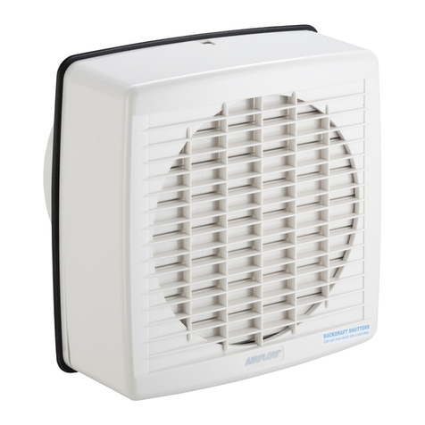
  9. Airflow ICONsmart 15 Operating instructions

Airflow ICONsmart 15 Operating instructions

All electrical installation must be carried out by an
approved electrician in accordance with Part “P” U.K.
Building Regulations and to the latest I T standards, or
the appropriate regulations in the country of installation.
The iCONsmart 15 requires a 110V—240V 50/60 Hz
supply.
The iCONsmart is IPX5 rated and therefore it is suitable
for mounting in bathrooms (in Zone 1 and 2).
For fans mounted in Zones 1 & 2 as defined in BS
7671:2018, additional protection must be provided by an
RCD not exceeding 30mA as well recommends having
an AFDD.
Smart Fan Installation
and Operation Guide
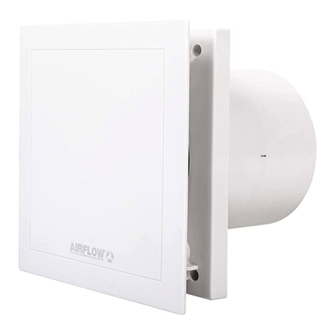
iCONsmart 15 - 72687221
Fan Overview
Main Body
IPX Cover
Front Cover
Model ABCDE
iCONsmart 15 194 118 100 72 144
 Bluetooth connection
to smart device
 Set flow rates
 Change room name
 15 minute overrun
These include: Timer Module (TM) functionality
that can be unlocked via a code (on a scratch
card), Humidity Timer (HT), Motion Sensor Timer
(MST) or a combination of all three (MSHT).
These modules are available separately and can
be fitted at the time of installation or retro-fitted.
(MST)
Front Side
(HT)
60000316—Issue 1 05/19
1. nsure selected power source being used is
isolated.
2. Front cover iris leaves must be in the fully
closed position.
3. Remove fixing screw from bottom of front
cover. (Fig.4)
4. Hold main body, turn the front cover
anticlockwise . Note front cover position for
re-assembly purposes. Lift cover off. (Fig.1/4)
5. Undo the locking screw in the middle of the
IPX cover. Lift IPX cover off. (Fig. 5)
Screw position
Locking screw
(If you have purchased a module, refer to module
instructions now.)
6. Fix sealing grommet supplied into the cable
entry hole. (Fig. 6)
7. Pierce grommet to allow the mains cable to be
fed through whilst maintaining seal integrity.
8. Offer up supply cable to fan. Cut to length needed.
9. Position fan so cable entry and fixing holes align
with those on mounting surface. Feed through
cable and fix fan. (Fig. 6)
10. Wire fan to supply cable, referring to electrical
installation guide. (Page 5)
11. Using cable clamp provided, secure mains cable
into place.
12. To replace IPX cover. Line up the L and R
symbols on the main body of the fan (Fig. 6) with
the L and R symbols on the IPX cover, (Fig .7).
Lightly press IPX cover onto main body.
13. Refit the locking screw, checking the IPX cover
is secure.
Cable ntry
Hole
Mains Terminal
Fixing Holes
Cable Clamp
14. Position front cover over IPX cover in same
orientation as it was removed. Lightly press
front cover onto fan and rotate clockwise up
to stop. Refit fixing screw. (Fig. 8)
iCONsmart comes with flow sensing
technology to a tomatically overcome d ct
system press res.
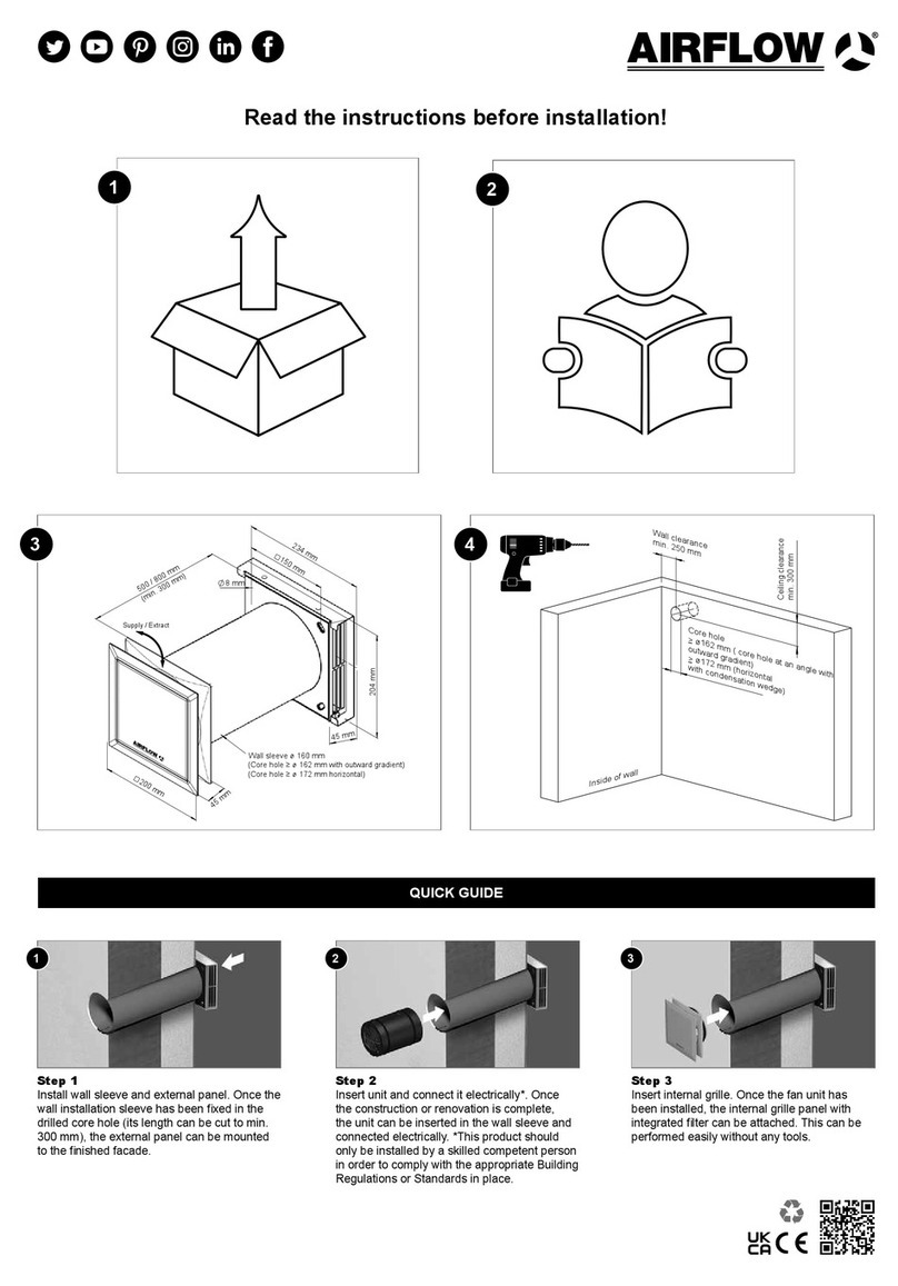
Prepare Wall or Ceiling
The iCONsmart can be installed into a wall or
ceiling.
When recessing fans in the ceiling, a plywood
support (min 18mm thick) should be mounted
between the ceiling joists. Fans should not be
fitted to unsupported plasterboard. (See Fig. 3,
Page 4)
1. Mark out and drill a spigot hole to suit 100mm
diameter rigid ducting.
2. Make provision for the electric supply cable
and wall plugs / appropriate fittings using the
main body as a template. Level using guides
below the L and R symbols. (see Fig. 6, page 7)
3. Fit the wall plugs provided or fixings as
appropriate for the surface.
Page 2 of 16
Page 7 of 16 Page 8 of 16
Page 4 of 16
Page 5 of 16 Page 6 of 16
Electrical Installation
Fig. 1
Fig. 2
Back
Mod le Controls
iCONsmart has several features included as
standard, and can also be fitted with digital micro
modules to give a range of extra control options.
Standard Feat res
 Commission / Notify
NIC IC of install
 Keep 3 month rolling
log of fan switch-on
time and power usage
 Flow rate sensor
Page 3 of 16
Fig. 3
Installation
Fig. 4
Fig. 5
Fig. 6
Screw
L and R Symbols
L Symbol R Symbol
Fig. 7
Fig. 8
Switch Live Wiring
Basic Wiring
(TM)
ØA B
D
ØC
Important: Switches for fans should be selected and
sited in accordance with BS 7671:2018.
(MSHT) - Part No: 72687227
Warranty
Airflow guarantees the iCONsmart and
iCONsmart modules for 5 years from date of
purchase against faulty material or workmanship.
Applicable to units installed and used in the
UNIT D KINGDOM.
Warranty covers the fan, not the reinstallation of
this if required. In the event of any defective parts
being found, Airflow Developments Ltd reserves
the right to repair, or at our discretion replace
without charge, provided the unit:
1. Has been installed in accordance with the
fitting and wiring instructions supplied with
each unit.
2. Has not been connected to an unsuitable
electrical supply.
3. Has not been subjected to misuse, neglect
or damage
4. Has not been modified or repaired by any
person not authorised by Airflow
Developments Ltd.
Airflow Developments shall not be liable for any
loss, injury or other consequential damage, in the
event of a failure of the equipment or arising from,
or in connection with, the equipment excepting
only that nothing in this condition shall be
construed as to exclude or restrict liability for
negligence. Full details at airflow.com/terms
This warranty does not in any way affect any
stat tory or other cons mer rights.
Maintenance
SAF TY FIRST: ALWAYS ISOLAT TH FAN
UNIT FROM TH POW R SUPPLY B FOR
DOING ANY WORK ON TH FAN / MODUL .
When installed by a competent installer,
according to user instructions, the iCONsmart
range is completely safe. The materials used do
not constitute a hazard.
Cleaning
Fan and ducting should be inspected and cleaned
on a regular basis to maintain fan performance.
The external housing of the fan can be wiped with
a damp cloth.
Do not use household cleaners containing abra-
sives. Cleaning of the internal parts such as the
impeller should be carried out by using a soft
brush. Never clean any parts of the fan assembly
by immersing in water or using a dishwasher.
Disposal
Do not dispose of with household waste.
Please recycle where facilities exist.
Check with your local authority for recycling advice.
Best Practise Recommendations
To avoid the backflow of condensation into the
fan in ceiling installations Airflow recommends
fitting a condensation trap to the outlet duct of the
fan.
Where flexible ducting is used the diameter must
be maintained and it is good ventilation practice
that the ducting is extended to a minimum of 90%
its possible length in order to maintain the best
possible air flow.
Page 9 of 16
Page 10 of 16 Page 11 of 16 Page 12 of 16
nsure that flexible duct connections are not over
tightened to the spigots. To maximise the air flow
rigid ducting should be used where possible. The
fan and ducting should be installed in accordance
with the requirements of the Domestic Ventilation
Compliance Guide, part of Part F of the Building
Regulations.
Where flexible ducting is used ensure it is pulled
to 90% of its full length.
Page 13 of 16 Page 14 of 16 Page 15 of 16 Page 16 of 16
App Control and Set p
First Time Use
When the iCONsmart is first powered on, you will
hear the initial reset for 10-15 seconds. This is
normal and will also occur if the fan is reset.
 Home — From this page you can activate the
fan, boost as well as view the installed/
unlocked modules
 Room Health — Shows the live state of the
room on a graph with temperature against
humidity. This requires a module with
humidity function (HT or MSHT) for access.
This graph will show a blue circle
representing the optimum ‘Health Zone’ which
the room should stay within. Too far in the top
right will cause condensation, damp and
mould. Too far in the bottom left can lead to
respiratory problems.
 Usage Data — The iCONsmart stores a 3
month rolling log of power use, time-on and
humidity levels (if you have the a module with
humidity functionality).
 Settings — Contains all adjustable settings
from the setup and more: Setting Flow Rate,
Fan Name, Unlock Timer functionality and all
module parameters.
Home
Room Health
Usage Data
Settings
Do not place the fan near direct heat sources,
e.g. radiant heaters, or where the temperature
can exceed 40°C (104°F).
(TM) - Part No: 72687224 (Scratch card)
(HT) - Part No: 72687225
(MST) - Part No: 72687226
+
To activate the iCONsmart and to set it up:
1. Download and install the ‘myAirflow’ app from
the App Store or Google Play Store to your
device.
2. Open the app, ensuring Bluetooth is enabled
on your device.
3. Follow the intuitive setup process shown on
screen.
This includes setting the flow rate, fan naming
and module settings, (if installed).
Individual installation instructions are supplied
with each module.
Other manuals for ICONsmart 15

1

This manual suits for next models

1

Other Airflow Fan manuals

Airflow iCON 30 Installation guide

Airflow

Airflow iCON 30 Installation guide

Airflow Uno hab Operating manual

Airflow

Airflow Uno hab Operating manual

Airflow Uno hab User manual

Airflow

Airflow Uno hab User manual

Airflow Duplexvent Flexi DV1600 User manual

Airflow

Airflow Duplexvent Flexi DV1600 User manual

Airflow iCON eco15 Installation guide

Airflow

Airflow iCON eco15 Installation guide

Airflow 72687117 Installation guide

Airflow

Airflow 72687117 Installation guide

Airflow QT 150HT User manual

Airflow

Airflow QT 150HT User manual

Airflow AIROVENT MEV WH4B Operation manual

Airflow

Airflow AIROVENT MEV WH4B Operation manual

Airflow Uno hab Manual

Airflow

Airflow Uno hab Manual

Airflow AIROVENT MEV WH4H CENTRAL EXTRACT User manual

Airflow

Airflow AIROVENT MEV WH4H CENTRAL EXTRACT User manual

Airflow QuietAir QT 120T User manual

Airflow

Airflow QuietAir QT 120T User manual

Airflow CE100D User manual

Airflow

Airflow CE100D User manual

Airflow iCONstant T User manual

Airflow

Airflow iCONstant T User manual

Airflow Aventa AV100B Installation guide

Airflow

Airflow Aventa AV100B Installation guide

Airflow MV150 PECO User manual

Airflow

Airflow MV150 PECO User manual

Airflow QuietAir QT 100T User manual

Airflow

Airflow QuietAir QT 100T User manual

Airflow 7005A User manual

Airflow

Airflow 7005A User manual

Airflow AIR 125-R User manual

Airflow

Airflow AIR 125-R User manual

Airflow QuietAir 100 User manual

Airflow

Airflow QuietAir 100 User manual

Airflow Aura Smart User manual

Airflow

Airflow Aura Smart User manual

Airflow DV 90 SE R Specification sheet

Airflow

Airflow DV 90 SE R Specification sheet

Airflow Duplexvent MULTI-N User manual

Airflow

Airflow Duplexvent MULTI-N User manual

Airflow Duplexvent BV400 Operating instructions

Airflow

Airflow Duplexvent BV400 Operating instructions

Airflow Aria 100B Installation guide

Airflow

Airflow Aria 100B Installation guide

Popular Fan manuals by other brands

CFM TBF120 Installation & maintenance instructions

CFM

CFM TBF120 Installation & maintenance instructions

Daikin FWP CT Technical manual

Daikin

Daikin FWP CT Technical manual

AERMEC Omnia HL N Series Use and installation  manual

AERMEC

AERMEC Omnia HL N Series Use and installation manual

Noaton 11132WW FORNAX Instructions for use

Noaton

Noaton 11132WW FORNAX Instructions for use

Casablanca Hampshire owner's manual

Casablanca

Casablanca Hampshire owner's manual

Progress Lighting EF200D installation manual

Progress Lighting

Progress Lighting EF200D installation manual

Emerson CFDR Series owner's manual

Emerson

Emerson CFDR Series owner's manual

German pool EFS-3616 user manual

German pool

German pool EFS-3616 user manual

Ebmpapst A4D350-AA06-02 operating instructions

Ebmpapst

Ebmpapst A4D350-AA06-02 operating instructions

Oriental motor ORIX MRS18V2 operating manual

Oriental motor

Oriental motor ORIX MRS18V2 operating manual

Vornado PIVOT3 owner's guide

Vornado

Vornado PIVOT3 owner's guide

Sealey HVD42B instructions

Sealey

Sealey HVD42B instructions

Lumirama NORMA 9173-015-SN installation guide

Lumirama

Lumirama NORMA 9173-015-SN installation guide

Ruck Ventilatoren EMIX Series Assembly instruction

Ruck Ventilatoren

Ruck Ventilatoren EMIX Series Assembly instruction

Lian-Li UNI FAN SL RGB installation guide

Lian-Li

Lian-Li UNI FAN SL RGB installation guide

Paul CLIMOS F 200 Original operating instructions

Paul

Paul CLIMOS F 200 Original operating instructions

Mitsubishi Electric LGH-F300RVX2-E installation instructions

Mitsubishi Electric

Mitsubishi Electric LGH-F300RVX2-E installation instructions

Vent-Axia Lo-Carbon Minivent B Installation and wiring instructions

Vent-Axia

Vent-Axia Lo-Carbon Minivent B Installation and wiring instructions

manuals.online logo
manuals.online logoBrands
  • About & Mission
  • Contact us
  • Privacy Policy
  • Terms and Conditions

Copyright 2025 Manuals.Online. All Rights Reserved.