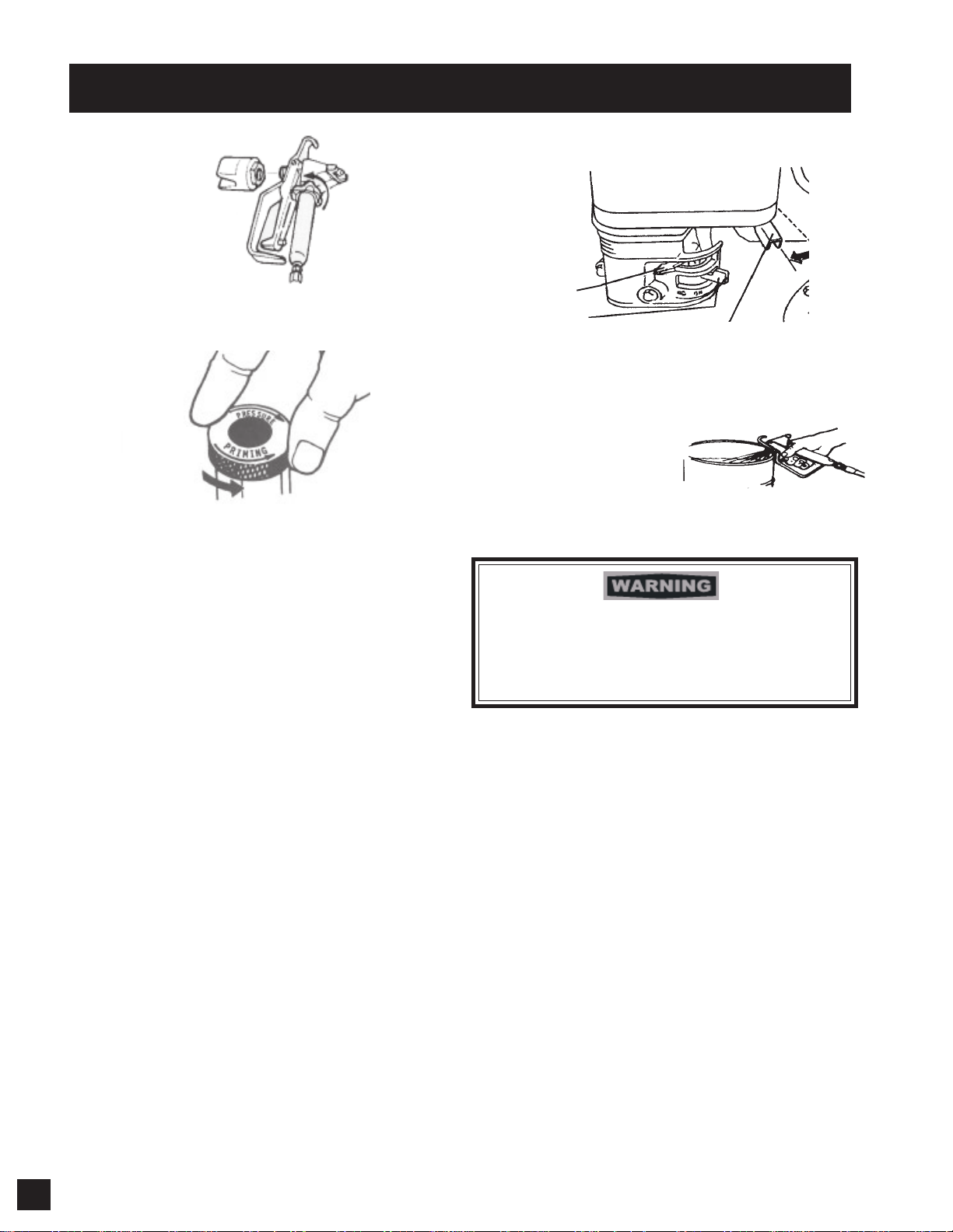
AIRLESSCO Sure Stripe 3300 User manual

SERVICE/OPERATION MANUAL
SURE STRIPE 3300
AIRLESS LINE STRIPER
SURE STRIPE 3300
AIRLESS LINE STRIPER
Form No. 001-436 January 19, 2004
Manufactured by: AIRLESSCO BY DUROTECH CO. P.O. Box 8006, Moorpark, CA 93020-8006 Ship to: 5397 Commerce Ave., Moorp ark, CA 93021
Tel: 805-523-0211 Fax: 805-523-1063

Copyright © 2004, Airlessco by Durotech, All rights reserved. All specifications are subject to change without notice.

Introduction
Sure Stripe 3300 Specifications 1
Safety Warnings 2
Getting Started
Flushing 6
How to Flush 7
Setting Up 8
Starting Up 9
Pressure Relief Procedure 11
Repairs/Maintenance Instructions
Line Striping Operation 12
Airlessco 007X & XL Gun Repairs 14
Spray Gun Techniques 15
Spray Gun Operations 17
Line Striping Tip Charts 18
Troubleshooting 19
Low Spray Pressure Test 20
Inspection & Replacement of
Control Head 21
Replacement of Diaphram 21
Inspection & Replacement of
Control Valve, Ball & Seat 22
Inspection & Replacement of
Suction Valve 22
Inspection & Replacement of
Discharge Valve 23
Pressure Calibration 23
Replacement of Oil Seal 24
TABLE OF CONTENTS
Product Diagrams & Parts List
Airlessco Gun Components 13
Pump Head Assembly 25
Bearing House & Diaphragm 26
Handle Assembly Attachment 27
Gun Assembly Attachment 27
Gun Assembly 28
Throttle Assembly 28
Gun Holder Assembly 29
Frame Assembly 30
Swivel Wheel Assembly 31
Suction Assembly 31
○○○○○○○
○○○○○○○○○○○
○○○○○○○
○○○○○○
○○○○○○○○
○○○○○○○○○○○○○○○○
○○○○○○○○○○○○○
○○○○○○○○○○○
○○○○○○○○○○○○○○
○○○○○○○○○○
○○○○○○○○○○○○○○
○○○○○
○○○○○○○○○○○○○○○
○○○○○○○○○○○○○○○○○○○○
○○○○○○○○○○○○○○○○○
○○○ ○○○○○○○○○○○○○○○○
○○○○○○○○○○○○○○○○○○
○○○○○○○○
○○○ ○○○○○○○
○○○
○○○○○○○○○○
○○○○○○○○○○○
○○○ ○○○○○○○
○○○○○○○○○○○○○○○
○○○ ○○○○○
○○○○○○○○○○○○○○○○○
○○○○○○○○
○○○○○○○○
○○○○○○○○○○○○○○○○
○○○○○○○○○○○○○○○
○○○○○○○○○○○○
○○○○○○○○○

Maximum Pressure: 2500 psi
Output .7 Gallons Per Minute
Tip Size 1 gun - Up to 0.023"
2 guns - Up to 0.015"
Engine - 5.5 hp Honda Overhead Cam
SureStripe 3300 Specifications
The affordable Sure Stripe 3300 is
small, compact, easy to use and quick
to clean. It's balance and light weight
make it ideal for a one-man
operation.
Even changing colors is a breeze.
Stripe with water-based paints made
for traffic lines or athletic feilds.
Release the fun and use as a mobile
paint sprayer to paint walls,
buildings, or to cover graffitti.
The professional quality spray gun is
mounted on a multi-position spray
arm. The swivel wheel model can
release the front wheel when striping
curves and circles. It's buile to last
featureing a heavy-duty frame and
large pneumatic tires. This makes for
smooth, straight lines even on bumpy
athletic field surfaces.
AIRLESSCO SURE-STRIPE 3300
INTRODUCTION
Before operating this unit, read and follow all safety warnings and instructions
related to the usage of this equipment. READ, LEARN, and FOLLOW the
Pressure Relief Procedure on Page 11 and understand all warnings on
pages 2,3,4 & 5.
IMPORTANT WARNING !!
HANDLE THIS UNIT AS YOU WOULD A LOADED FIREARM!!
High pressure spray can cause extremely serious injury.
OBSERVE ALL WARNINGS!
All Service Procedures to be performed by an Authorized Airlessco Service Center ONLY.
NO MODIFICATIONS or alterations of any Airlessco Equipment or part is allowed.
1

SAFETY WARNINGS
Fluids under high pressure from spray or leaks can penetrate the skin and cause extremely serious
injury, including the need for amputation.
• NEVER point the spray gun at anyone or any part of the body.
• NEVER put hands or fingers over the spray tip. Do not use a rag or any other material over your fingers. Paint will
penetrate through material and into the hand.
• NEVER try to stop or deflect leaks with your hand or body .
• NEVER try to "blow back" paint, this is not an air spray sprayer.
•ALWAYS have gun tip guard in place when spraying.
•ALWAYS lock gun trigger when you stop spraying.
•ALWAYS remove tip from the gun to clean it.
•ALWAYS follow the PRESSURE RELIEF PROCEDURE, as shown on page 11, before cleaning or removing the
spray tip or servicing any system equipment.
•ALWAYS Be sure equipment safety devices are operating properly before each use.
•ALWAYS tighten all fluid connections before each use.
MEDICALTREATMENT
If any fluid appears to penetrate your skin, get EMERGENCY CARE AT ONCE. DO NOT TREAT AS A SIMPLE CUT.
* Go to an emer gency room immediately.
* Tell the doctor you suspect an injection injury .
* Tell him what kind of material you were spraying with and have him read NOTE TO PHYSICIAN.
HIGH PRESSURE SPRAY CAN CAUSE EXTREMELY SERIOUS INJURY.
OBSERVEALLWARNINGS. THIS SPRAYER IS FOR PROFESSIONAL USE ONLY.
MEDICALALERT- Airless Spray Wounds NOTETO PHYSICIAN:
If any fluid appears to penetrate your skin, get Injection in the skin is a traumatic injury.
EMERGENCYMEDICALCAREAT ONCE. DO It is important to treat the injury surgically
NOT TREAT AS A SIMPLE CUT. Tell the doctor as soon as possible. DO NOT DELAY treatment
exactly what fluid was injected. Have him read to research toxicity. Toxicity is a concern with
the following "NOTE TO PHYSICIAN". some exotic coatings injected directly into the
bloodstream. Consulation with a plastic surgeon or
reconstructive hand surgeon may be advisable.
INJECTIONHAZARD
GENERAL PRECAUTIONS
• NEVER alter equipment in any manner. • NEVER smoke while in spraying area.
• NEVER spray highly flammable materials. • NEVER use around children.
• NEVER allow another person to use sprayer unless they are thoroughly instructed on safety use and
given this operators manual to read.
•ALWAYS wear a spray mask, gloves and protective eye wear while spraying.
•ALWAYS ensure fire extinquishing equipment is readily available and properly maintained.
NEVER LEAVE SPRAYER UNATTENDED WITH PRESSURE IN THE SYSTEM. FOLLOWPRESSURE RELIEF
PROCEDURES ON PAGE 11.
2

TIP GUARD
ALWAYS have the tip guard in place on the spray gun while spraying. The tip guard alerts you to the injection hazard and helps
prevent accidentally placing your fingers or any part of your body close to the spray tip.
SPRAYTIPSAFETY
Use extreme caution when cleaning or changing spray tips. If the spray tip clogs while spraying, engage the gun safety latch
immediately.
•ALWAYS follow the PRESSURE RELIEF PROCEDURE and then remove the spray tip to clean it.
• NEVER wipe off build up around the spray tip.
•ALWAYS remove tip & tip guard to clean AFTER pump is turned off and the pressure is relieved by following the
PRESSURE RELIEF PROCEDURE.
KEEP CLEAR OF MOVING PARTS
Keep clear of moving parts when starting or operating the sprayer. Do not put your fingers into any openings to avoid
amputation by moving parts or burns from hot parts.
Precaution is the best insurance against an accident.
When starting the engine, maintain a safe distance from moving parts of the equipment.
Before adjusting or servicing any mechanical part of the sprayer, follow the PRESSURE RELIEF PROCEDURE, and remove the
ignition cable from the spark plug to prevent accidental starting of the sprayer.
ALWAYS INSPECT SPRAYING AREA
•ALWAYS keep spraying area free from obstructions.
•ALWAYS make sure area has good ventilation to safely remove vapors and mists.
•NEVER keep flammable material in spraying area.
•NEVER spray in vicinity of open flame or other sources of ignition.
•Spraying area must be at least 20 ft. away from the spray unit.
SPRAY GUN SAFETY
•ALWAYS set safety lock on the gun in "LOCKED" position when not in use and before servicing or cleaning.
•NEVER remove or modify any part of the gun.
•ALWAYS REMOVE SPRAY TIP when cleaning. Flush unit with LOWEST POSSIBLE PRESSURE.
•ALWAYS check operation of all gun safety devices before each use.
•Be very careful when removing the spray tip or hose from gun. A plugged line contains fluid under pressure. If the tip or line
is plugged, follow the PRESSURE RELIEF PROCEDURE as outlined on page 11.
SAFETY WARNINGS
Keep all labels on the unit clean and readable. Replacement labels are available from the manufacturer .
LABELING
Hazardous fluid or toxic fumes can cause serious injury or death if splashed in eyes or on skin, inhaled or swallowed. Know
the hazards of the fluid you are using. S tore & dispose of hazardous fluids according to manufacturer, local, state & national
guidelines. ALWAYS wear protective eyewear, gloves, clothing and respirator as recommended by fluid manufacturer .
TOXIC FLUID HAZARD
3

AVOID COMPONENT RUPTURE
This sprayer operates at 3000 psi (205 bar). Always be sure that all components and accessories have a
maximum working pressure of at least 3000 psi to avoid rupture which can result in serious bodily injury
including injection and property damage.
• NEVER leave a pressurized sprayer unattended to avoid accidental operation of it which could result in serious
bodily injury.
•ALWAYS follow the PRESSURE RELIEF PROCEDURE whenever you stop spraying and before adjusting,
removing or repairing any part of the sprayer.
• NEVER alter or modify any part of the equipment to avoid possible component rupture which could result in
serious bodily injury and property damage.
• NEVER use weak, damaged or non-conductive paint hoses. Do not allow kinking or crushing of hoses or allow
it to vibrate against rough, sharp or hot surfaces. Before each use, check hoses for damage and wear and ensure
all fluid connections are secure.
• REPLACE any damaged hose. NEVER use tape or any device to mend the hose.
• NEVER attempt to stop any leakage in the line or fittings with your hand or any part of the body. Turn off the
unit and release pressure by following PRESSURE RELIEF PROCEDURE on page 11.
•ALWAYS use approved high pressure fittings and replacement parts.
•ALWAYS ensure fire extinquishing equipment is readily available and properly maintained.
SAFETY WARNINGS
GROUNDING
Ground the sprayer and other components in the system to reduce the risk of static sparking, fire or
explosion which can result in serious bodily injury and property damage.
Alwaysground allof thesecomponents:
•Sprayer: Connect a ground wire and clamp (supplied) to a true earth ground.
•FluidHose: use only grounded hoses.
•Spraygunordispensingvalve: grounding is obtained through connection to a properly
grounded fluid hose and pump.
•Objectbeingsprayed: according to your local code.
• All solvent pails used when flushing should only be metal pails which are conductive.
Once each week, check electrical resistance of hose (when using multiple hose assemblies, check
overall resistance of unpressurized hose must not exceed 29 megohms (max) for any coupled length
or combination of hose lengths. If hose exceeds these limits, replace it immediately.
Never exceed 500 Ft. (150 m.) overall combined hose length to assure electrical continuity.
Do not use halogenated solvents in this system. The prime valve, 2 gun manifold and most
airless guns have aluminum parts and may explode. Cleaning agents, coatings, paints or
adhesives may contain halogenated hydrocarbon solvents. DON'T TAKE CHANCES!
Consult your material suppliers to be sure. Some of the most common of these solvents are:
Carbontetrachloride,Chlorobenzene, Dichloroethane, Dichloroethyl Ether, Ethylbromide,
Ethylchloride, Tethrachloethane.Alternate valves and guns are available
if you need to use these solvents.
4

PREVENT STATIC SPARKING FIRE/ EXPLOSIONS
ALWAYS be sure all equipment and objects being sprayed are properly grounded. Always ground sprayer, paint
bucket and object being sprayed. See "grounding" on page 4 for detailed grounding information.
Vapors created when spraying can be ignited by sparks. To reduce the risk of fire, always locate the sprayer at least
20 feet (6 m.) away from the spray area. Do not plug in or unplug any electrical cords in the spray area, this can
create sparks when there is any chance of igniting vapors still in the air. Follow the coating & solvent manufacturers
safety warnings and precautions.
Use only conductive fluid hoses for airless applications. Be sure gun is grounded through hose connections. Check
ground continuity in hose & equipment. Overall (end to end) resistance of unpressurized hose must not exceed 29
megohms for any coupled length or combination of hose length. Use only high pressure airless hoses with static wire
approved for 3000 psi.
WHEN SPRAYING & CLEANING WITH FLAMMABLE PAINTS OR PAINT
THINNERS:
1.When spraying with flammable liquids, the unit must be located a minimum of 25 feet away
from the spraying area in a well ventilated area. Ventilation must be sufficient enough to
prevent the accumulation of vapors.
2. To eliminate electrostatic discharge, ground the spray unit, paint bucket and spraying object.
Use only high pressure airless hoses approved for 3000 psi which is conductive.
3. Remove spray tip before cleaning gun and hose. Make contact of gun with bucket and spray
without the tip in a well ventilated area, into the grounded steel bucket.
4. Never use high pressure in the cleaning process. USE MINIMUM PRESSURE.
5. Do not smoke in spraying/cleaning area.
GAS ENGINE PRECAUTIONS
Locate unit 25 feet away from spray area in well ventilated area.
• NEVER operate in closed buildings unless exhaust is piped outside.
• NEVER allow hose to lay against engine mufflers or hot parts.
• NEVER refill fuel tank while engine is hot or is running.
Important: United States Government safety standards have been adopted under the
Occupational Safety & Health Act. These standards, particularly the General Standards, Part
1910, & the Construction Standards, part 1926 should be consulted.
FLUSHING
Reduce the risk of injection injury, static sparking or splashing by following the specific cleaning procedure on page 7.
•ALWAYS follow the PRESSURE RELIEF PROCEDURE on page 11.
•ALWAYS remove the spray tip before flushing. Hold a metal part of the gun firmly to the side of a metal pail and
use the lowest possible fluid pressure during flushing.
•NEVER use cleaning solvents with flash points below 140º F. Some of these are: acetone, benzene, ether,
gasoline and naphtha. Consult your supplier to be sure.
•NEVERsmoke in the spraying/cleaning area.
SAFETY WARNINGS
5

1. New Sprayer
Your Airlessco unit was factory tested in an antifreeze solution which was left in the pump. Before
using oil-base paint, flush with mineral spirits only. Before using water-base paint flush with soapy
water, then do a clean water flush.
2. Changing Colors
Flush with a compatible solvent such as mineral spirits or water .
3. Changing from water-base to oil-base paint.
Flush with soapy water, then mineral spirits.
4. Changing from oil-base to water-base paint.
Flush with mineral spirits, followed by soapy water, then do a clean water flush.
5. Storage
Oil-basepaint: Flush with mineral spirits.
Water-basepaint: Flush with water, then mineral spirits and leave the pump, hose and gun filled
with mineral spirits. For longer storage, use mixture of mineral spirits and motor oil
(half & half). Shut off the sprayer, follow Pressure Relief Procedure on page 11 to
relieve pressure and make sure prime valve is left OPEN.
6. Start up after storage
Before using water-base paint, flush with soapy water and then do a clean water flush. When using
oil-base paint, flush out the mineral spirits with the material to be sprayed.
FLUSHING
Read prior to using your sprayer
6

FIGURE 2
FIGURE 1
REMOVE
SPRAY
TIP
FIGURE 3
FIGURE 4
MAINTAINFIRM
METAL TO METAL
CONTACT BETWEEN
GUN AND CONTAINER
1. Be sure the gun safety latch is engaged and there is
no spray tip in the gun. Refer to Fig. 1. Refer to your
separate instruction manual provided with your gun
on its safety features and how to engage safety latch.
2. Pour enough clean, compatible solvent into a large,
empty metal pail to fill the pump and hoses.
3. Place the suction tube into the pail or place the pail
under the pump.
4. Turn the pressure control knob to low pressure. Refer
to Fig. 2.
5. Open the prime valve to the open - "Priming Position".
This will allow an easy start. Refer to Fig.2.
6. Turn the engine ON/OFF switch to ON.
7. Move the choke to the closed position as per Fig.3.
8. Move the throttle lever slightly to the left as per Fig.3.
9. Turn the fuel valve ON as per Fig. 3. Pull the start rope.
Pull the engine over against compression stroke and then
let the rope rewind slowly into the starter . Pull firmly and
rapidly to start the engine. Do NOT drop the rope. Hold
onto the handle while rewinding, or the rope may rewind
improperly and jam the assembly. If the engine does not
start, open the choke half way. If the engine floods, open
the choke all the way and continue cranking.
10.After the engine is warm, gradually open the choke
lever, increase the RPM of engine by moving throttle
all the way to the left. Close the prime valve. Refer to
Fig. 2
11. Point the gun into the metal pail and hold a metal part of
the gun firmly against the pail Refer to fig. 4 .
12. Disengage the gun safety latch and squeeze the gun
trigger. At the same time, slowly turn the pressure
control knob clockwise just enough to move liquid at
low pressure.
13. Allow the pump to operate until clean solvent comes
from the gun.
14. Release the trigger and engage the gun safety latch.
15. If you are going to start spraying, place the pump or
suction tube into the supply container . Release the
gun safety latch and trigger the gun into another
empty, metal container, holding a metal part of the gun
firmly against the metal pail (Fig. 4) and force the
solvent from the pump and hose. When paint starts
coming from the gun, turn pressure control knob to
minimum pressure, place prime valve in prime (open)
position and engage the gun safety latch.
16. If you are going to store the sprayer , remove the
suction tube or pump from the solvent pail force the
solvent from the pump and hose. Engage the gun
safety latch and refer to the "Storage" Procedure on
page 6. Step 5.
17. Whenever you shut off the sprayer follow the
Pressure Relief Procedure warning on page 11.
HOW TO FLUSH
To reduce the risk of static sparking, which can
cause fire or explosion, always hold a metal
part of the gun firmly against the metal pail
when flushing. This also reduces splashing.
Refer to Fig.4.
ChokeLever
FuelValve ThrottleLever
7
CONTROL
VALVE

SETTING UP
3. Check the Engine Oil Level.
a. Unscrew the oil fill plug. The dipstick is attached to
the plug.
b. Without threading the plug into place, check to be
sure the oil is up to the top mark on the dipstick.
c. If oil is needed, refer to
engine manual.
NOTE: Unit is shipped
WITH OIL in engine
and clutch.
5. Fill the Fuel Tank.
Fuel spilled on a hot surface can cause a fire or explosion and cause
serious bodily injury and property damage. Always shut off the engine
and let it cool before filling the tank, and carefully follow Steps a-c below,
being sure not to spill any fuel.
a. Close the fuel shutoff valve.
b. Use only clean, fresh, well-known brands of
unleaded regular grade gasoline.
c. Remove the fuel cap and fill tank, Be sure the air
vent in the fill cap is not plugged so fuel can flow to
the carburetor, then replace the cap.
6. Flush the sprayer.
See "Flushing". Your new pump was factory
tested in an ant-freeze solution and it must be flushed
before using.
NOTE: Prior to striping, see Linestriping
Operations (page 4) for correct gun arm set up,
to get proper sized lines.
1. Attach handle assembly.
Refer to Figure 5. Complete steps a - d for both
sides of the handle.
a. Slide plate (Item 1) over clamp (Item 2).
b. Place clamp with plate attached over frame
(Item 4), so that the holes in the clamp are in
alignment with the holes in the frame.
c. Put the handle (Item 5) down through the
holes in the clamp and frame.
d. Set handle to desired height and tighten the
screw (Item 3) so that the plate is snug
against the frame.
2. Install the gun arm assembly.
Refer to Figure 6.
a. Choose which side of the frame to mount the
gun arm.
b. Complete Steps a - c from attaching the handle
assembly (above), except mounting the gun
arm instead of the handle.
c. Set gun arm to desired height and tighten the
adjustable handle (Item 3) until the plate is
snug against the frame. Note: The adjustable
handle can be ratchet by lifting up on the
handle.
Plate
Clamp
Adjustable Handle
Frame
Gun Arm
Upper Limit
Lower Limit
FIGURE 5 FIGURE 6
FIGURE 7
FIGURE 8
Plate
Clamp
Screw
Frame
Handle
4. Check Clutch Oil Level.
a. Complete steps a-c of Check the Engine Oil Level,
except using the clutch dipstick.
8

STARTING UP
The control valve sets the prime or pressure position
as well as the spraying pressure. When the valve is
fully counter-clockwise the unit is in the prime position.
As the control valve is turned clockwise, the unit’s
output pressure to the gun is gradually increased until
the control valve is fully clockwise and the unit is at
2500 psi.
FOLLOW THE "PRESSURE RELIEF
PROCEDURES" ON PAGE 11 WHENEVER
YOU:
- are instructed to relieve pressure
- stop spraying
- checking or servicing any of the system equipment.
- install or clean the spray tip.
HANDLE THE SPRAY SYSTEM AS YOU
WOULDALOADED FIREARM!!
2. Prepare the Material
a. Prepare the material according to the
manufacturer's material recommendations.
b. Place the suction tube into the material
container.
4. Prime the Pump
a. Allow pump to operate until paint comes from gun.
b. Release the trigger and engage the gun safety latch.
c. Turn Control Valve to the prime position (Fully CCW)
ensuring the pressure is released from the system.
d. Install spray tip onto gun.
f. Turn Control Valve clockwise to the desired spray
pressure (max. 2500 psi).
g. Disengage the gun safety lock and you are ready to
start spraying.
To stop the unit in an emergency or before
performing any service or maintenance
procedurefollowthePressure Relief
Procedure on page 11 to relieve the
fluidpressure.
3. Starting the Sprayer
(see Fig. 6 above)
a. Control Valve must be open to the priming
position or fully counterclockwise.
b. Pressure Control Knob must be in the low
pressure position.
c. Follow the procedure under "How to Flush",
page 7, Steps 6 through 12.
5. Adjusting the Pressure
a. Turn the Control Valve clockwise to increase
pressure and counterclockwise to decrease pressure.
b. Always use the lowest pressure necessary to
completely automize the material.
c. If more coverage is needed use a larger tip rather than
increasing the pressure.
d. Check the spray pattern. The tip size and angle
determines the pattern width and flow rate.
If you spray into the paint bucket,
always use the lowest spray pressure and
maintain firm metal to metal contact between
gun and container. See page 7, Fig. 4.
Operating the sprayer at higher
pressure than needed wastes material, causes
early tip wear and shortens sprayer life.
9
1. Learn how to operate the control valve.
FIG. 6

6. Cleaning a Clogged Tip.
Always follow the Pressure Relief Procedure
before performing any service or
maintenance procedure.
Neverholdyour body,fingers,orhandin
frontofthespray tip when cleaning or
checkingit foraclearedtip. Alwayspoint
thegunfowardorintoawasteconainer
whencheckingtosee if thetipiscleared
orwhenusing aself-cleaningtip.
a. Follow the Pressure Relief Procedure.
b. Clean the front of the tip frequently (with a tooth-
brush only) during the day to keep material from
building up and clogging the tip.
c. To clean and clear a tip if it clogs, refer to the
separate instruction manual received with your gun
and nozzle.
There is an easy way to keep the outside of
the tip clean from material build-up:
Everytime you stop spraying, for even a minute, lock
the gun and submerge the gun nozzle into a small bucket
of thinner compatible with the material sprayed.
Thinner will dissolve the build up of paint on the
outside of the tip, tip guard and gun much more
effectively than if the paint dries out completely.
Witha Cloggedstandardflattip -cleanonly
afterthetipis removed fromthegun.
FollowthePressure ReliefProcedure
7. When shutting Off the Sprayer
a. Whenever you stop spraying, even for a short break,
follow the Pressure Relief Procedure.
b. Clean the tip and gun as recommended by your
separate gun instruction manual.
c. Flush the sprayer at the end of each work day if the
material you are spraying is waterbased, or if it could
harden in the sprayer overnight. See "Flushing" page 6
and 7. Use a compatible solvent to flush, then fill the
pump and hoses with an oil based solvent such as
mineral spirits.
d. For long term shutdown or storage, refer to page 6.
STARTING UP
10

PRESSURE RELIEF PROCEDURE
Tighten all fluid connections securely before each use. High pressure fluid can dislodge a loose coupling
or allow high pressure spray to be emitted from the coupling and result in an injection injury or serious
bodily injury.
HOSES
2. Turn engineoff.
3. Disengage safety latch &
trigger gun to relieve residual
fluidpressure. Hold metalpart of thegun in
contactwith groundedmetal pail.
4. Re-engage gun safety latch
1. Engage gun safety latch. Refer to
separateinstructionmanual provided
with your gun on its safety features
and how to engage safety latch. 5. TurnControlValve (Prime/Pressure
Relief Valve)asshown open (priming)
torelieve fluid pressure.
To avoidpossibleseriousbodilyinjury,includinginjection, alwaysfollowthis procedure
wheneverthe sprayeris shut off,whenchecking orservicing it,wheninstalling orchanging
thetips, whenever youstopspraying or whenyou are instructedtorelieve the pressure.
IF THE SPRAY TIP OR HOSE IS CLOGGED:
Follow Step 1 through 5 above. Expect paint splashing into the bucket while relieving pressure during
Step 5. If you suspect that pressure hasn't been relieved due to damaged prime/pressure relief valve or
other reason, engage gun safety latch and take your sprayer to an authorized Airlessco Service Center for
service. *Always follow recommended pressure & operating instructions.
NEVER use a damaged hose which can result in hose failure or rupture and cause an injection injury
or other serious bodily injury or bodily damage. Before each use, check entire hose for cuts, leaks,
abrasions or bulging of cover, or damage or movement of couplings. If any of these conditions exist,
replace the hose immediately. Never use tape or any device to try to mend the hose as it cannot contain
the high pressure fluid. NEVER ATTEMPT TO RECOUP THE HOSE. High pressure hoses are not
recoupable. Help prevent damage to the hose by handling and routing carefully. Do not move the
sprayer by pulling it with the hose.
Use only a hose that has a spring guard. The spring guard helps protect the hose from kinks or other dam-
age which could result in hose rupture and cause an injection injury.
11

c. Tighten locking nut and retest gun triggers for
proper function.
Note: There is an additional cable adjustment
where the cable attaches to the gun holder
assembly. Use only if the gun trigger
adjustment is insufficient.
5. Miscellaneous Operations
a. CURBS: Adjust gun to desired height and turn
swivel head towards curb.
b. WIDE STRIPES: Install wider fan striping tips
and raise the gun height to achieve the desired
width line. Also angle guns slightly towards each
other to get an even coat of paint.
c. STENCILS: Install standard spray tip on the
outer gun. Remove this gun from the gun holder
and spray out the stencils.
d. STANDARD PAINTING: Same as stencils, but
use additional paint hose as required.
LINE STRIPING OPERATION
1. Choose handle location
The choices are, installing the handle opposite
of the single wheel assembly (standard set up)
or placing the handle directly over the single
wheel assembly. The handle location is really a
matter of personal preference, however having
the handle away from the single wheel assembly
allows for easier loading/unloading from a van.
2. Choose the gun arm position
There are six holes in the frame for mounting
the gun arm. In a standard set up (handle away
from the single wheel assembly), the gun arm
would be mounted in one of the two mounting
holes near the single wheel. This allows for an
easier visual check for straight line striping and
for basic arc striping. The mounting holes under
the handle are usually used when the handle has
been placed over the single wheel. Experiment
with different combinations to find the set up
that you prefer.
3. Setting up the guns
a. Ensure that striping tips are in the guns.
b. Pick a tip size for the desired line width.
Example: a 217ST tip for a four inch line.
c. Place gun into the gun holder, so that the top
of the taper on the gun handle is flush with
the edge of the gun holder.
d. Set gun height for the desired line width.
Adjust height by loosening the small black
handle on the gun holder assembly and slide
the gun arm to the correct height. Now
tighten the handle. This will require some
experimentation to find the correct height. It
is suggested that tape, or some other method
is used to mark the height of commonly used
settings.
e. Set spacing between the two guns by
loosening the black handle on the gun arm.
Slide to the desired width and tighten.
f. Attach the swivel heads to the guns if
painting curbs or wide stripes.
g. Angle the guns slightly forward. This allows
the spray pressure from the guns to help
blow dirt and debris out of the path of the
new stripes.
4. Cable TensionAdjustment
Once the handle and gun arm assemblies are set up to
the preferred positions, pressurize the unit and trigger
each gun to ensure that they activate and release
correctly. If not, adjust the cable tension as follows:
a. Locate the adjustment knobs on the base of the
gun trigger, where the cable connects to the gun
trigger assembly.
b. Loose the locking nut and move the adjusting
screw until the slack has been removed from the
cable.
12

SPRAY GUN PARTS LIST
007X & 007XL SPRAY GUNS
Item No. Part No. Description Item No. Part No. Description
1
2
3
4
5
6
7
8
9
9a
10
11
12
13
14
561-001
560-xxx
561-025
561-026
120-023
120-005
120-035
120-037
120-011
120-033
120-022
120-046
120-002
120-045
120-020
Rev-Guard
Rev-Tip
Rev-Tip Seal-metal
Rev-Tip Seal-O-ring
Screw (3)
Guard
Valve Seat Complete
Valve Ball with Holder
Valve Spring Unit
Seals PTFE (2)
Trigger Pin
Washer (2)
Gun Head
Retainer Pin (2)
Retainer
15
16
17
18
19
20
21
22
23
24
25
26
27
120-021
120-056
120-048
120-055
120-049
120-082
120-090CX
120-090FX
120-088
120-087
115-019
120-044
120-085
032-012
Nut
Washer
Safety Latch or Trigger Lock
Wave Washer
Retaining Ring
Seal
Filter-Complete-Coarse
Filter-Complete-Fine
Spring
Handle Complete 007X
Connector
Trigger
Handle with Swivel 007XL
F/G Thread Adaptor
13

1. Lock gun trigger.
2. Turn Rev-Tip handle 180 degrees.
3. Disengage trigger lock and trigger gun into pail.
4. If the Rev-Tip handles appears locked
(resists turning) loosen the retaining
nut. Then handle will now turn easily.
5. Engage trigger lock and return
handle to the spray position.
ADJUSTING SPRAY GUN
Hold gun with trigger locked (25) and push trigger against the
lock (17). Then adjust nut (15) so that the retainer (14) will
move freely back and forth approximately 1/32" to allow valve
spring unit (9) to seat the valve ball (8).
IMPORTANT: Readjust nut (15) periodically for
wear of valve seat (7) and valve ball (8); otherwise,
leakagewilloccur.
TO REPLACE THE VALVE BALL HOLDER (8)
KIT #2-007
3 Tip Washers 1 Valve Seat (7)
1 Valve Ball Holder (8) 2 Seals-PTFE (9a)
REPLACING THE VALVE SPRING UNIT (9)
KIT#3-007
3 Tip Washers 1 Valve Seat (7)
1 Valve Ball Holder (8) 1 Valve Spring Unit (9)
When removing and replacing valve seat (7), hold
the trigger (25) in the open position so that the valve
ball (8) is lifted off the valve seat. Failure to lift the
ball off the seat will result in a scratched leaky valve.
3. Unscrew valve ball (8) together with the brass part of
the assembly (9). Do not pull on the parts or the
packing may get damaged.
4. Unscrew the valve ball (8) from the brass part of the
assembly (9).
Reassembling is done in reverse sequence. Screw the new
valve ball with holder (8) into the brass part (9).
Tighten valve ball and brass part on threaded end
of the shaft by hand until you feel a positive stop.
Do not tighten with a wrench since this could
result in breaking the shaft.
Note: Itis recommended thatyouchange thevalve
seat (7) and valve ball (8) at the same time.
1. Repeat dismantling procedure as outlined above
under Steps 1 through 3.
2. Unscrew nut (15), remove retainer (14) with retainer
pins (13) and push shaft of the valve spring unit (9)
out of the gun head (12).
3. Clean gun head (12) bore with solvent and small
brush. Do not use any sharp objects to scrape away
dried paint, as they would cause leakage around the seal.
Reassembling is done in reverse sequence.
IMPORTANT: When reassembling, install valve
spring unit (9) with spring loose.
CLEANING 007 SPRAY GUN
Immediately after the work is finished, flush the gun out
with a solvent. Brush pins (13) with solvent and oil them
lightly so they will not collect dried paint.
TO REMOVE CLOGS- REVERSIBLE TIP
Push firmly into gun head by hand. Install retainer pins 13),
retainer (14) and nut (15) loosely onto valve spring unit
(9). By hand turn front of valve spring unit clockwise,
tightening the valve spring unit until you feel a positive
stop. At that point, continue tightening the valve spring
another 1/8 turn expanding the PTFE seals against body
of gun.
CLEANING FILTER
To clean the filter, use a brush dipped in as appropriate
solvent. Change or clean filters at least once a day .
Some types of latex may require a filter change after
four hours of operation.
007X & 007XL SPRAY GUN
GUN SAFETY LATCH
IN LOCKED
POSITION
GUN
SAFETY
LATCH
RELEASED
Attachspray guntohose andtightenfittings securely.
Setthegun safetylatch.(Alsomay becalled gunsafety
lock)Thegun safetylatchshould alwaysbeset whenthe
gunis notbeing triggered.
CLOGGED FLAT TIP
Should the spray tip become clogged, relieve pressure
from hoses by following the "Pressure Relief Procedure"
in Machine Manual, secure the gun with safety lock (17),
take off Guard, take out the tip, soak in appropriate
solvent & clean with a brush. (Do not use a needle or
sharp pointed instrument to clean the tip. The tungsten
carbide is brittle and can chip.)
Reverseto
Unplug
Spray Position Shown
Do not tighten beyond 1/8 turn as this can result in
breaking the valve spring unit shaft. Continue
reassembly and adjustment as described above.
Dismantling:
1. Unscrew Rev-Guard and remove spray tip and seal.
2. Unscrew valve seat (7) with 1/2" socket wrench.
14

SPRAY TECHNIQUE - REGULAR AIRLESS SPRAYING
The closer the spray gun is held to the work, the
thicker the paint is deposited and the faster the gun
must be moved to prevent sags and runs. Holding
the gun too far from the work will cause excessive
fog, overspray, and a thin and grainy coat.
Good Spray Gun Technique is at the core of any
spray paint operation. Operator skill and efficiency
is as important as good equipment and good paint.
Good spray technique is a skill that can be quickly
learned by following these simple instructions.
If you are not familiar with spraying techniques,
we recommend that you study this section of your
manual and practice the proper technique on pieces
of cardboard or a suitable surface.
RIGHT WRONG
Equal spray distance
Equal amount of paint
Equal spray distance
Hold gun straight
up and down
TILTED GUN ANGLE
causes uneven paint coating
Shorter spray distance
Excessive paint spray
Insufficient paint spray
Longer spray distance
CORRECT DISTANCE
CORRECT GUN ANGLE
Hold the spray gun 12 - 15 inches away from the work surface and keep it perpendicular (straight) to the
surface. Move the spray gun parallel to the work and at a right angle to the surface.
WRONG
Move the gun at a steady rate in order to apply a
good coverage. The wet coat should be just under
the thickness at which a run or sag will occur. Slow
gun movement or gun held too close will result in an
overly wet or thick wet or thick coat coverage that
is likely to run or sag.
Do not wave the spray gun. This waving is called
arching. Instead, hold the spray gun at a 12 to 15
inch distance perpendicular from the work.
RIGHT
correct
distance
correct
distance
Keep even distance to surface.
15

SPRAY TECHNIQUE - REGULAR AIRLESS SPRAYING
"Inside" and "outside" corners can be sprayed.
Aim the spray gun toward the center of the corner.
The spray pattern is divided in half, and the edges
of the spray pattern on both walls are the same.
Always use the lowest pressure possible to obtain
desirable results.
Test the spray pattern on a piece of cardboard or
other surface.
It is important to "trigger" the gun after gun movement
(arm movement) has started and release trigger (shut
gun off) before gun movement ends. Gun movement is
always longer than actual paint (spray) stroke. In that
manner, even blending and uniform paint coat thickness
is achieved over the entire surface. When the gun is in
motion as the trigger is pulled, it deposits an even
amount of paint.
Overlap the previous pass by half the width of the
spray pattern. Aim at the bottom of the previous pass.
Spray with uniform strokes from left to right and
from right to left, holding stroke speed, distance,
lapping, and triggering as uniform as possible.
Adjust pressure control knob so that paint is com-
pletely atomized from the spray gun. Insufficient
pressure will result in "tailing".
Too much pressure will result in excess fog and
overspray, excessive tip wear, and increased
sprayer wear and tear.
16

AIRLESS SPRAY GUN OPERATION
DEFECTS CAUSE CORRECTION
Coarse spray Low pressure Increase the pressure.
Excessive fogging High pressure Reduce the pressure to satisfactory
(overspray) pattern distribution.
Material too thin Use less thinner.
Pattern too wide Spray angle too large Use smaller spray angle tip.
Pattern too narrow Spray angle too small Use larger spray angle tip. (If coverage
is OK, try tip in same nozzle group)
Too much material Nozzle too large Use next smaller nozzle.
Material too thin
Pressure too high Reduce pressure.
Too little material Nozzle too small Use next larger nozzle.
Material too thick
Thin distribution in Worn tip Change for new tip.
center of pattern Wrong tip Use nozzle with a narrow spray angle.
"horns"
Thick skin on work Material too viscous Thin cautiously.
Application too heavy Reduce pressure and/or use tip in next
smaller nozzle group.
Coating fails to Material too viscous Thin cautiously.
close & smooth over
Spray pattern irreg- Orifice clogged Clean carefully.
ular, deflected Tip damaged Replace with new tip.
Craters or pock Solvent balance Use 1 to 3% "short" solvents & the
marks, bubbles remainder "longsolvents". (This is
most likely to happenwith material of
low viscosity, lacquers etc.)
Clogged screens Debris in paint Clean screen
Coarse paint pigments Use coarse gun filter screen.
Incompatible paint Use coarser screen for larger orifice tips.
mixture & thinners. If thinner was added, test to see if a drop
on top of paint mixes or flattens out on
the surface. If not, try different thinner in
fresh batch of paint.
17
Table of contents
Other AIRLESSCO Construction Equipment manuals