AirMan PDS185S-6E1 User manual

www.discount-equipment.com
Discount-Equipment.com

Discount-Equipment.com is your online resource for commercial and industrial
quality parts and equipment sales.
Locations:
Florida (West Palm Beach): 561-964-4949
Outside Florida TOLL FREE: 877-690-3101
Need parts? Check out our website at www.discount-equipment.com
Can’t find what you need?
Click on this link: http://www.discount-equipment.com/category/5443-parts/ and fill out
the request form.
Please have the machine model and serial number available in order to help us get
you the correct parts. One of our experienced staff members will get back to you with
a quote for the right part that your machine needs.
We sell worldwide for the brands: Genie, Terex, JLG, MultiQuip, Mayco, Toro/Stone,
Diamond Products, Magnum, Airman, Mustang, Power Blanket, Nifty Lift, Atlas Copco,
Chicago Pneumatic, Allmand Brothers, Essick, Miller Spreader, Skyjack, Lull, Skytrak,
Tsurumi, Husquvarna/Target, Whiteman-Concrete/Mortar, Stow-Concrete/Mortar, Baldor,
Wacker, Sakai, Snorkel, Upright, Mi-T-M, Sullair, Neal, Basic, Dynapac, MBW, Weber,
Bartell, Bennar Newman, Haulotte, Ditch Runner, Blaw-Knox, Himoinsa, Best, Buddy,
Crown, Edco, Wyco, Bomag, Laymor, Terremite, Barreto, EZ Trench, Takeuchi, Basic, Bil-
Jax, Curtis, Gehl, Heli, Honda, ICS/PowerGrit, Puckett, Waldon, ASV, IHI, Partner, Imer,
Clipper, MMD, Koshin, Rice, Gorman Rupp, CH&E, Cat Pumps, Comet, General Pump,
Giant,AMida, Coleman, NAC, Gradall, Square Shooter, Kent, Stanley, Tamco, Toku, Hatz,
Kohler, Robin, Wisconsin, Northrock, Oztec, Toker TK, Rol-Air, Small Line, Wanco, Yanmar
Discount-Equipment.com

Preface
This service manual explains about the cautions for maintenance jobs and is to serve a
guide for the electric system, and troubleshooting for service personnel. Fundamental
matters and other things already mentioned in the “Instruction Manual” and the “Parts
Catalogue” are omitted to avoid duplication. Therefore, for the operation and handling of
this unit, we request you to refer to the instruction manual and caution plates, and
further for the structure and components of the unit, please refer to the “Parts
Catalogue” separately to be supplied with the unit.
If you should find any description which does not coincide with the instruction manual
and parts catalog, we request you to make sure to start the job after clarifying it.
Service personnel is required to safely take quick and proper countermeasures as well
as to use correct technology of maintenance in case of field services and periodical
maintenance. It is important that service personnel should have proper and sufficient
knowledge about the structure and function of the unit and should be well familiar with
such technique mentioned in them.
Regarding the part numbers mentioned in this manual, we request you to refer to the
Parts catalogue separately supplied together with the unit, because the parts numbers
in this manual are sometimes changed.
Copies of this service manual are intended to be distributed to limited numbers
of our customers. The unauthorized reproduction or distribution of this service
manual is prohibited.
Discount-Equipment.com

Table of Contents
1. Specification -------------------------------------------------------------------------------------- 1-1
1.1 Specifications ----------------------------------------------------------------------------------------------------------- 1-1
1.2 Set Value ----------------------------------------------------------------------------------------------------------------- 1-2
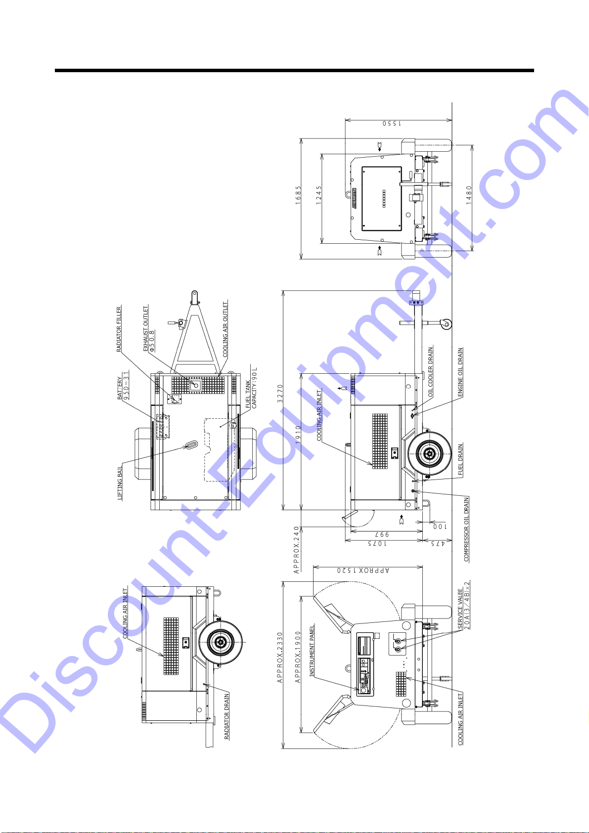
1.3 Outline Drawing -------------------------------------------------------------------------------------------------------- 1-3
1.4 Internal Components and Part Names ---------------------------------------------------------------------------- 1-5
1.5 Instrument Panel ------------------------------------------------------------------------------------------------------- 1-7
1.5.1 Indicator lamp ------------------------------------------------------------------------------------------------------- 1-8
1.6 Capacity Control Device ---------------------------------------------------------------------------------------------- 1-9
1.6.1 Auto idle control (purge control) -------------------------------------------------------------------------------- 1-10
1.6.2 Adjustment of auto idle control (purge control) and correction of engine speed -------------------- 1-11
1.7 Piping Diagram --------------------------------------------------------------------------------------------------------- 1-12
1.8 Fuel Piping --------------------------------------------------------------------------------------------------------------- 1-13
2. Maintenance --------------------------------------------------------------------------------------- 2-1
2.1 Cautions for Overhauling --------------------------------------------------------------------------------------------- 2-1
2.1.1 Precautions before starting work ------------------------------------------------------------------------------- 2-1
2.1.2 Disassembly and reassembly ----------------------------------------------------------------------------------- 2-1
2.2 Tightening Torque ----------------------------------------------------------------------------------------------------- 2-2
2.2.1 General bolts and nuts tightening torque --------------------------------------------------------------------- 2-2
2.2.2 Tightening torque of such important quality parts as bolts and nuts ----------------------------------- 2-3
2.3 How to Adjust Regulator --------------------------------------------------------------------------------------------- 2-6
2.4 Change of Element in Fuel Pre-filter ------------------------------------------------------------------------------ 2-7
2.5 Change Oil Separator ------------------------------------------------------------------------------------------------- 2-8
2.6 Change O-ring of Unloader ------------------------------------------------------------------------------------------ 2-9
2.7 Change O-ring of Auto-relief Valve and Vacuum Relief Valve ---------------------------------------------- 2-11
2.8 Maintenance and Adjustment of Pressure Control Valve ---------------------------------------------------- 2-12
2.9 Change of Pellet assembly of By-pass Valve ------------------------------------------------------------------- 2-13
2.10 Air Bleeding in Fuel Line --------------------------------------------------------------------------------------------- 2-14
2.11 Clean Inside of Fuel Tank -------------------------------------------------------------------------------------------- 2-14
2.12 Clean Drain Separator (Option: With aftercooler only) -------------------------------------------------------- 2-15
2.13 Values of Various Adjustments of Engine ------------------------------------------------------------------------ 2-15
3. Electric System ----------------------------------------------------------------------------------- 3-1
3.1 Electronic Control System of Engine ------------------------------------------------------------------------------ 3-1
3.1.1 Electronic control system ---------------------------------------------------------------------------------------- 3-1
3.1.2 Acceleration control ----------------------------------------------------------------------------------------------- 3-2
3.1.3 Diesel particulate filter (DPF) ----------------------------------------------------------------------------------- 3-3
3.1.4 DPF regeneration control ---------------------------------------------------------------------------------------- 3-4
3.1.5 Preheating control ------------------------------------------------------------------------------------------------- 3-7
3.2 Emergency Controller ------------------------------------------------------------------------------------------------- 3-8
3.2.1 Emergency controller --------------------------------------------------------------------------------------------- 3-13
3.3 Engine Controller (ECU) --------------------------------------------------------------------------------------------- 3-17
3.4 Alternator ----------------------------------------------------------------------------------------------------------------- 3-24
3.5 Starter --------------------------------------------------------------------------------------------------------------------- 3-26
3.6 Starter / Glow Plug Relay -------------------------------------------------------------------------------------------- 3-27
3.7 EGR Valve Relay ------------------------------------------------------------------------------------------------------ 3-28
3.8 Solenoid Valve (SV1) for Starting Unloader and Purge /
Solenoid Valve (SV2) for Aftercooler Drain: Option ----------------------------------------------------------- 3-29
3.9 Engine Oil Pressure Switch (for emergency stops) ------------------------------------------------------------ 3-29
3.10 Fuel Air-bleeding Electromagnetic Pump ------------------------------------------------------------------------ 3-30
3.11 Discharge Temperature Sensor / Water temperature Sensor ----------------------------------------------- 3-30
Discount-Equipment.com

Table of Contents
3.12 Pressure Sensor (for intake negative pressure /
service pressure and regulator secondary pressure) --------------------------------------------------------- 3-31
3.13 Fuel Meter (Display) --------------------------------------------------------------------------------------------------- 3-31
3.14 Sending Unit ------------------------------------------------------------------------------------------------------------- 3-32
3.15 Air filter Differential Pressure Switch ------------------------------------------------------------------------------ 3-32
3.16 Electronic Control Engine Component ---------------------------------------------------------------------------- 3-33
3.16.1 Supply pump ------------------------------------------------------------------------------------------------------- 3-34
3.16.2 Rail ------------------------------------------------------------------------------------------------------------------- 3-34
3.16.3 Rail pressure sensor --------------------------------------------------------------------------------------------- 3-34
3.16.4 Injector -------------------------------------------------------------------------------------------------------------- 3-35
3.16.5 Water temperature sensor (ECU) ---------------------------------------------------------------------------- 3-35
3.16.6 Water temperature sensor (Gauge) -------------------------------------------------------------------------- 3-35
3.16.7 Engine oil pressure switch ------------------------------------------------------------------------------------- 3-35
3.16.8 Crank speed sensor --------------------------------------------------------------------------------------------- 3-36
3.16.9 Cam speed sensor ----------------------------------------------------------------------------------------------- 3-36
3.16.10 New air temperature sensor ----------------------------------------------------------------------------------- 3-36
3.16.11 Intake air temperature sensor -------------------------------------------------------------------------------- 3-36
3.16.12 Intake air throttles ------------------------------------------------------------------------------------------------ 3-37
3.16.13 EGR valve --------------------------------------------------------------------------------------------------------- 3-38
3.16.14 EGR (Intake/Exhaust) pressure sensor -------------------------------------------------------------------- 3-38
3.16.15 EGR gas temperature sensor --------------------------------------------------------------------------------- 3-38
3.16.16 Exhaust manifold temperature sensor ---------------------------------------------------------------------- 3-39
3.16.17 Diesel particulate filter (DPF) differential pressure sensor --------------------------------------------- 3-39
3.16.18 Diesel particulate filter (DPF) intermediate/inlet temperature sensor ------------------------------- 3-40
3.16.19 Fuel temperature sensor --------------------------------------------------------------------------------------- 3-40
4. Troubleshooting --------------------------------------------------------------------------------- 4-1
4.1 Repairing Procedures ------------------------------------------------------------------------------------------------- 4-1
4.1.1 Safety caution ------------------------------------------------------------------------------------------------------- 4-1
4.1.2 Caution during failure diagnosis -------------------------------------------------------------------------------- 4-1
4.1.3 How to use the failure diagnosis ----------------------------------------------------------------------------- 4-2
4.2 Failures of Compressor and Engine ------------------------------------------------------------------------------- 4-3
4.2.1 At start-up, starter rotates slowly ------------------------------------------------------------------------------- 4-3
4.2.2 Starter turns, but engine will not start ------------------------------------------------------------------------- 4-3
4.2.3 Engine revolutions will drop before rises up to rated pressure ----------------------------------------- 4-4
4.2.4 Engine will not turn to meet rated revolutions --------------------------------------------------------------- 4-5
4.2.5 Minimum speed not available even upon no-load operation ---------------------------------------- 4-6
4.2.6 Safety valve bursts out during unloaded operation -------------------------------------------------------- 4-6
4.2.7 Oil mixed found in delivery air ----------------------------------------------------------------------------------- 4-7
4.2.8 Water found mixed in discharge air (Aftercooler type) ------------------------------------------------ 4-7
4.2.9 Discharge air is insufficient -------------------------------------------------------------------------------------- 4-8
4.2.10 Purge control operation will not start even if AUTO IDLE (purge control) switch is pressed -- 4-9
4.2.11 Even when the pressure at consumer’s side drops, it will not recover from
purge control operation -------------- 4-10
Discount-Equipment.com

Table of Contents
4.3 Operation of Emergency Switch ------------------------------------------------------------------------------------ 4-11
4.3.1 Discharge temperature indication lamp glows and engine stops --------------------------------------- 4-11
4.3.2 Engine oil pressure indication lamp glows and engine stops ------------------------------------------- 4-12
4.3.3 Engine water temperature indication lamp glows and engine stops ----------------------------------- 4-13
4.4 Others --------------------------------------------------------------------------------------------------------------------- 4-14
4.4.1 Residual pressure lamp lights on and engine will not be able to start -------------------------------- 4-14
4.4.2 Indicator lamps will not glow, but engine stops ------------------------------------------------------------- 4-14
4.5 Explanation of Trouble Diagnosis ---------------------------------------------------------------------------------- 4-15
4.6 Engine Trouble Diagnosis Function ------------------------------------------------------------------------------- 4-17
4.6.1 Engine trouble diagnosis ----------------------------------------------------------------------------------------- 4-17
4.6.2 List of diagnostic trouble codes (DTC) ------------------------------------------------------------------------ 4-21
4.6.3 Trouble diagnosis tool (SMARTASSIST-Direct) ------------------------------------------------------------ 4-23
5. References ----------------------------------------------------------------------------------------- 5-1
5.1 Consumable Parts and Electrical Appliances ------------------------------------------------------------------- 5-1
5.2 Engine Wiring Diagram ----------------------------------------------------------------------------------------------- 5-3
Discount-Equipment.com

1. Specification
1-1
1.1 Specifications
Item unit
●Weight・Mass
Overall length in.(mm) 128.7(3,270)
Overall length (Bonnet only) in.(mm) 75.2(1,910)
Overall width in.(mm) 66.3(1,685)
Overall height in.(mm) 61.0(1,550)
Net dry mass lb(kg) 2,050( 930)
Operating mass lb(kg) 2,271(1,030)
●Compressor
Free air delivery cfm(m3/min) 185(5.2)
Working pressure psi(MPa)[bar] 100(0.69)[ 6.9]
Pressure of pressure control valve psi(MPa)[bar] 58(0.40)[ 4.0]
Burst pressure of safety valve psi(MPa)[bar] 150(1.03)[10.3]
Ambient conditions: temperature °F(℃) 5 to 104(-15 to +40)
Ambient conditions: altitude yd(m) Less than 1,640(1,500)
●Engine
Type YANMAR 4TNV88C-DHKS
Rated output (Gross) hp/min-1
(kW/min-1) 47.6/3,000(35.5/3,000)
Rated output (Net) hp/min-1
(kW/min-1) 45.6/3,000(34.0/3,000)
Fuel consumption g/kW・h 248
Rated RPM min-1 3,000
RPM at unload conditions min-1 1,350
Net dry mass lb(kg) 441(200)
●Lubricating oils
Engine oil capacity (H/L level) gal.(L) 1.95/0.90(7.4/3.4)
Compressor oil capacity
(including receiver tank and oil cooler
etc.)
gal.(L) 3.59(13.6)
Compressor oil capacity to be filled
Ambient temperature
:
5°F to 104°F (-15
℃
to +40
℃
)
HULS : ANDEROL 3032
MOBIL : RARUS SHC 1024
TEXACO:SYN-STARDE32
Coolant capacity gal.(L) 1.80(6.8)
Fuel tank capacity gal.(L) 23.8(90)
●Fuel consumption ratio
(for reference only)
At purge operation gal./Hr(L/Hr) 0.40(1.5)
At no load gal./Hr(L/Hr) 0.74(2.8)
At 50% gal./Hr(L/Hr) 1.29(4.9)
At 70% gal./Hr(L/Hr) 1.64(6.2)
At full load gal./Hr(L/Hr) 2.38(9.0)
Discount-Equipment.com

1. Specification
1-2
1.2 Set Value
Item unit
●Emergency stop devices
Actuating temperature of discharge
temperature switch °F(℃) 248(120)
Actuating temperature of water
temperature switch °F(℃) 230(110)
Actuating pressure of oil pressure
switch psi(MPa)[bar] 7.1(0.049)[0.49]
●Warning devices
Actuating temperature of discharge
temperature switch °F(℃) 239(115)
Actuating temperature of water
temperature switch °F(℃) 221(105)
Battery failure When not charged
Actuating pressure of air filter
indicator psi(kPa)[bar] 0.9(6.23)[0.0623]
●Set value
Pressure control valve psi(MPa)[bar] 58(0.40)[ 4.0]
Actuating pressure of safety valve psi(MPa)[bar] 150(1.03)[10.3]
Unload starting pressure psi(MPa)[bar] 100(0.69)[ 6.9]
Time for starting purge mode
operation
(At AUTO IDLE operation mode)
sec 5 to 60
(Set at 10 sec. ex. works)
●Engine RPM
Rated RPM min-1 3,000
RPM at unload min-1 1,350
●Indications of gauges or instruments
during operation
Discharge pressure gauge
(at full load) psi(MPa)[bar] 58 to 100(0.40 to 0.69)[4.0 to 6.9]
Discharge pressure gauge
(at no load) psi(MPa)[bar] 104 to 131(0.72 to 0.90)[7.2 to 9.0]
Discharge pressure gauge
(at purge operation) psi(MPa)[bar] 39 to 73(0.27 to 0.50)[2.7 to 5.0]
Discount-Equipment.com

1. Specification
1-3
1.3 Outline Drawing
Unit:in.
A131026
Discount-Equipment.com

1. Specification
1-4
Unit:mm
A131025
Discount-Equipment.com

1. Specification
1-5
1.4 Internal Components and Part Names
PC13114
No. Description No. Description
1 Instrument panel 16 By-pass valve
2 Service pressure sensor 17 Oil cooler
3 Regulator secondary pressure 18 Oil cooler drain valve
4 Pressure control valve 19 Engine oil drain valve
5 Oil separator 20 Fuel cap
6 Pressure regulator 21 Supply pump
7 Air filter (For compressor air-end) 22 Engine oil filter
8 Vacuator valve (For compressor air-end) 23 Engine oil level gauge
9 Fuel tank 24 Intake negative pressure sensor
10 Sedimenter and pre-filter 25 Compressor oil level gauge
11 Air filter (For engine) 26 Fuel tank drain valve
12 Vacuator valve (For engine) 27 Separator receiver tank drain valve
13 Engine oil filler port 28 Compressor oil filler port
14 Fuel filter 29 Service valve
15 Air-bleeding electromagnetic pump
28 27 26 25 24 23 22 21 20 19 18
1 2 3 4 5 6 7 8 9 10 11 12 13 14 15 16 17
29
Discount-Equipment.com

1. Specification
1-6
PC13113
No. Description No. Description
30 Exhaust pipe 39 Separator receiver tank
31 Radiator 40 Safety valve
32 Reserve tank 41 Discharge pipe
33 Cooling fan 42 Air-end
34 Alternator 43 Coupling
35 Engine 44 Starter
36 Air filter differential pressure indicator
(For compressor air-end) 45 Battery
37 Solenoid valve for starting unloader
(purge) 46 Radiator drain valve
38 Compressor oil filter 47 Diesel particulate filter (DPF)
47 46 45 44 43 42 41
30
31
32 33
34 35 36 37 38 39 40
Discount-Equipment.com

1. Specification
1-7
1.5 Instrument Panel
A130957
Digital monitor
When power is supplied, revolution speed (lamp lighting) is indicated.
●In case that discharge air temperature is below 0°F, “---L” is indicated on screen.
●In case the compressor load factor is more than 50%, “b--H” is indicated on screen.
●The indication of discharge pressure / the compressor load factor is displayed only at the time
of purge driving.
ELLOR CODE switch
When this switch is pushed on while lamp is blinking, it
shows error code. When starter switch is placed to
“STOP”, displayed screen is reset.
AUTO IDLE switch
This switch is used when fuel consumption is
minimized at no load operation. (It functions
when the lamp goes on.)
[ENG.SPEED]
(min-
1
)
[DISCHARGE TEMP.]
(°F)
[WATER TEMP.]
(
°F
)
[HOUR METER]
(Hr)
Push
Push Push Push
[COMPRESSOR LOAD FACTOR]
(%)
[DISCHARGE PRESS.]
(PSI)
Whenever indication selector switch is pushed every time, indication
screen is changed by turns as shown above.
Indication selector switch
Discount-Equipment.com

1. Specification
1-8
1.5.1 Indicator lamp
[Indicator lamp] Turn the starter switch to “RUN” position. Then the lamp goes on.
Item Contents Measures Monitor
GLOW
When starter switch is placed to “RUN”,
the lamp goes on and after preheating is
finished, the lamp will be off. ―
CHARGE
Lamp goes on when alternator is not
charging.
Check wiring
Check alternator
[Warning display] This displays such trouble of less importance when it occurs during operation,
but the unit continues operating.
When any abnormality happens, a ERROR CODE lamp flickers. In this time
when ERROR CODE switch is pressed, a error code will be displayed.
Item Error
code Contents
DISCHARGE TEMP. H
A1 Lamp flickers when the air temperature at the outlet of the
air-end reaches 239°F (115℃).
WATER TEMP. H
A2 Lamp flickers when coolant temperature reaches 221°F (105℃).
COMP. AIR FILTER
A3 It is displays when air filter gets clogged and suction resistance
increases.
[Operating resistance: More than 0.062bar(6.23kPa)]
ENG. AIR FILTER
A4
CHARGE
A5 Belt loosened and/or cut
Faulty generation of alternator
[Emergency display] When any trouble takes place during operation, this displays and it stops as
an emergency stop.
When any abnormality happens, a ERROR CODE lamp flickers. In this time
when ERROR CODE switch is pressed, a error code will be displayed.
Item Error
code Contents
DISCHARGE TEMP. H
E1 It is displays when the air temperature at the outlet of the
air-end reaches 248°F (120℃).
WATER TEMP. H
E2 It is displays when coolant temperature reaches 230°F (110℃).
ENG. OIL PRESS.
E3 It is displays when engine oil pressure drops.
【Function pressure: 7.1psi(0.049MPa)[0.49bar]】
DISCHARGE TEMP.
SENSOR
E6 It is displayed when air temperature sensor at the outlet port of
compressor air-end is disconnected.
WATER TEMP. SENSOR
E7 It is displayed when engine water temperature sensor is
disconnected.
Discount-Equipment.com

1. Specification
1-9
1.6 Capacity Control Device
A131023E
Step Response
Start
Compressed air flows into unloader chamber (A) because solenoid valve for
purge control SV1 is opened at start-up. The pressure in chamber (A) rises
soon to close unloader valve fully and accordingly it can reduce the load at
start-up.
Load operation
After starting, SV1 is closed after automatic unloaded operation, and the air
volume which is sent to chamber (A) increases and decreases according to the
rise and drop of the discharge air pressure and consequently the opening
width of the unloader valve is changed. Further, engine speed (RPM) is
changed by the pressure which PRS1 detects, and it steplessly controls the air
volume in the range from 0 to 100%.
Suction port closing
unload operation
When compressed air pressure exceeds the rated pressure with reduction of
air consumption, PRS1 detects the pressure and it reduces engine speed
(RPM) in proportion to the pressure rise, and it closes unloader valve at the
same time. When compressor air-end becomes vacuum during unload
operation, vacuum noise is caused. To prevent this noise, it opens vacuum
relief valve by detection of secondary pressure of pressure regulator. Thus
high vacuum condition of compressor air-end is prevented.
Purge control unload
operation
When the certain set time (it can be changed.) has passed at lower pressure
than the set negative pressure, detecting the negative pressure inside the
compressor air-end with a pressure sensor PRS2, solenoid valve SV1 opens
and it closes unloader valve. At the same time, it functions to relieve the
compressed air from separator receiver tank to the atmosphere and thus it
lowers the pressure. Thus the compressor power is saved. When air
consumption increases, and the pressure used for load drops below the set
pressure, pressure sensor PRS3 detects it and it disengages the purge control
(SV1 closes) to start full load operation.
Stop
When stopping operation, it opens auto-relief valve to relieve the compressed
air in separator receiver tank to atmosphere, detecting the pressure inside
compressor air-end.
Discount-Equipment.com

1. Specification
1-10
1.6.1 Auto idle control (purge control)
This model is equipped with auto idle control operation mode. This operation mode is recommendable
for such use: not so much air consumption is required and it is used continuously and also power
consumption under unloaded operation is required to be saved. Use this mode, depending upon the
need and demand. For the selection of this mode, switch on“AUTO IDLE”on the operation panel.
Select this operation mode freely, according to required air consumption.
<Procedure>
①During operation, long push (2 seconds) on AUTO IDLE switch (purge control) “1”.
②Then the AUTO IDLE lamp “2” goes on.
③In order to stop this operation mode, push again AUTO IDLE switch “1” and then the lamp “2”
goes out to disengage this purge control.
A130957
Function of auto idle control (purge control)
Function Conditions of AUTO IDLE lamp
①First engine speed drops to the minimum speed by pressure
regulator, owing to reduction of air consumption. Later the
air consumption is reduced further, the unloader valve
gradually closes and intake negative pressure increases. In
this stage, the pressure sensor detects the intake negative
pressure. Then when the intake negative pressure becomes
higher than the set pressure, the AUTO IDLE lamp flickers
at short intervals.
Lamp flickers at short intervals.
②When this condition continues for a certain time, the
solenoid valve functions to start purge mode operation.
Consequently, the pressure inside separator receiver tank
drops and reduces the power of compressor air-end. In this
stage, the AUTO IDLE lamp flickers at longer intervals.
Lamp flickers at longer intervals.
③Next, when the pressure for load down to the purge
releasing pressure owing to the increase of air consumption,
the solenoid valve operation gets “OFF” and it is
transferred to normal operation. In this stage, the AUTO
IDLE lamp goes on.
Lamp goes on.
1
2
Discount-Equipment.com

1. Specification
1-11
1.6.2 Adjustment of auto idle control (purge control) and correction of engine
speed
No. Item Indication Unit Primary set value Range of set values
1 Purge releasing pressure PSI 86 70 to 100
2 Waiting time for transfer to
purge mode operation sec 10 5 to 60
3 Load factor for transfer to
purge mode operation %15 5 to 30
4
The high-speed side
correction
(Full load rotational speed) min-1 100 0 to 200
5
The low-speed side
correction
(Unload rotational speed) min-1 100 0 to 200
<Procedures of adjustment>
When SELECT switch is pressed longer (than 5 seconds), first P. (Purge releasing pressure) is
displayed. Each time SELECT switch is pressed, each indication will be selected. Then each time
it is pressed one time, T. (Waiting time for transfer to purge mode operation) is switched to
b. (Load factor for transfer to purge mode operation) to H. (Full load rotational speed) to L. (Unload
rotational speed), according to the set orders.
[Load factor for transfer
to purge mode operation]
Press three
times after
setting job
is finished.
Press two
times after
setting job
is finished.
[Purge releasing
pressure]
[Waiting time for transfer
to purge mode operation]
Press one
time after
setting job
is finished.
UP DOWN
UP DOWN UP DOWN
[Full load rotational
speed]
[Unload rotational
speed]
Press two
times after
setting job
is finished.
UP DOWN UP DOWN
Press two
times after
setting job
is finished.
Discount-Equipment.com

1. Specification
1-12
1.7 Piping Diagram
PC14063E
Discount-Equipment.com

1. Specification
1-13
1.8 Fuel Piping
PC14001
Discount-Equipment.com

2. Maintenance
2-1
2.1 Cautions for Overhauling
2.1.1 Precautions before starting work
(1) Work to be performed
It is very important to always plan in advance what facilities, tools, instruments, materials, oil, etc.
you will need to use; the exact locations and methods of performing inspection, adjustment, or
disassembly; and the key points of any repair work to be performed.
(2) Care not to spill oil
Use a pan to collect used compressor oil, engine oil when changing the oil or attaching or detaching
an oil line. If a large volume of oil is expected to flow out, make sure to drain any accumulated oil
from the reserve tank, engine oil pan in advance.
[Follow the designated regulations to dispose of compressor oil and engine oil.]
(3) Care when detaching parts
When disassembling a complicated part, put a matching mark to indicate the position of detached
parts for future reference. Make sure that the negative -cable is detached from the battery
terminals before starting repair work.
(4) Use genuine parts
Make sure to use genuine parts when changing parts. Otherwise, it degrades performance and it
shortens machine life.
(5) Tools to be prepared
①Measuring instruments
(e. g. tester, insulation resistance gauge etc.)
②Tools
③Torque wrenches
④Jigs and specialized tools
⑤Sealing tape
⑥Molybdenum sulfide (tube type)
2.1.2 Disassembly and reassembly
①Before removing nylon tubes, hydraulic/fuel hoses, it is necessary to clean the inside of machine
to prevent from entrance of dirt and foreign matters.
②Perform disassembly work in a dust-free location whenever possible.
③When disassembling parts, wash their outer surfaces and place them on a clean sheet of paper or
cloth, taking care not to contaminate or damage them.
④Wash disassembled parts with diesel oil (cleaning solvent) after checking for contamination or
discoloration. However, do not wash rubber parts with diesel oil.
⑤Be careful not to damage disassembled parts, they are precision built.
⑥Replace consumables such as oil seals, O-rings, filters, oil, etc. with new items when reassembling
parts.
⑦Apply “CALTEX MULTIFAK EP1” to O-ring surface. Never coat the sliding portion of oil seal
with grease because it loses sealing effect by stopping screw groove with grease.
⑧ When reassembling parts, place each part in the order of assembly and take care that no parts
are missing or misassembled.
⑨When reassembling an assembled part (set part), be sure to replace it as an assembly.
⑩ Contamination or rusting may occur due to dust or humidity if parts are left in disassembled or
partly disassembled condition for a long time. Therefore, be careful to prevent dust or rust from
affecting parts if you have to leave the repair incomplete for a long period of time.
⑪Check tightening torque and clearance when assembling parts.
⑫Check the direction of rotation, speed, and oil leakage after assembly.
⑬Before starting the machine after disassembly, run it at low idle to check for unusual noises, etc.
to prevent engine or generator damage.
⑦Lithium based all-purpose grease
●CALTEX MULTIFAK EP1
⑧ Diesel oil
⑨Compressor oil
⑩ Cleaning cloths
⑪Literatures (such as manuals etc.)
Discount-Equipment.com
Table of contents
Other AirMan Air Compressor manuals

AirMan
AirMan PDSE900S-4B1 User manual

AirMan
AirMan ResQ Pilot User manual

AirMan
AirMan PDS185S-6C1 User manual

AirMan
AirMan PDS375S-6A1 User manual

AirMan
AirMan C71A-54 User manual

AirMan
AirMan PDS400S-6E1 User manual

AirMan
AirMan PDS185S-5C2 User manual

AirMan
AirMan PDS400S-6C3 User manual

AirMan
AirMan PDS400S-6E1 User manual

AirMan
AirMan PDS100S-6B4 User manual
Popular Air Compressor manuals by other brands

Compass
Compass BLOCK manual

Bostitch
Bostitch BTEC25200 instruction manual

California Air Tools
California Air Tools 20020CR-22060 owner's manual

Bauer
Bauer Mini Verticus Instruction manual and replacement parts list

GEA
GEA HGX34 CO2 T Series Assembly instructions

Craftsman
Craftsman 921.166400 owner's manual