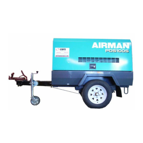
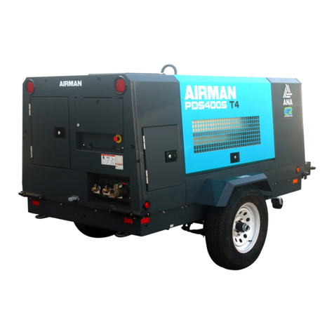
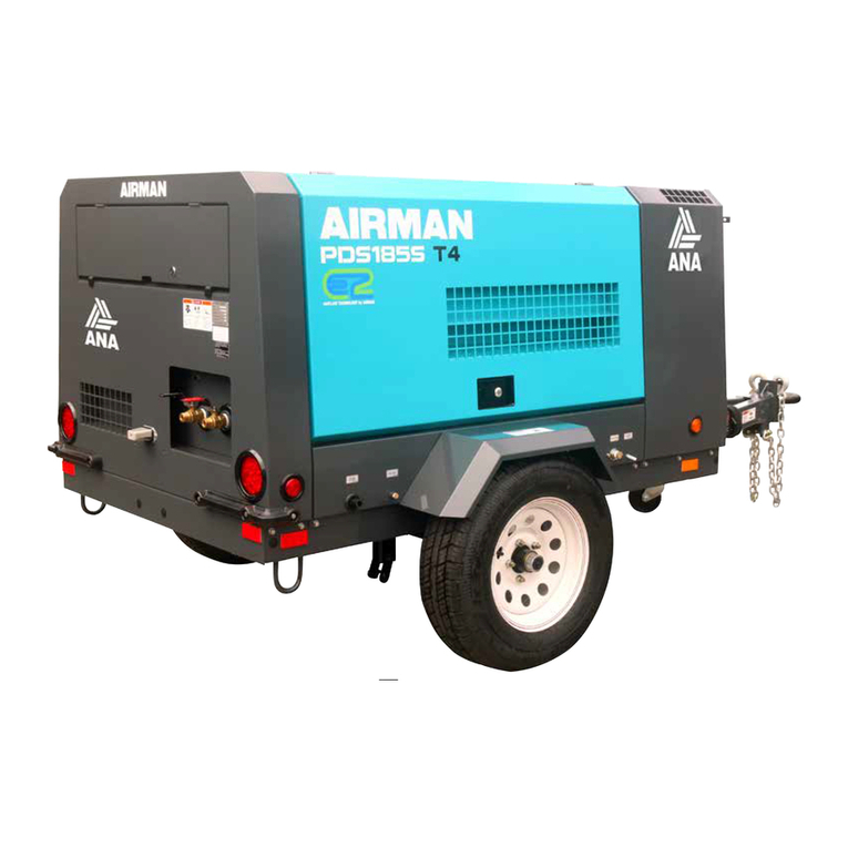
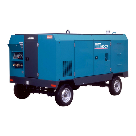
AirMan PDS185S-6C1 User manual

Discount-Equipment.com

Discount-Equipment.com is your online resource for commercial and industrial
quality parts and equipment sales.
Locations:
Florida (West Palm Beach): 561-964-4949
Outside Florida TOLL FREE: 877-690-3101
Need parts? Check out our website at www.discount-equipment.com
Can’t find what you need?
Click on this link: http://www.discount-equipment.com/category/5443-parts/ and fill out
the request form.
Please have the machine model and serial number available in order to help us get
you the correct parts. One of our experienced staff members will get back to you with
a quote for the right part that your machine needs.
We sell worldwide for the brands: Genie, Terex, JLG, MultiQuip, Mayco, Toro/Stone,
Diamond Products, Magnum, Airman, Mustang, Power Blanket, Nifty Lift, Atlas Copco,
Chicago Pneumatic, Allmand Brothers, Essick, Miller Spreader, Skyjack, Lull, Skytrak,
Tsurumi, Husquvarna/Target, Whiteman-Concrete/Mortar, Stow-Concrete/Mortar, Baldor,
Wacker, Sakai, Snorkel, Upright, Mi-T-M, Sullair, Neal, Basic, Dynapac, MBW, Weber,
Bartell, Bennar Newman, Haulotte, Ditch Runner, Blaw-Knox, Himoinsa, Best, Buddy,
Crown, Edco, Wyco, Bomag, Laymor, Terremite, Barreto, EZ Trench, Takeuchi, Basic, Bil-
Jax, Curtis, Gehl, Heli, Honda, ICS/PowerGrit, Puckett, Waldon, ASV, IHI, Partner, Imer,
Clipper, MMD, Koshin, Rice, Gorman Rupp, CH&E, Cat Pumps, Comet, General Pump,
Giant,AMida, Coleman, NAC, Gradall, Square Shooter, Kent, Stanley, Tamco, Toku, Hatz,
Kohler, Robin, Wisconsin, Northrock, Oztec, Toker TK, Rol-Air, Small Line, Wanco, Yanmar
Discount-Equipment.com

Preface
This service manual explains about the cautions for maintenance jobs and is to serve a
guide for the electric system, and troubleshooting for service personnel.
In this book the fundamental matters and other things already mentioned in the
“Instruction Manual” and the “Parts Catalogue” are omitted to avoid duplication.
Therefore, for the operation and handling of this unit, we request you to refer to the
instruction manual and caution plates, and further for the structure and components of
the unit, please refer to the “Parts Catalogue” separately to be supplied with the unit.
If you should find any description which does not coincide with the instruction manual
and parts catalog, we request you to make sure to start the job after clarifying it.
Service personnel is required to safely take quick and proper countermeasures as well
as to use correct technology of maintenance in case of field services and periodical
maintenance.
It is important that service personnel should have proper and sufficient knowledge
about the structure and function of the unit and should be well familiar with such
technique mentioned in them.
Copies of this service manual are intended to be distributed to limited numbers
of our customers. The unauthorized reproduction or distribution of this service
manual is prohibited.
Discount-Equipment.com

Table of Contents
1.
Specification
--------------------------------------------------------------------------------------------
1-1
1.1
Specifications
-----------------------------------------------------------------------------------------------------------------
1-1
1.2
Set Value
-----------------------------------------------------------------------------------------------------------------------
1-3
1.3
Outline drawing
--------------------------------------------------------------------------------------------------------------
1-4
1.4
Internal Components and Part Names
------------------------------------------------------------------------------
1-7
1.5
Instrument panel
-------------------------------------------------------------------------------------------------------------
1-9
1.6 Capacity Control Device -----------------------------------------------------------------------------------------------------
1-12
1.7 Piping Diagram -----------------------------------------------------------------------------------------------------------------
1-15
1.8 Fuel piping -----------------------------------------------------------------------------------------------------------------------
1-16
2.
Maintenance
---------------------------------------------------------------------------------------------
2-1
2.1
Cautions for Overhauling
-------------------------------------------------------------------------------------------------
2-1
2.2
Tightening torque
-----------------------------------------------------------------------------------------------------------
2-2
2.3
How to adjust regulator and how to replace diaphragm
-----------------------------------------------------
2-3
2.4
Clean the strainer provided inside the engine feed pump
---------------------------------------------------
2-6
2.5
Clean the strainer provided inside the sedimenter
-------------------------------------------------------------
2-7
2.6
Change fuel filter (sedimenter built-in type)
----------------------------------------------------------------------
2-7
2.7
Change Oil Separator
-----------------------------------------------------------------------------------------------------
2-8
2.8
Change O-Ring of Unloader
--------------------------------------------------------------------------------------------
2-8
2.9
Check O-ring and Needle valve of Auto-relief valve and Vacuum relief valve
----------------------
2-9
2.10
Performance check of Pressure control valve
-------------------------------------------------------------------
2-9
2.11
Check Pressure Control Valve O-Ring and Piston
-------------------------------------------------------------
2-9
2.12
Clean inside of Fuel Tank
-----------------------------------------------------------------------------------------------
2-10
2.13
Change of pellet assembly of by-pass valve
---------------------------------------------------------------------
2-10
2.14
Values of Various Adjustments of Engine
-------------------------------------------------------------------------
2-11
3.
Electric System
---------------------------------------------------------------------------------------
3-1
3.1
Engine electric appliances
----------------------------------------------------------------------------------------------
3-1
4.
Troubleshooting
---------------------------------------------------------------------------------------
4-1
4.1
Repairing Procedures
-------------------------------------------------------------------------------------------------------
4-1
4.2
Failures of compressor and engine
----------------------------------------------------------------------------------
4-3
4.3
Operation of emergency switch
----------------------------------------------------------------------------------------
4-11
4.4
Others
---------------------------------------------------------------------------------------------------------------------------
4-14
4.5
Explanation of trouble diagnosis
--------------------------------------------------------------------------------------
4-15
5.
References
-----------------------------------------------------------------------------------------------
5-1
5.1
Comparison between consumable parts and electrical appliances
--------------------------------------
5-1
5.2
Engine Wiring Diagram
---------------------------------------------------------------------------------------------------
5-3
Discount-Equipment.com

1. Specification
1-1
1.1 Specifications
PDS185S-6C1 (VE PUMP Type)
Item unit
for 55HP USA for 49HP USA
PDS185S-6C1R
(IN LINE PUMP Type)
for Asian countries
●Weight・Mass
Overall length in.(mm) 121 (3,070) ←117 (2,960)
Overall length
(Bonnet only) in.(mm) 73 (1,860) ←←
Overall width in.(mm) 66 (1,665) ←65 (1,650)
Overall height in.(mm) 57 (1,450) ←56 (1,430)
Tire 7.5-16 10PR
←175R13 8PR
Net dry mass lb (kg) 2,070 (940) ←2,004 (910)
Operating mass lb (kg) 2,290 (1,040) ←2,225 (1,010)
●Compressor
Free air delivery cfm
(m3/min) 185 (5.2) 166 (4.7) 185 (5.2)
Working pressure psi (MPa) 100 (0.69) ←←
Pressure of pressure control
valve psi (MPa) 58 (0.4) ←←
Burst pressure of safety
valve psi (MPa) 150 (1.03) ←145 (1.00)
Ambient conditions:
temperature °F (℃) 5-104
(-15 - +40) ←←
Ambient conditions:
altitude yd (m) less than
1,640 (1,500) ←←
●Engine
Type
NISSAN TD2714 ←←
Rated output hp/min-1
(kW/min-1)
44.8/2,500
(33.4/2,500)
43.2/2,300
(32.2/2,300)
44.8/2,500
(33.4/2,500)
Fuel consumption g/kW・h 288 279 ←
Rated RPM min-1 2,500 ←←
RPM at unload conditions min-1 1,250 ←←
Net dry mass lb (kg) 496 (225) ←←
●Lubricating oils
Engine oil capacity
(high-low level) gal.(L) 2.6-2.1 (10-8) ←←
Compressor oil capacity
(including receiver tank
and oil cooler etc.)
gal.(L) 4.0 (15) ←←
Ambient temperature 5°F-104°F (-15℃-+40℃)
Compressor oil capacity to
be filled HULS: ANDEROL 3032
MOBIL: RARUS SHC 1024
TEXACO: SYN-STAR DE32
MOBIL: RARUS 424
SHELL: CORENA OIL
RS32
CALTEX: COMPRESSOR
OIL RA32
Coolant capacity gal.(L) 2.5 (9.5) ←←
Fuel tank capacity gal.(L) 25.1 (95) ←←
Discount-Equipment.com

1. Specification
1-2
PDS185S-6C1 (VE PUMP Type)
Item unit for 55HP USA for 49HP USA
PDS185S-6C1R
(IN LINE PUMP Type)
for Asian countries
●Emergency stop devices
Actuating pressure of oil
pressure switch psi (MPa) 8.7 (0.06) ←←
Actuating temperature of
water temperature switch °F (℃) more than
230 (110) ←←
Actuating pressure of
discharge air temperature
switch
°F (℃) more than
248 (120) ←←
Fuel residual level gauge gal.(L) less than
about 3.8 (14.5) ←←
Fuel filter drain gal.(ml)
about
0.03-0.05
(120-170)
to be drained
←−
●Fuel consumption ratio
At full load
(for reference only)
gal./Hr
(L/Hr) 2.6 (10.0) ←←
At 70% load
(for reference only)
gal./Hr
(L/Hr) 1.9 (7.0) ←←
At 50% load
(for reference only)
gal./Hr
(L/Hr) 1.5 (5.5) ←←
At no load
(for reference only)
gal./Hr
(L/Hr) 0.9 (3.5) ←←
At no load
(purge operation mode)
(for reference only)
gal./Hr
(L/Hr) 0.8 (2.9) ←←
Discount-Equipment.com

1. Specification
1-3
1.2 Set Value
PDS185S-6C1 (VE PUMP Type)
Item unit
for 55HP USA for 49HP USA
PDS185S-6C1R
(IN LINE PUMP Type)
for Asian countries
●Safety devices
Discharge air temperature °F (℃) 248 (120) ←←
Engine oil pressure psi (MPa) 8.7 (0.06) ←←
Engine coolant temperature °F (℃) 230 (110) ←←
Fuel residual level gal.(L) less than
about 3.8 (14.5) ←←
Fuel filter drain gal.(ml) 0.03-0.05
(120〜170) ←−
●Set value
Air filter differential
pressure psi (kPa) 0.9 (6.23) ←←
Pressure control valve psi (MPa) 58 (0.4) ←←
Actuating pressure of
safety valve psi (MPa) 150 (1.03) ←145 (1.0)
Unload starting pressure psi (MPa) 100 (0.69) ←←
●Engine RPM
Rated RPM min-1 2,500 ←←
RPM at unload min-1 1,250 ←←
●Indications of gauges or
instruments during
operation
Discharge pressure gauge
(at full load) psi (MPa) 73-100
(0.5-0.69) ←←
Discharge pressure gauge
(at no load) psi (MPa) 104-131
(0.72-0.9) ←←
Discharge pressure gauge
(at purge operation) psi (MPa) 65-80
(0.45-0.55) ←←
Discount-Equipment.com

1. Specification
1-4
1.3 Outline drawing
A070357
Unit:in.
PDS185S-6C1
(
VE PUMP T
yp
e
)
Discount-Equipment.com

1. Specification
1-5
A070356
Unit:mm
PDS185S-6C1
(
VE PUMP T
yp
e
)
Discount-Equipment.com

1. Specification
1-6
PDS185S-6C1R
(
IN LINE PUMP T
yp
e
)
A070195E
Unit:mm
Discount-Equipment.com

1. Specification
1-7
1.4 Internal Components and Part Names
PDS185S-6C1 (VE PUMP Type)
A070302
1 2 3 4 5 6 7 8 9 10 11 12
21 20 19 18 17 16
15
14 13
No. Description Function
1 Separator receiver tank
For separating compressor oil from compressed air sent into the tank.
2 Pressure regulator
For regulating intake air volume.
3 Pressure control valve
For keeping the receiver tank pressure higher than 58psi (0.4MPa) in
the tank.
4 Speed regulator
For regulating engine revolution speed.
5 Air filter (For compressor)
For filtering the dust floating in the intake air.
6 Engine oil level gauge
For checking engine oil level.
7 Air filter (For engine)
For filtering the dust floating in the intake air.
8 Engine oil filler port
For supplying and replenishing engine oil to engine.
9 Compressor oil filter
For filtering compressor oil circulating in the system.
10 Fuel filter
(sedimenter built-in type)
For filtering foreign matter mixed in fuel and separating water from
fuel.
11 By-pass valve
For keeping compressor oil at proper temperature.
12 Oil cooler
For cooling compressor oil circulating in the system.
13 Exhaust muffler
Equipment which muffles an engine exhaust sound.
14 Reserve tank
For checking coolant level and supplying.
15 Oil cooler drain valve
For draining condensate accumulated at the bottom of oil cooler.
16 Fuel tank
For storing diesel fuel oil.
17 Compressor oil filler port
For supplying and replenishing compressor oil.
Discount-Equipment.com

1. Specification
1-8
A070303
29 28
22 23 24 25 26
27
No. Description Function
18 Fuel tank drain valve
For draining condensate and water accumulated at the bottom of
the fuel tank.
19 Engine oil drain valve
For draining engine oil for replacement of it and for maintenance.
20 Compressor oil drain
valve
For draining compressor oil from separator receiver tank.
21 Compressor oil level
gauge
Scale for measuring compressor oil level.
22 Radiator
For cooling the coolant for engine because it is water-cooled.
23 Engine oil filter
For filtering engine oil.
24 Coolant drain valve
For draining coolant from cylinder block.
25 Solenoid valve for AUTO
IDLE mode
Control device for reduction of power under unloaded operation
26 Air-end
For compressing intake air.
27 Safety valve
For releasing compressed air to the atmosphere when the pressure rises
higher than the rated pressure.
28 Engine
For driving the compressor.
29 Battery
For electrically starting engine.
Discount-Equipment.com

1. Specification
1-9
1.5 Instrument panel
1
2 8 9 3
4 5 6 7
12 11 10
14
13
17
16
15
A070178
1. Digital monitor indicator (temperature/pressure)
2. Selector switch for digital monitor indication
3. Auto idle switch (Purge control)
4. Discharge air pressure
5. Fuel level gauge
6. Hour meter
7. Starter switch
<Indicator lamp>
8. Glow
9. Auto idle (Purge control)
<Warning lamp>
10. Charge
11. Compressor air filter clogging
12. Engine air filter clogging
<Emergency stop lamp>
13. Low fuel level
14. Fuel filter drain
15. Discharge air temperature
16. Engine water temperature
17. Engine oil pressure
Discount-Equipment.com

1. Specification
1-10
1.5.1 Digital monitor indicator
●Place starter switch “ON” and then digital monitor indicator goes on.
●Press monitor selector switch for selection of digital monitor display.
Digital monitor selector switch
Even during operation it is
possible to display the item
which is required to be
checked.
Digital monitor
A
fter start, d (discharge air temperature) is displayed. It is
possible to select such item by pressing the selector switch:
A
t each press, d (discharge air temperature) →E (Engine temp.)
→P (discharge pressure) →C (Press Load factor) are selected.
A
070272-1
These items indicate
the item which is
displayed on digital
monitor.
[Discharge air temperature] [Engine water temperature]
[Discharge pressure]
[Press load factor]
Push
Push Push
Push
Discount-Equipment.com

1. Specification
1-11
1.5.2 Indicator lamp
Turn the starter switch to “ON” position. Then the lamp will go on.
Item Contents Measures Monitor
GLOW
Press starter switch “ON” and the
lamp goes on and after preheating
is finished, the lamp will be off. ―
AUTO IDLE AUTO IDLE Switch (Purge control)
“ON” and then lamp goes on. ――
When some little trouble occurs during operation, the lamp will go on.
When the warning lamp goes on, take appropriate measures to recover the situation swiftly.
Item Contents
Measures Monitor
CHARGE Lamp goes on when alternator is
not charging.
Check wiring.
Check alternator.
COMP.
AIR FILTER
ENG.
AIR FILTER
Lamp goes on when air filter gets
clogged and suction resistance
increases.
Actuating resistance is more than
0.9psi (6.23kPa).
Clean
Replace
The compressor stops when the emergency stop lamp goes on.
Be sure to follow the measures shown below before starting the unit again.
Item Contents Measures Monitor
LOW FUEL
LEVEL
When fuel level in fuel tank drops
and it becomes necessary to
replenish fuel, the lamp goes on.
See
“Troubleshooting”
FUEL FILTER
DRAIN
When fuel filter gets clogged with
condensate inside, the lamp goes
on.
Drain condensate
DISCHRGE
TEMP.
Lamp goes on when the air
temperature at the outlet of the
air-end reaches the set temperature
of 248°F (120°C).
WATER TEMP. Lamp goes on when coolant
temperature reaches 230°F (110°C).
ENG.
OIL PRESS.
Lamp goes on when engine oil
pressure drops.
The function pressure is below
8.7psi (0.06MPa).
See
“Troubleshooting”
Indicator lamp
Warning lamp
Emergency stop lamp
Discount-Equipment.com

1. Specification
1-12
1.6 Capacity Control Device
Step Response
Start
When starting operation, purge/starting unloader solenoid valve (SV1) opens.
And compressed air is sent to unloader chamber and speed regulator
chamber . The pressure in chamber rises soon, and unloader valve fully
closes due to low pressure. Thus the load required for starting is reduced.
Load operation
After starting operation, solenoid valve (SV1) closes after 10 seconds have
passed. The air volume sent to the chambers and from pressure
regulator increases or decreases according to the rise and drop of discharge air
pressure. Thus according as unloader valve position and engine speed change,
free air delivery is sleeplessly and automatically regulated from 0 to 100%.
Suction port closing
unload operation
When air consumption is reduced, and the pressure exceeds the rated one,
speed regulator functions to lower the engine speed in proportion to the
pressure rise and, at the same time, to close unloader valve.
Under unloaded operation, the interior of compressor air-end becomes vacuum
and vacuum noise is caused. In order to prevent occurrence of vacuum noise, it
functions to open the vacuum relief valve, detecting the secondary pressure of
pressure regulator and thus it prevents high vacuum state inside the
compressor air end from being caused.
Purge control
unload operation
Intake negative pressure sensor (PRS1) detects the negative pressure inside
compressor air end. When a certain set time has passed at lower pressure
than the set negative pressure, solenoid valve (SV1) opens. Thus the
compressed air in separator receiver tank is sent to compressor control line to
close unloader valve and at the same time to relieve it from the tank to the
atmosphere, lowering the pressure and saving compressor power. When air
consumption increases and the pressure used for load drops below the set
pressure, pressure sensor (PRS2) detects it and it disengages purge control
mode (solenoid valve (SV1) closes) to start full load operation.
Stop
When stopping operation, it opens auto relief valve to relieve the compressed
air in separator receiver tank to atmosphere, detecting the pressure inside
compressor air-end.
PC08054E
Discount-Equipment.com

1. Specification
1-13
A070184-1
1.6.1 AUTO IDLE control (Purge control)
This model is equipped with auto idle control operation mode. This operation mode is recommendable
for such use: not so much air consumption is required and it is used continuously and also power
consumption under unloaded operation is required to be saved. Use this mode, depending upon the
need and demand. For the selection of this mode, switch on “AUTO IDLE” on the operation panel.
Select this operation mode freely, according to required air consumption.
<Procedure>
① During operation, push on the switch“1”“AUTO
IDLE”.
② Then the indicator lamp “AUTO IDLE” “2” goes on.
③ In order to stop this operation mode, push again
“AUTO IDLE” switch “1” and then the lamp “2” goes
out to disengage this purge mode.
[Function of AUTO IDLE control]
Function Conditions of AUTO IDLE lamp
When purge timer functions
① When air consumption decreases, engine speed drops to the
minimum with the function of pressure regulator and
speed regulator. And when it decreases further, the
unloader valve closes gradually to raise intake negative
pressure. Negative pressure sensor (PRS1) detects this
rising negative pressure. Then when the intake negative
pressure becomes higher than the set pressure, purge
operation timer functions to make “AUTO IDLE” lamp
flicker in short intervals.
Lamp flickers at short
intervals.
Purge operation
② When this condition continues for a certain time, the
purge/starting unloader solenoid valve (SV1) for purge
mode functions to start purge mode operation.
Consequently, the pressure inside separator receiver tank
drops and reduces the power of compressor air end. In this
stage, the lamp “AUTO IDLE” flickers at longer intervals.
Lamp flickers at longer
intervals.
At load operation under auto idle
control mode
③ When air consumption increases and the pressure used for
consumer side drops below the purge releasing pressure,
purge/starting unloader solenoid valve (SV1) gets “OFF”
and it is transferred to normal operation.
“AUTO IDLE” lamp changes from flickering to lighting on.
Lamp goes on.
2
1
Discount-Equipment.com

1. Specification
1-14
1.6.2 Setting of “AUTO IDLE” control (purge control) pressure/timer
[Standard set values prior to delivery ex-works]
Item Set prior to delivery
ex-works Setting range
Purge releasing pressure VR3 80psi (0.55MPa) 50-95psi (0.35-0.66MPa)
Purge starting intake negative pressure VR2 30%0-80%
Timer set to be expected for purge modeVR1 10 seconds 10-112 seconds
Purging mode operation is already arranged prior to delivery from factory. Therefore, it is not
necessary to perform any adjustment in usual case.
For adjustment of VR1, VR2 and VR3, follow the under-mentioned procedures.
For adjusting set value with knob, turning the knob to left lowers the set value, while turning
the knob to right raises the value.
<Procedure>
① Remove the cover “1”.
② Place the starter switch “ON”.
③ At first keep pressing digital monitor selector switch “2” for 5 seconds.
④ Then, digital monitor “P” flickers. Adjust the purge release pressure (VR3) to the set pressure
value.
⑤ When pushing digital monitor selector switch “2” after having completed setting of VR3, the
digital monitor “C” flickers. Then adjust the purge starting suction pressure (VR2) to the set value.
⑥ When pushing digital monitor selector switch “2” after having completed setting of VR2, the
digital monitor “I” flickers. Then adjust the time (VR1) for purge mode operation to the set value.
⑦ When pushing the digital monitor selector switch “2” after having completed setting it, the digital
monitor returns to display discharge air temperature.
⑧ Install the cover “1” after having completed setting operation mode.
A070276-1
1
2
Digital monitor
flickers.
P flickers.
C flickers.
T flickers.
Setting purge releasing pressure (VR3) to 80psi (0.55MPa).
Setting purge starting suction pressure (VR2) to 30%.
Setting time for purge mode operation (VR1) to 10 seconds.
Push
Push
Return to display discharge air temperature.
Push
Setting knob
Discount-Equipment.com

1. Specification
1-15
1.7 Piping Diagram
PC08091E
Discount-Equipment.com

1. Specification
1-16
1.8 Fuel piping
PDS185S-6C1 (VE PUMP Type)
PC08018E
Discount-Equipment.com
Other manuals for PDS185S-6C1
1
This manual suits for next models
1
Table of contents
Other AirMan Air Compressor manuals

AirMan
AirMan PDS400S-6E1 User manual

AirMan
AirMan PDS185S-5C2 User manual

AirMan
AirMan PDS185S-6C1 User manual

AirMan
AirMan PDS400S-6B1 Operating and maintenance manual

AirMan
AirMan ResQ Pilot User manual

AirMan
AirMan 52-074 User manual

AirMan
AirMan PDS390S-4B1 User manual

AirMan
AirMan C71A-54 User manual

AirMan
AirMan ResQTech User manual

AirMan
AirMan PDS100S-6B4 User manual