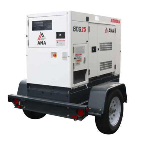
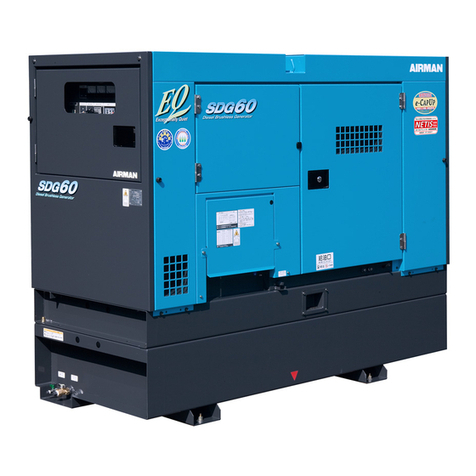
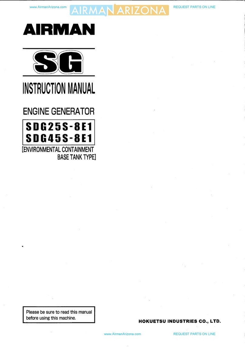
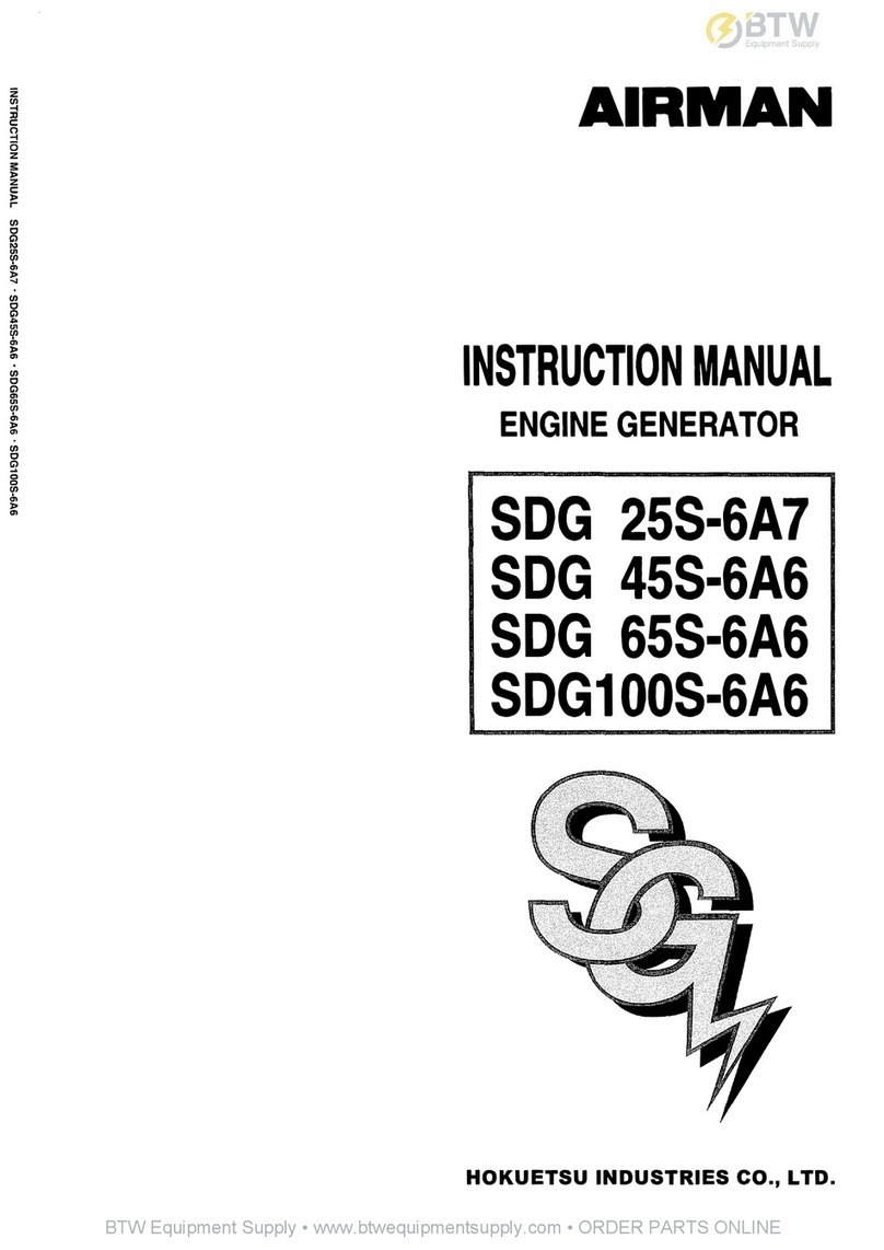
AirMan SDG25S-3A3 User manual

www.AirmanArizona.com
REQUEST PARTS ON LINE
www.AirmanArizona.com
REQUEST PARTS ON LINE

Preface
This operation manual explains and illustrates proper handling of the unit and the method of daily
inspection and maintenance which will enhance the performance of AIRMAN’s generators.
Before operating unit, read the manual carefully and fully understand its operation and maintenance
requirement. Then maintain “SAFETY OPERATION AND PROPER MAINTENANCE OF THE UNIT”.
Keep the manual available at all times for the operator or safety supervisor.
In case the manual is lost or damaged, place an order with your dealer for another copy.
Make sure that the manual is included with the unit when it is handed over to another user.
There may be minor inconsistency in detail between the manual and the actual machine due to
improvements of the machine. Ask your dealer if you have any questions or problems.
If you need parts or service information about the unit, please give your dealer model and serial
number of the unit. A plate stamped with model type and serial number is attached to the right hand
side of the instrument panel of the unit.
MODEL:
SER.NO.:
Be sure to follow safety warnings and cautions given in the manual. Unsafe operation could cause
serious injury or death.
A
010053
www.AirmanArizona.com
REQUEST PARTS ON LINE
www.AirmanArizona.com
REQUEST PARTS ON LINE

Table of Contents
TOC-1
1. Safety..................................................................................................................................................
1- 1
1. 1 Caution before Operation...........................................................................................................
1- 2
1. 2 Caution during Operation...........................................................................................................
1- 7
1. 3 Caution during Inspection and Maintenance..............................................................................
1-10
1. 4 Safety Warning Labels...............................................................................................................
1-13
2. Names of Components .....................................................................................................................
2- 1
2. 1 Unit Appearance and Part Names...........................................................................................
2- 1
2. 2
Main
Components and Part Names .........................................................................................
2- 2
2. 3 Instrument Panel........................................................................................................................
2- 4
2. 4 Warning and Emergency Display...............................................................................................
2- 5
2. 5 GFCI (GROUND-FAULT CIRCUIT INTERRUPTER) RECEPTACLES.....................................
2- 6
3. Transportation ...................................................................................................................................
3- 1
4. Installation..........................................................................................................................................
4- 1
4. 1 Place and Conditions of Unit Installation....................................................................................
4- 1
4. 2 Selecting Cable..........................................................................................................................
4- 2
4. 3 Connecting Load........................................................................................................................
4- 2
4. 4 Grounding Method .....................................................................................................................
4- 5
5. Operation............................................................................................................................................
5- 1
5. 1 Check before Starting the Unit...................................................................................................
5- 1
5. 2 Unit Operation............................................................................................................................
5- 6
5. 3 Stopping Procedures..................................................................................................................
5-10
5. 4 Operating Procedures when Engine Fails to Start up on First Attempt......................................
5-10
5. 5 Adjustment of frequency ............................................................................................................
5-11
5. 6 Emergency Stop.........................................................................................................................
5-12
5. 7 Air Bleeding................................................................................................................................
5-12
6. Periodic Inspection and Maintenance .............................................................................................
6- 1
6. 1 Important Items at Periodic Inspection and Maintenance or after Maintenance........................
6- 1
6. 2 Daily Inspection and Keeping Operation Log.............................................................................
6- 2
6. 3 Inspection and Location of Componets......................................................................................
6- 3
6. 4 First Maintenance at Initial 50 Hours..........................................................................................
6- 5
6. 5 Maintenance Every 250 Hours...................................................................................................
6- 7
6. 6 Maintenance Every 300 Hours...................................................................................................
6- 9
6. 7 Maintenance Every 500 Hours...................................................................................................
6-10
6. 8 Maintenance Every 600 Hours...................................................................................................
6-11
6. 9 Maintenance Every 1000 Hours.................................................................................................
6-12
6.10 Maintenance Every 2000 Hours.................................................................................................
6-14
6.11 Periodic Inspection List..............................................................................................................
6-15
7. Maintenance/Adjustment..................................................................................................................
7- 1
7. 1 Automatic Shut-Down System ...................................................................................................
7- 1
7. 2 Maintenance of Battery..............................................................................................................
7- 1
7. 3 Adjusting controller for automatic starting..................................................................................
7- 2
7. 4 Troubleshooting .........................................................................................................................
7- 3
8. Storage of the Unit............................................................................................................................
8- 1
8. 1 Preparation for Long-term Storage ............................................................................................
8- 1
9. Specifications ....................................................................................................................................
9- 1
10. Wiring Diagram..................................................................................................................................10- 1
10. 1 Generator Wiring Diagram.........................................................................................................10- 1
10. 2 Engine Wiring Diagram..............................................................................................................10- 5
www.AirmanArizona.com
REQUEST PARTS ON LINE
www.AirmanArizona.com
REQUEST PARTS ON LINE

1. Safety
1-1
This operation manual explains and illustrates general requirements for safety and cautions for
safety.
Read these safety requirements carefully and fully understand the contents before starting the
machine.
For better understanding, according to the degree of potential danger harmful to a human body,
safety messages are classified into three hierarchical categories, namely, , ,
and with a caution symbol −attached to each message.
When one of these messages is found, please take preventive measures for safety to carry out
“SAFETY OPERATION AND PROPER MAINTENANCE OF THE UNIT.”
DANGER indicates an imminently hazardous situation which, if not avoided,
will result in death or serious injury. This signal word is to be limited to the
most extreme situations.
WARNING indicates a potentially hazardous situation which, if not avoided,
could result in death or serious injury.
CAUTION indicates a potentially hazardous situation which, if not avoided,
may result in minor or moderate injury. It may also be used to alert against
unsafe practices.
IMPORTANT indicates important caution messages for the performance or
durability of the unit.
Follow warnings mentioned in this manual. This instruction manual does not describe all safety
items. We, therefore, advise you to pay special attention to all items (even though they may not
be described in the manual) for your safety.
www.AirmanArizona.com
REQUEST PARTS ON LINE
www.AirmanArizona.com
REQUEST PARTS ON LINE

1.Safety
1-2
1.1 Caution before Operation
Make sure not to connect the output terminal of the
machine with commercial power source from electric
power company. It may cause electric shock, machine
problems and even a fire.
Any source of high voltage is a source of potential
LETHAL voltage. Maintain all electrical cords and
connections in proper condition. Do not operate the unit
in the rain, around standing water or when wet. Always
ground the generator properly before operating.
Never allow untrained or unqualified individuals to
operate or remain in the vicinity of the equipment when
it is operating.
When connecting a cable to the load, do not use a
cable with damaged covering or with inappropriate
insulation.
Make sure connections between input/output
terminals are tight. Otherwise, it may loosen during
operation which may cause a fire or electric shock
accident.
Exhaust gas from the engine is poisonous, and could
cause death when inhaled.
Avoid using the machine in an insufficiently ventilated
building or tunnel.
SG0101
Ventilation
H990208
PC002
www.AirmanArizona.com
REQUEST PARTS ON LINE
www.AirmanArizona.com
REQUEST PARTS ON LINE

1.Safety
1-3
Keep flames away from battery.
Batteries generate hydrogen gas and may explode.
Therefore, recharging should be done in a well-ventilated
place.
Do not allow sparks, lighted match, or lit cigarette close to
the battery.
Do not check the battery by short-circuiting the positive and
negative terminals with a metallic object.
Do not charge the frozen battery. Otherwise it may explode.
If the battery is frozen, warm it up until the battery
temperature becomes 61°
Fto 86°
F (16℃to 30℃).
Battery electrolyte is diluted sulfuric acid.
In case of mishandling, it could cause skin burning.
Wear protective gloves and safety glasses when handling a
battery.
If battery electrolyte contacts your clothes or skin, rinse with
large amounts of water immediately.
If the battery electrolyte gets into your eyes, rinse
immediately with plenty of water and see a doctor at once,
because eyesight could be damaged.
Dispose of battery, observing local regulations.
Read each instruction plate which is displayed in the
manual and on the unit carefully, understand its content and
follow all rules and warnings.
Keep the Safety Warning labels clean. When they are
damaged or missing, apply to your dealer for new ones.
Do not modify the machine without prior approval. Safety of
the machine may be compromised, functions may be
deteriorated, or machine life may be shortened.
Never use the unit for purposes other than power supply.
Otherwise, serious accidents may occur.
Do not operate the machine if you are tired, impaired or under the influence of drugs. Otherwise,
careless handling may cause an unexpected injury or accident. Manage your physical and
mental health and be cautious in handling the machine.
Handling battery
Follow the safety instructions
Maintain both physical and mental health
D004
W010
TR0086
TR0093
www.AirmanArizona.com
REQUEST PARTS ON LINE
www.AirmanArizona.com
REQUEST PARTS ON LINE

1.Safety
1-4
Use the lifting bail (1) in the center of bonnet for hoisting up
and down the machine. Since the rope hook (2) in not strong
enough to be used for hoisting, never use it to prevent falling
accident.
When transporting the machine, be sure to put it on the truck
bed and use the rope hooks to secure it with rope(3) in the
center of bonnet. Apply chocks(4) to fix the machine on the
truck bed when necessary.
Select an appropriate crane and truck by referring to the mass
and dimensions shown in “Specifications” in Chapter 9.
Only the qualified crane operator is allowed to operate a crane.
Do not hoist up the machine while it is running. Otherwise, a
fatal trouble or serious accident may occur to the machine parts.
The machine must be installed on dry, firm and level area.
In case the machine has to be installed on a slope, keep
the inclination angle less than 5 degrees.
Avoid installing the machine in a place such as a damp
area or a place where puddles might form after rain. Such
an installation could cause electric shock.
Do not direct the exhaust gas outlet to nearby personnel or
houses in the vicinity.
When installing the machine at salt water areas or on a ship,
make sure the machine is not exposed directly to sea water.
When installing the machine at sandy areas, make sure that
exhaust from the generator or radiator does not blow the
sand in the air, or into the machine.
The machine should be operated in following conditions:
Ambient temperature 5°
Fto 104°
F
(–15℃to +40℃)
Humidity Less than 85%
Altitude Lower than 1,640ft (500 m) above sea level
Transportation
Installation
SG0103
3 4
2
1
SG0102
www.AirmanArizona.com
REQUEST PARTS ON LINE
www.AirmanArizona.com
REQUEST PARTS ON LINE

1.Safety
1-5
Such things as unnecessary equipment, tools, cables, hoods, covers and wood pieces which are
a hindrance to the job, must be cleared and removed. Operators and/or personnel nearby may
stumble on them and could be injured.
Be sure to check the unit before operation.
When any abnormality is found, be sure to repair it before restarting the unit.
Be sure to make daily checks before operation. If the unit is operated without prior checking and
a potential problem was not found, operation of the unit may cause seizure of components or
cause a fire.
When operating the machine, do not wear;
loose clothes
clothes with unbuttoned sleeves
hanging tie or scarf
loose fitting jewelry
Such outfit may get caught into the machine rotating parts
and this could cause a serious injury.
Wear helmet, safety glasses, earplugs, safety shoes, safety
gloves and a mask, according to the requirements of each
operation.
Have first-aid boxes and fire-extinguishers near the unit
ready for emergency situations such as injuries or fire.
It is advisable to have a list of phone numbers for doctors,
ambulance and the fire department available in case of
emergency.
Safety around the machine
Safety equipment
Safety aids
Check before starting the unit
Safety outfit
TR0084
TR0085
TR0096
www.AirmanArizona.com
REQUEST PARTS ON LINE
www.AirmanArizona.com
REQUEST PARTS ON LINE

1.Safety
1-6
When stacking up the machines for storage, only two
units stacking is acceptable.The mass of the lower
machine should be larger than that of the upper one.
Select a leveled floor with sufficient strength for stacking
up the units.
Before stacking the machines up, check the machine for
any deformation of bonnet, looseness or missing of bolts,
and other parts.
When stacking the units up, be sure to fix them as shown
in the figure so that the balanced weight is applied to
each squared lumber (1) for preventing a sideslip or a
collapse.
Never operate the machines with stacking conditions. It
is very dangerous.
It is dangerous to stack the machines, because they
could fall down due to sideslip or collapse when an
earthquake happens. Pay careful attention to the storage floor for safety.
Stacking up box type machines
1
SG0104
www.AirmanArizona.com
REQUEST PARTS ON LINE
www.AirmanArizona.com
REQUEST PARTS ON LINE

1.Safety
1-7
1.2 Caution during Operation
Never touch the output terminals during operation.
Pay attention that high voltage is present at the output
terminals.
When removing or connecting a "load" cable, be sure to
switch OFF the circuit breaker. Turn off the machine,
remove the starter key from the starter switch, then change
cables. The operator must hold the key during cable
changing.
Neglecting the cautions mentioned above, and a third party
starting the machine during operation may cause serious
accidents such as electric shock.
Never touch the interior of the control panel during
operation.
Pay attention that high voltage is present at interior of the
control panel.
Authorized personal only to open control panel.
Keep hands clear from the rotating portion or belts while
running. It could cause serious injuries if hands should be
caught.
Never put your hand near the engine cooling fan during
operation. It could cause serious injury if a hand should be
caught.
Never touch the interior of control panel
H990208
Hands off from rotating parts and belts
TR0304
Beware of cooling fan
W009
Keep away from output terminals
H990208
www.AirmanArizona.com
REQUEST PARTS ON LINE
www.AirmanArizona.com
REQUEST PARTS ON LINE

1.Safety
1-8
Do not, under any circumstance, open the radiator cap
while running or immediately after stopping operation.
Otherwise high temperature steam is released and this
could cause scalding.
Never work nearby hot portions of the machine while it is
running.
Do not touch hot portions of the machine while inspecting.
Such parts as engine, exhaust manifold, exhaust pipe,
muffler, and radiator are especially hot, stay clear of these
parts. It could cause serious burns.
Coolant water and engine oil are also very hot and
dangerous to touch. Avoid checking or refilling them while
the unit is running.
Do not, under any circumstance, bring lit cigarettes or
matches near diesel fuel oil, and engine oil, etc. They are
extremely flammable and dangerous, so be careful when
handling.
Refilling oils should be done in an outdoor well-ventilated
area.
Refuel after stopping the engine, and never leave the fuel
nearby the machine. Do not spill. It may cause a fire. If
spilled, clean up completely.
Muffler and exhaust pipe can be extremely hot. Remove
twigs, dried leaves, dried grass and waste paper, etc. from
the exhaust outlet of the muffler.
Keep a fire extinguisher available near the machine in case
of an unexpected fire.
Do not touch hot parts
Fire prevention
D004
Do not remove radiator cap during operation
H990432
H990433
www.AirmanArizona.com
REQUEST PARTS ON LINE
www.AirmanArizona.com
REQUEST PARTS ON LINE

1.Safety
1-9
Do not, under any circumstance, open these during
operation:
Coolant drain valve and plug
Engine oil drain plug
Reduce the load if the circuit breaker actuates frequently during operation.
When a single-load is used, check the current of each phase, and adjust the load so that each
load value remains balanced.
If the above procedure is neglected during operation, the generator could be damaged or cause
a fire. If the machine is operated with the frequency lower than the rated frequency, it could
cause the generator or load to be damaged.
Unbalance of overload and load
PK0028
Draining during operation prohibited
www.AirmanArizona.com
REQUEST PARTS ON LINE
www.AirmanArizona.com
REQUEST PARTS ON LINE

1.Safety
1-10
1.3 Caution during Inspection and Maintenance
Before starting inspection, switch off the circuit breaker of
the machine, remove the key from the starter key switch,
hang a “Now Checking and under Maintenance” tag where
it can be easily seen. Operator and service personnel must
keep the key during checking and maintenance.
Remove the negative (–) side cable from the battery.
If the above procedure is neglected, and another person
starts operating the machine during check or maintenance,
it could cause serious injury.
Be sure to stop the engine and remove the starter key
whenever fan belt tension is to be adjusted.
If the machine is running, it might catch the operator’s hand
into the fan belts, and this could cause a serious injury.
Be sure to stop the engine and remove the starter key
whenever check or maintenance work is carried out near
the cooling fan.
If the cooling fan is rotating, it may catch the operator or
part of his body into the fan, which could cause a serious
injury.
When cleaning dust accumulated in components such as
radiator, air-filter, etc., when blowing compressed air, wear
safety glasses, etc. to protect your eyes.
Cleaning with compressed air
Hang a “Now Checking and under Maintenance” tag
SY001
A
djusting tension of fan belt
Hands off from cooling fan
W009
TR0304
M003
www.AirmanArizona.com
REQUEST PARTS ON LINE
www.AirmanArizona.com
REQUEST PARTS ON LINE

1.Safety
1-11
Do not attempt operating or servicing the machine in the dark.
It is recommended to use a lamp which has a safety guard.
Operating or servicing the machine in the dark may cause
unexpected accidents.
Lamps without safety guards are not recommended since
they are easily broken and could ignite flammables such as
fuel, etc.
Before removing radiator cap, let machine cool down to a
safe temperature and loosen the radiator cap one notch
which will release any remaining inner pressure. The coolant
must be sufficiently cooled to a safe level and the inner
pressure completely released. Then take the cap off.
If this procedure is not followed, the inner pressure can blow
off the cap when turned. Steam jetting out of the radiator
could result in scalding. Follow these procedures under all
circumstances.
Be sure to stop the engine, and let the coolant water
sufficiently cool down before draining it.
If the drain valve is opened before the coolant water is cooled
enough, hot water jetting out of the drain valve could result in
scalding.
Lighting apparatus
TR0206
Removing radiator cap
Opening coolant water drain valve
H990432
H990432
www.AirmanArizona.com
REQUEST PARTS ON LINE
www.AirmanArizona.com
REQUEST PARTS ON LINE

1.Safety
1-12
After stopping the engine, wait until engine cools down. Then
check the level of the engine oil, refill or drain the oil.
Engine oil is very hot and highly pressurized during or just
after engine operation, while draining oil, make sure engine is
cool. Hot oil could result in scalding.
When washing the machine, cover the control panel, generator and its electric parts to prevent
them from being exposed to splashing water. This will avoid decrease in electrical insulation or
other problems to the machine.
Waste liquid from the machine contains harmful material. Do not discharge onto the ground, river,
lake or sea. Such material will contaminate the environment.
Use a container to hold the waste liquid taken from the machine.
Follow designated regulations when disposing of oil, fuel, coolant (antifreeze), battery or other
harmful materials.
Refilling or draining of engine oil
Cleaning the unit
Disposal of waste liquid, etc.
H990432
www.AirmanArizona.com
REQUEST PARTS ON LINE
www.AirmanArizona.com
REQUEST PARTS ON LINE

1.Safety
1-13
1.4 Safety Warning Labels
SDG25S
Following labels are attached to the machine.
Keep them clean all the times. If they are damaged or peeled off, immediately place an order with
your nearest dealer for replacement., with the numbers indicated on the lower right corner of the
label. Adhere a new one to the original place.
1. Lifting bail
(39176 69300)
2. Caution Do not touch
(39176 62900)
3. Caution exhaust gases
(39176 73300)
4. Caution, before starting
(39176 35701)
5. Caution, cooling fan
(39176 73500)
6. Caution, fan belt
(39176 73800)
7. Caution, high temp
(39176 69500)
8. Caution, open panel
(39176 65501)
9. Caution,radiator
cap(hot water)
(39176 69600)
10. NO Fire
(39176 35600)
11. Caution, high voltage
(39176 62400)
12. Caution battery
(39176 50000)
13. Caution, Do not switch
(39176 62700)
7
6
11
12
2
13
1
9
5
8
2
4 3
10
P010037
www.AirmanArizona.com
REQUEST PARTS ON LINE
www.AirmanArizona.com
REQUEST PARTS ON LINE

1.Safety
1-14
SDG45S/60S
Following labels are attached to the machine.
Keep them clean all the times. If they are damaged or peeled off, immediately place an order with
your nearest dealer for replacement., with the numbers indicated on the lower right corner of the
label. Adhere a new one to the original place.
1. Lifting bail
(39176 69300)
2. Caution Do not touch
(39176 62900)
3. Caution exhaust gases
(39176 73300)
4. Caution, before starting
(39176 35701)
5. Caution, cooling fan
(39176 73500)
6. Caution, fan belt
(39176 73800)
7. Caution, high temp
(39176 69500)
8. Caution, open panel
(39176 65501)
9. Caution,radiator
cap(hot water)
(39176 69600)
10. NO Fire
(39176 35600)
11. Caution, high voltage
(39176 62400)
12. Caution battery
(39176 50000)
13. Caution, Do not switch
(39176 62700)
7
6
11 12
2
13
1
9
5
8
2
10
4
3
P010038
www.AirmanArizona.com
REQUEST PARTS ON LINE
www.AirmanArizona.com
REQUEST PARTS ON LINE

1.Safety
1-15
SDG75S/100S
Following labels are attached to the machine.
Keep them clean all the times. If they are damaged or peeled off, immediately place an order with
your nearest dealer for replacement., with the numbers indicated on the lower right corner of the
label. Adhere a new one to the original place.
1. Lifting bail
(39176 69300)
2. Caution Do not touch
(39176 62900)
3. Caution exhaust gases
(39176 73300)
4. Caution, before starting
(39176 35701)
5. Caution, cooling fan
(39176 73500)
6. Caution, fan belt
(39176 73800)
7. Caution, high temp
(39176 69500)
8. Caution, open panel
(39176 65501)
9. Caution,radiator
cap(hot water)
(39176 69600)
10. NO Fire
(39176 35600)
11. Caution, high voltage
(39176 62400)
12. Caution battery
(39176 50000)
13. Caution, Do not switch
(39176 62700)
7
6
11
12
2
13
9
5
8
10
4
3
1
P010039
2
www.AirmanArizona.com
REQUEST PARTS ON LINE
www.AirmanArizona.com
REQUEST PARTS ON LINE

2. Names of Components
2-1
2.1 Unit Appearance and Part Names
SDG25S
www.AirmanArizona.com
REQUEST PARTS ON LINE
www.AirmanArizona.com
REQUEST PARTS ON LINE

2. Names of Components
2-2
2.2 Main Components and Part Names
SDG25S
SDG45S/60S
①Control panel
②Voltage selector switch
③ Battery
④Engine oil dipstick
⑤Air filter
⑥Engine
⑦Reserve tank
⑧Generator
⑨Fuel air-bleeding electromagnetic pump
⑩Engine oil filter
⑪Fuel filter
⑫Sedimenter
⑬Engine oil filler
⑭Radiator
⑮Fuel tank
H990173
H990172
www.AirmanArizona.com
REQUEST PARTS ON LINE
www.AirmanArizona.com
REQUEST PARTS ON LINE
This manual suits for next models
4
Table of contents
Other AirMan Inverter manuals
Popular Inverter manuals by other brands

Sungrow
Sungrow SG8KTL-EC Quick user manual

Technaxx
Technaxx TX-200 user manual

Inovonics
Inovonics 708 Operating and maintenance instruction manual

INVT
INVT CHV100 Series Operation manual

Atlas Copco
Atlas Copco QAS 250-330 JD T4i instruction manual

South-Tek Systems
South-Tek Systems N2Blast FPS-650 manual