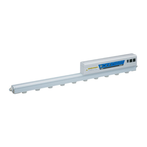
AirPlus DMR-6000 User manual

DMR-6000
©2023 Air+ Rev2 9/23
INSTALLATION, OPERATION,
AND MAINTENANCE MANUAL

GENERAL DESCRIPTION
The Air+ DMR-6000 is an auto-cleaning, zero-ozone, needlepoint ionizer producing billions of positive
and negative ions that deactivate bacteria and viruses, agglomerate particulate, and neutralize other
harmful pollutants. No maintenance is required as the needles are cleaned of dirt and dust automati-
cally and programmed from the factory at once per 24 hours of operation and upon start-up. The
DMR-6000 can be installed in the supply duct of any air handling system. The goal of the technology
is to introduce ions to the airflow and have them delivered to the occupied space, so mount the
DMR-6000 as close to the supply diffusers as possible. .
The unit can be powered with 12V or 24V, AC or DC, or a power supply can be provided for utilizing
120V or 240V AC power. The unit has communication capabilities including a dry contact and data
export to the BMS. The DMR-6000 provides an electronic signal only when the ionizer is creating ions.
This signal is used to initiate a relay that closes the dry contact and powers the Ionization LED. The
DMR-6000 is UL2998 validated for zero ozone emissions. ..
MECHANICAL INSTALLATION
The preferred location of the DMR-6000 is in the supply air duct leaving the air handler. Be
sure to pick a location before any branch duct take-offs and ensure access to all switches and
power/communication input and data output terminals. To improve the effectiveness of the
filter, the DMR-6000 can be installed in the return duct upstream of the filter. .
1.
To mount the unit in a round duct system (See Figures 1 and 2): .2.
Install the DMR-6000 such that the ionizing needles are pointed downstream of the airflow.
A directional arrow is located on the label to aid in unit orientation. (See Figure 2). .
.
3.
Confirm that the round duct diameter is the same as the diameter of the
DMR-6000. Slide the female round duct over the male slip fitting. (See Figure 1). .
a.
Screw through the duct and fitting joint using sheet metal screws (not provided)
and seal the duct joint as necessary. (See Figure 2). .
b.
CAUTION: The DMR-6000 should not be installed immediately downstream of a humidifier
or exposed to any moisture. .
CAUTION: This product is intended for mounting into metallic construction only. .
FIGURE 1
FEMALE
DUCT
12V-24V AC OR DC
POWER INPUT
MALE
FITTING

ELECTRICAL INSTALLATION
Ideally, a dedicated 24V AC transformer be used to power the DMR-6000. If this is not pos-
sible, power from a transformer serving other equipment may be used if sized adequately
to handle the additional VA rating of the DMR-6000. The power source should be protect-
ed by a circuit breaker not exceeding 20 Amps. . .
1.
Power can be connected by either bringing 24V AC or DC directly to the terminal block on
the unit or using a factory provided 120V/240V to 12V DC power supply (Air+ Part No.
PS-Low). Connect 2.1mm pin to pin jack on the unit. (See Figure 3). ..
2.
To communicate with the BMS, connect BMS wires to the terminal block on the outside
of the unit. (See Figure 3). .
3.
Once power is connected to the unit, press the power switch to the "ON" position. The LED
should illuminate. (See Figure 4). .
.
4.
CAUTION: Do not connect power to the DMR-6000 before the installation is complete.
Always disconnect power before handling any of the unit components. .
CAUTION: Surge protection should be utilized for this product at the equipment or
circuit feeding the ionizer. A transformer used to power the product must be grounded.
FIGURE 3
24V AC or DC
OPTION 1
POWER
SUPPLY
120V/240V AC12V DC
OPTION 2 DMR-6000
Control Panel
BMS WIRING TO ALARM CONTACTS (OPTIONAL)
Air+ Part No. PS-Low
Wiring and equipment provided by Air+
Wiring provided by contractor
*
*
FIGURE 2
SEAL DUCT
JOINT AS
REQUIRED
AIRFLOW AIRFLOW
SELF TAPPING
SHEETMETAL SCREWS

Air+, Inc | 222 Purchase St, Suite 210, Rye, NY 10580
Ph: 203-883-6700 | Fax: 203-883-6724 | info@air-plus.com | air-plus.com
OPERATION
The DMR-6000 has an Alarm Circuit that provides for communication to the BMS. The Alarm
Circuit utilizes a relay with normally closed contacts. The contacts are open whenever the unit is
not powered or there is a fault in the system. When the DMR-6000 is operating normally and pro-
ducing ions, the contacts close and the LED on the outside of the unit will illuminate. Connect
the BMS control wires to the BMS terminal block on the outside of the unit. (See Figure 3).
.
TROUBLESHOOTING
BMS ALARM CONTACTS
ON
OFF
When the power switch is turned to the “On” position, the DMR-6000 will activate, the LED will
illuminate, and the unit will produce ions. After about a minute, the self-cleaning mechanism
will run through its complete cleaning cycle and the unit will produce ions again. .
1.
If the DMR-6000 is not operating, check that the power switch is set to the “On” position and
the Ionization LED is illuminated. .
1.
The DMR-6000 has an internal automatically resetting fuse. If the fuse trips, remove power by
turning the power switch off, wait 2-5 minutes for the fuse to reset and turn power back on. If
the fuse trips again, contact customer support. .
3.
Confirm that all power wiring is connected properly to the terminal block on the outside of
the unit. Test the BMS Dry Contacts using a multimeter set to continuity mode. If the multime-
ter alarms, the circuit is continuous, and operation is confirmed. If it does not alarm, the circuit
is not continuous and there is a problem. Contact Air+ customer support as needed. ..
2.
Because the DMR-6000 is self-cleaning, no maintenance of any kind is required. The cleaning
cycle is factory programmed to initiate every 24 hours and upon start-up. .
2.
FIGURE 4
ON/OFF
SWITCH IONIZATION
LED
VALIDATED
ZERO OZONE EMISSIONS -
MEASURED OZONE
EMISSIONS FROM AIR+
DM-6000 DURING USE
PHASE DOES NOT EXCEED
0.005 PPM AS TESTED BY
UL 867
UL.COM/ECV
E534812
Once power is connected to the unit, press the power switch to the "ON" position. The LED
should illuminate. (See Figure 4). .
.
CAUTION: Do not connect power to the DMR-6000 before the installation is complete.
Always disconnect power before handling any of the unit components. .
CAUTION: Surge protection should be utilized for this product at the equipment or
circuit feeding the ionizer. A transformer used to power the product must be grounded.
Table of contents
Other AirPlus Air Ionizer manuals
Popular Air Ionizer manuals by other brands

ESD SYSTEMS
ESD SYSTEMS Auto-Ion Operation installation and maintenance

ITW
ITW Simco ION Installation and operating instructions

Steren
Steren AIR-300 user manual

UNITED
UNITED ElectraFlow HDG-600 Specifications and installation

Desco EMIT
Desco EMIT 50680 Technical bulletin

AtmosAir
AtmosAir Matterhorn 1000 Series Installation, operation and maintenance guide