M5 ×6 mm
M5 ×6 mm
9k 10k
1
23
ESPAÑOL
ACCESORIOS DE MONTAJE SUMINISTRADOS
PARA LA INSTALACION
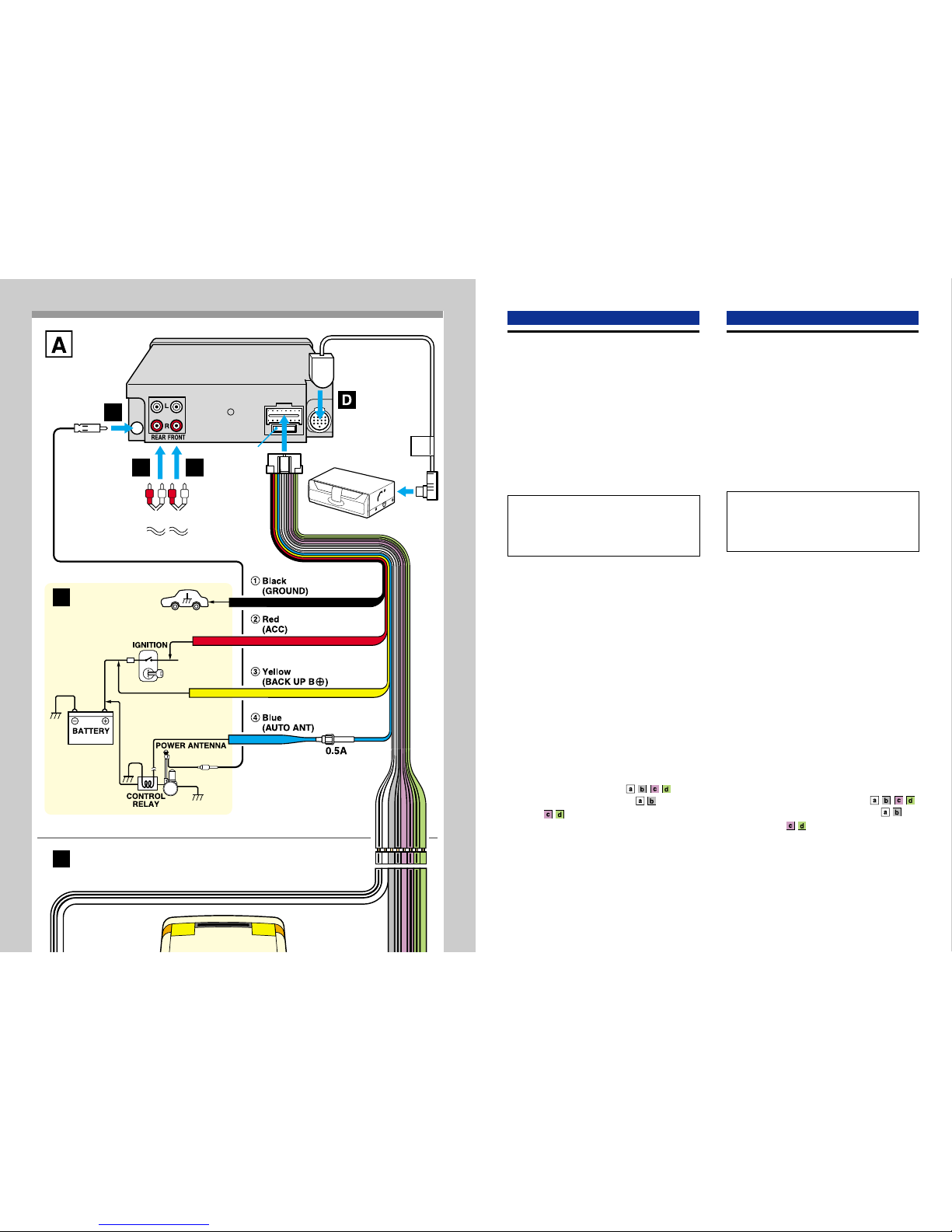
→A
INSTALACION
Lainstalacióndescritaalolargodeestemanualpresupone
que tiene un coche normal. Si su coche requiere ajustes
omodificaciones, consultecon suconcesionariodeaudio
para coches de AIWA más cercano.
PRECAUCIONES
• Este aparato fue diseñado para una conexión a tierra
negativa y funciona con una CC de 12 V.
• Antes de empezar la instalación, compruebe que el
interruptor de encendido está en OFF y desconecte el
terminal a tierra de la batería de coche para evitar que
se produzca un cortocircuito.
• Instale el aparato donde no moleste el funcionamiento
del vehículo.
• Instale el aparato en un lugar donde no provoque
heridasa lospasajeros porunfrenadorepentino,como
en el caso de un frenado de emergencia.
• Evite instalar el aparato donde quede expuesto a altas
temperaturasprovocadaspor losrayosdirectos delsol
oelaire caliente delacalefaccióno donde puedaestar
expuesto al polvo, suciedad o vibraciones excesivas.
• Utilice sólo los accesorios de montaje suministrados,
para una instalación firme y segura.
INSTALACION PREVIA →B
Siyasehaninstaladoaccesoriosparainstalacióndeotro
aparato en el tablero, deberá desmontarlos.
Desmonte la placa de adorno del aparato →1
Desmonte la placa de adorno aempujando las partes
superior e inferior de la placa en el sentido de la flecha.
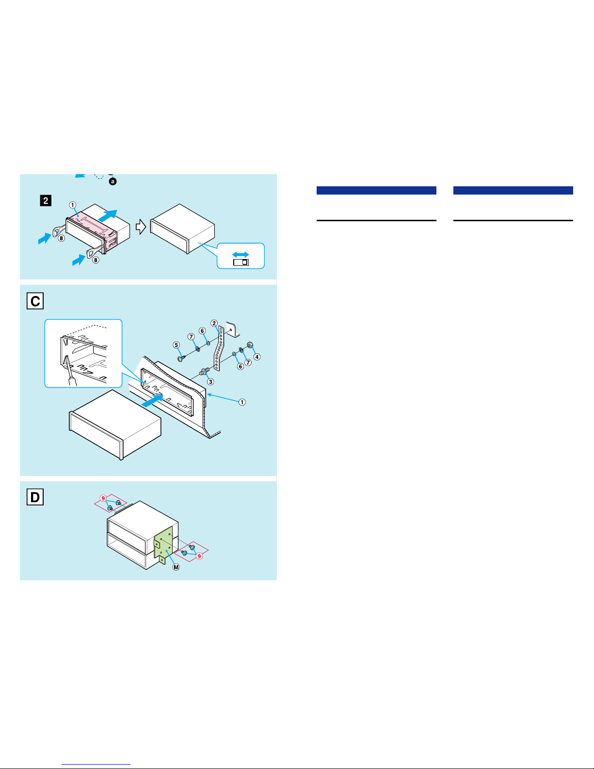
Desmonte el manguito de instalación →2
Insertelaspalancas
8
alolargo de cada ranura enambos
ladosdelaparato paradestrabar elmanguitode instalación
1
y tire del manguito para desmontarlo de la del aparato.
Interruptorde 9k/10k(enlaparteinferior delaparato)
Consulte la sección “ESPECIFICACIONES” del manual
de instrucciones que se entrega por separado (ajuste a
10k en la fábrica).
INSTALACION BASICA →C
Instalación en el tablero
Tenga en cuenta que la instalación que se describe es a
mododeejemplo.Paraalgunosmodelosdecoche,puede
sernecesariohacerajustesomodificacionesparainstalar
el aparato. Si su coche es de este tipo, consulte con su
concesionariodeaudioparacochesdeAIWAmáscercano.
Ajuste del ángulo de montaje
Elángulode montaje debeserde 30gradosomenos de
la horizontal.
Precauciones sobre la instalación sin
utilizar el manguito →D
Se deben utilizar siempre los tornillos
suministrados9queaparecenenA,parainstalar
las ménsulas de montaje M(no suministradas).
PORTUGUÊS
COMPONENTES DE MONTAGEM FORNECIDOS
PARA INSTALAÇÃO
→A
INSTALAÇÃO
Ainstalaçãodaformacomoédescritanestemanualaplica-
se aos veículos mais comuns. Se seu veículo exigir
particularmentequaisquerajustesoumodificações,consulte
o revendedor de som automotivo AIWA de sua região.
PRECAUÇÕES
• Esteaparelho foiprojetado parafuncionar somenteem
corrente contínua de 12 volts com terra negativo.
•
Antes da instalação, certifique-se de que a chave de
igniçãodoveículoestejadesligadaedesconecteoborne
de terra da bateria do veículo para evitar curto-circuito.
• Instale a unidade em lugar onde ela não venha a
prejudicar a condução do veículo.
• Instale o aparelho em lugar onde o mesmo não venha
a representar risco de ferimento dos passageiros em
caso de parada repentina, como por exemplo numa
freada de emergência.
•
Evite instalar o aparelho em lugar onde o mesmo fique
exposto a luz solar direta ou a ar quente gerado por
aquecedor. Evite também locais onde o aparelho fique
exposto a poeira, sujeira ou vibração excessiva.
• Utilize somente os componentes de montagem
fornecidos para assegurar uma instalação segura e
confiável.
PRÉ-INSTALAÇÃO →B
Sejáhouverferragemde instalação para outro receptor
no painel de instrumentos, ela deverá ser removida.
Remoção da moldura da unidade →1
Removaamoldura a, pressionando as partes superior
e inferior da moldura na direção da seta.
Remoção da luva de instalação →2
Introduza as alavancas
8
ao longo de cada ranhura nos
doisladosdaunidadeparadestravaraluvadeinstalação
1
e puxe a luva para separá-la da unidade.
Chave 9k/10k (localizada na base da unidade)
Veja a seção “ESPECIFICAÇÕES” nas instruções de
uso independentes (ajustada a 10k na fábrica).
INSTALAÇÃO BÁSICA →C
Instalação no painel de instrumentos
Note que a instalação aqui mostrada é a mais comum.
Para alguns tipos de veículos, talvez seja necessário
fazerajustesoumodificações para instalaraunidade. Se
seucarrofordeumdestestipos,consulteorevendedorde
som automotivo AIWA de sua região.
Ajuste do ângulo de montagem
O ângulo de montagem deve ser de 30 graus ou menos
em relação à base horizontal.
Precaução sobre a instalação sem o uso
da luva →D
Certifique-se de usar os parafusos fornecidos 9
que aparecem em Apara fixar os suportes de
montagem M(não fornecidos).