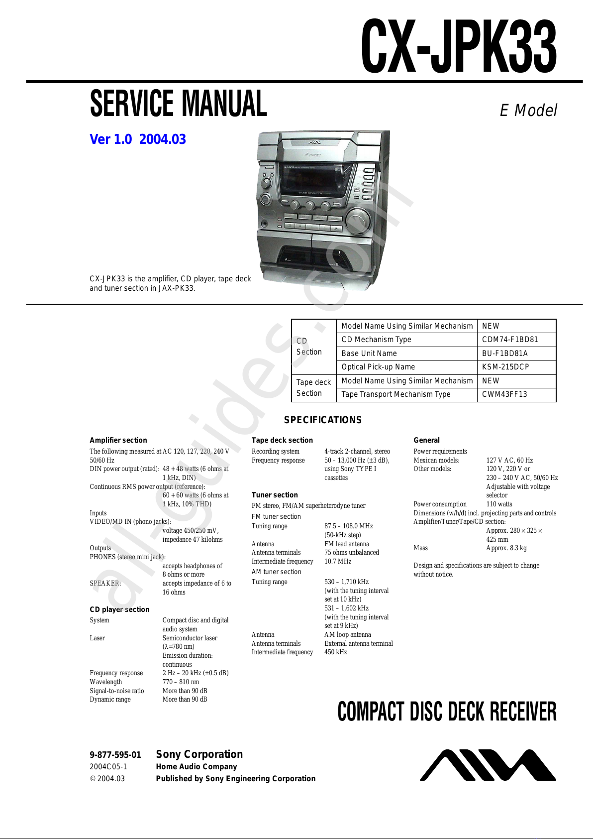
Aiwa CX-JPK33 User manual

SERVICE MANUAL
Outputs
PHONES (stereo mini jack):
accepts headphones of
8ohms or more
SPEAKER: accepts impedance of 6 to
16 ohms
CD player section
System Compact disc and digital
audio system
Laser Semiconductor laser
(λ=780 nm)
Emission duration:
continuous
Frequency response 2 Hz – 20 kHz (±0.5 dB)
Wavelength 770 – 810 nm
Signal-to-noise ratio More than 90 dB
Dynamic range More than 90 dB
Tape deck section
Recording system 4-track 2-channel, stereo
Frequency response 50 – 13,000 Hz (±3 dB),
using Sony TYPE I
cassettes
Tuner section
FM stereo, FM/AM superheterodyne tuner
FM tuner section
Tuning range 87.5 – 108.0 MHz
(50-kHz step)
Antenna FM lead antenna
Antenna terminals 75 ohms unbalanced
Intermediate frequency 10.7 MHz
AM tuner section
Tuning range 530 – 1,710 kHz
(with the tuning interval
set at 10 kHz)
531 – 1,602 kHz
(with the tuning interval
set at 9 kHz)
Antenna AM loop antenna
Antenna terminals External antenna terminal
Intermediate frequency 450 kHz
General
Power requirements
Mexican models: 127 V AC, 60 Hz
Other models: 120 V, 220 V or
230 – 240 V AC, 50/60 Hz
Adjustable with voltage
selector
Power consumption 110 watts
Dimensions (w/h/d) incl. projecting parts and controls
Amplifier/Tuner/Tape/CD section:
Approx. 280 ×325 ×
425 mm
Mass Approx. 8.3 kg
Design and specifications are subject to change
without notice.
The following measured at AC 120, 127, 220, 240 V
50/60 Hz
DIN power output (rated): 48 + 48 watts (6 ohms at
1kHz, DIN)
Continuous RMS power output (reference):
60 + 60 watts (6 ohms at
1kHz, 10% THD)
Inputs
VIDEO/MD IN (phono jacks):
voltage 450/250 mV,
impedance 47 kilohms
Amplifier section
COMPACT DISC DECK RECEIVER
E Model
CX-JPK33
Ver 1.0 2004.03
9-877-595-01 Sony Corporation
2004C05-1 Home Audio Company
© 2004.03 Published by Sony Engineering Corporation
SPECIFICATIONS
CX-JPK33 is the amplifier, CD player, tape deck
and tuner section in JAX-PK33.
Model Name Using Similar Mechanism NEW
CD CD Mechanism Type CDM74-F1BD81
Section Base Unit Name BU-F1BD81A
Optical Pick-up Name KSM-215DCP
Tape deck Model Name Using Similar Mechanism NEW
Section Tape Transport Mechanism Type CWM43FF13
All manuals and user guides at all-guides.com
all-guides.com

CX-JPK33
2
Notes on chip component replacement
•Never reuse a disconnected chip component.
•Notice that the minus side of a tantalum capacitor may be dam-
aged by heat.
Flexible Circuit Board Repairing
•Keep the temperature of the soldering iron around 270 °C dur-
ing repairing.
•Do not touch the soldering iron on the same conductor of the
circuit board (within 3 times).
•Be careful not to apply force on the conductor when soldering
or unsoldering.
CAUTION
Use of controls or adjustments or performance of procedures
other than those specified herein may result in hazardous ra-
diation exposure.
SAFETY-RELATED COMPONENT WARNING!!
COMPONENTS IDENTIFIED BY MARK 0OR DOTTED
LINE WITH MARK 0ON THE SCHEMATIC DIAGRAMS
AND IN THE PARTS LIST ARE CRITICAL TO SAFE
OPERATION. REPLACE THESE COMPONENTS WITH
SONY PARTS WHOSE PART NUMBERS APPEAR AS
SHOWN IN THIS MANUAL OR IN SUPPLEMENTS PUB-
LISHED BY SONY.
This appliance is classified as
a CLASS 1 LASER product.
The CLASS 1 LASER
PRODUCT MARKING is
located on the rear exterior.
UNLEADED SOLDER
Boards requiring use of unleaded solder are printed with the lead-
free mark (LF) indicating the solder contains no lead.
(Caution: Some printed circuit boards may not come printed with
the lead free mark due to their particular size)
: LEAD FREE MARK
Unleaded solder has the following characteristics.
•Unleaded solder melts at a temperature about 40 °C higher than
ordinary solder.
Ordinary soldering irons can be used but the iron tip has to be
applied to the solder joint for a slightly longer time.
Soldering irons using a temperature regulator should be set to
about 350 °C.
Caution: The printed pattern (copper foil) may peel away if the
heated tip is applied for too long, so be careful!
•Strong viscosity
Unleaded solder is more viscou-s (sticky, less prone to flow)
than ordinary solder so use caution not to let solder bridges oc-
cur such as on IC pins, etc.
•Usable with ordinary solder
It is best to use only unleaded solder but unleaded solder may
also be added to ordinary solder.
All manuals and user guides at all-guides.com

CX-JPK33
3
TABLE OF CONTENTS
1. SERVICING NOTES ................................................ 4
2. GENERAL
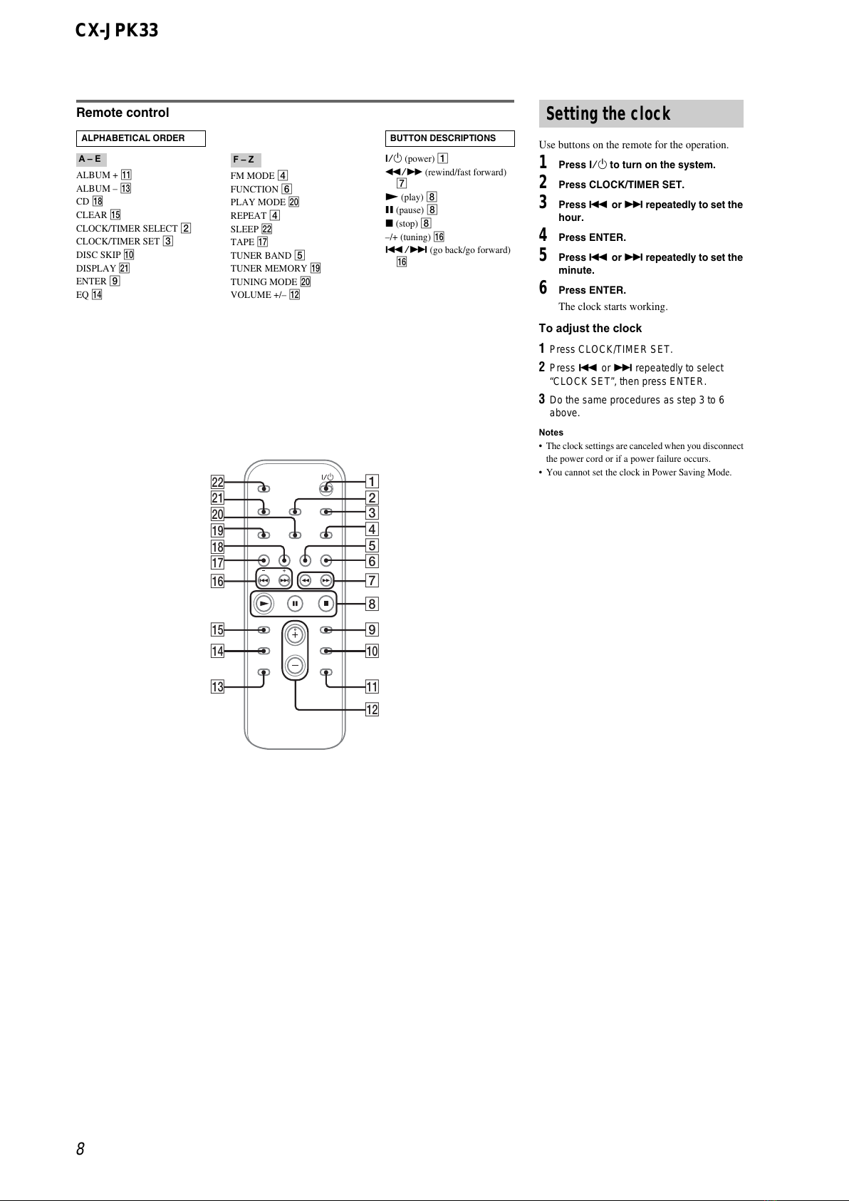
Location of Controls ....................................................... 7
3. DISASSEMBLY
3-1. Disassembly Flow ........................................................... 9
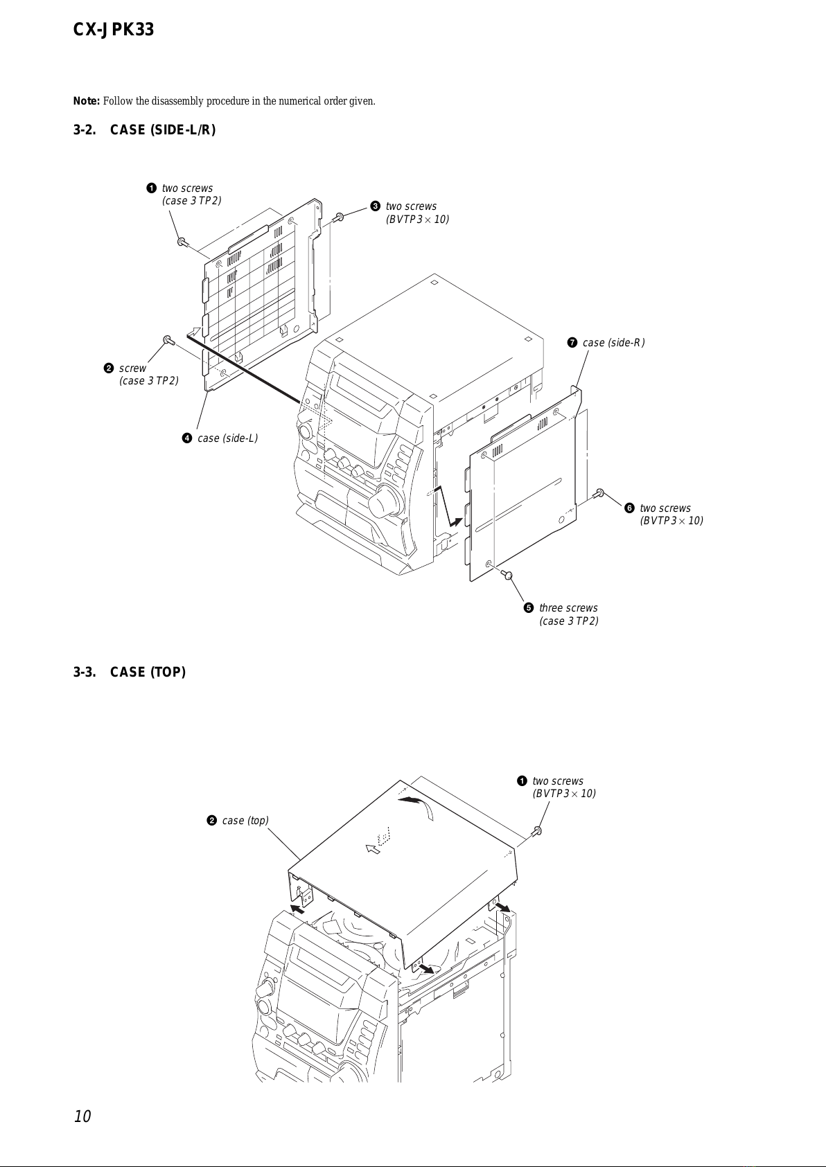
3-2. Case (Side-L/R)............................................................... 10
3-3. Case (Top) ....................................................................... 10
3-4. Tray Panel........................................................................ 11
3-5. CD Mechanism Deck (CDM74-F1BD81)...................... 11
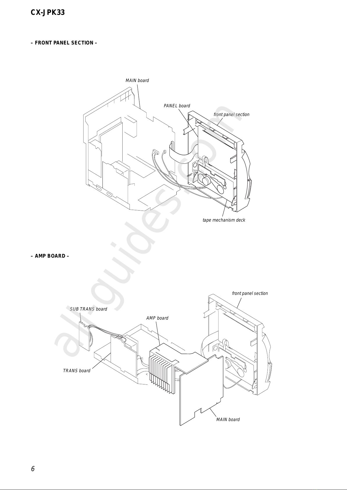
3-6. Front Panel Block............................................................ 12
3-7. Back Panel Section.......................................................... 12
3-8. MAIN Board ................................................................... 13
3-9. Tape Mechanism Deck (CWM43FF13) ......................... 13
3-10. Table Assy ....................................................................... 14
3-11. MOTOR (TB) Board ....................................................... 14
3-12. MOTOR (LD) Board....................................................... 15
3-13. Base Unit (BU-F1BD81A) ............................................. 15
3-14. Motor Gear Assy (Sled) (M102), CD Board .................. 16
3-15. Optical Pick-up (KSM-215DCP).................................... 16
4. TEST MODE.............................................................. 17
5. ELECTRICAL ADJUSTMENTS
CD Section ...................................................................... 21
6. DIAGRAMS
6-1. Block Diagram – SERVO Section – .............................. 22
6-2. Block Diagram – MAIN Section – ................................ 23
6-3. Block Diagram
– PANEL/POWER SUPPLY Section – .......................... 24
6-4. Note for Printed Wiring Boards and
Schematic Diagrams ....................................................... 25
6-5. Printed Wiring Board – CD Board – ............................. 26
6-6. Schematic Diagram – CD Board – ................................ 27
6-7. Printed Wiring Boards – CHANGER Section –............ 28
6-8. Schematic Diagram – CHANGER Section – ................ 29
6-9. Printed Wiring Board
– CDMP3 CONNECT Board – ...................................... 30
6-10. Schematic Diagram
– CDMP3 CONNECT Board – ...................................... 31
6-11. Schematic Diagram – MAIN Section (1/4) –................ 32
6-12. Schematic Diagram – MAIN Section (2/4) –................ 33
6-13. Schematic Diagram – MAIN Section (3/4) –................ 34
6-14. Schematic Diagram – MAIN Section (4/4) –................ 35
6-15. Printed Wiring Boards – MAIN Section – .................... 36
6-16. Printed Wiring Board – PANEL Section – .................... 37
6-17. Schematic Diagram – PANEL Section (1/2) – .............. 38
6-18. Schematic Diagram – PANEL Section (2/2) – .............. 39
6-19. Printed Wiring Board – POWER AMP Section – ......... 40
6-20. Schematic Diagram – POWER AMP Section – ............ 41
6-21. Printed Wiring Boards – TRANS Section – .................. 42
6-22. Schematic Diagram – TRANS Section – ...................... 43
7. EXPLODED VIEWS
7-1. Case Section .................................................................... 54
7-2. Tape Mechanism Deck Section (CWM43FF13) ............ 55
7-3. PANEL Board Section .................................................... 56
7-4. Cassette Box Section ...................................................... 57
7-5. Front Panel Section ......................................................... 58
7-6. Back Panel Section.......................................................... 59
7-7. Chassis Section ............................................................... 60
7-8. CD Mechanism Deck Section-1 (CDM74-F1BD81) ..... 61
7-9. CD Mechanism Deck Section-2 (CDM74-F1BD81) ..... 62
7-10. CD Mechanism Deck Section-3 (CDM74-F1BD81) ..... 63
7-11. Base Unit Section (BU-F1BD81A) ................................ 64
8. ELECTRICAL PARTS LIST ............................... 65
All manuals and user guides at all-guides.com

4
CX-JPK33
+
–
+
RLRL
–
– RearView –
PART No.
SECTION 1
SERVICING NOTES
NOTES ON HANDLING THE OPTICAL PICK-UP
BLOCK OR BASE UNIT
The laser diode in the optical pick-up block may suffer electro-
static break-down because of the potential difference generated
by the charged electrostatic load, etc. on clothing and the human
body.
During repair, pay attention to electrostatic break-down and also
use the procedure in the printed matter which is included in the
repair parts.
The flexible board is easily damaged and should be handled with
care.
NOTES ON LASER DIODE EMISSION CHECK
The laser beam on this model is concentrated so as to be focused
on the disc reflective surface by the objective lens in the optical
pick-up block. Therefore, when checking the laser diode emis-
sion, observe from more than 30 cm away from the objective lens.
LASER DIODE AND FOCUS SEARCH OPERATION
CHECK
Carry out the “S curve check” in “CD section adjustment” and
check that the S curve waveforms is output three times.
•MODEL IDENTIFICATION
MODEL PART No.
Mexican model 4-252-231-2[]
Chilean and Peruvian models 4-252-231-3[]
All manuals and user guides at all-guides.com

5
CX-JPK33
CD mechanism deck
stand
CDMP3 CONNECT board
SERVICE POSITION
– CD MECHANISM DECK –
HOW TO OPEN THE DISC TRAY WHEN POWER SWITCH TURNS OFF.
1
Remove the case (side-L).
2
Turn the loading gear in the direction
of arrow
A
.
A
3
Pull-out the disc tray.
All manuals and user guides at all-guides.com

6
CX-JPK33
– AMP BOARD –
– FRONT PANEL SECTION –
MAIN board
PANEL board
front panel section
tape mechanism deck
SUB TRANS board
TRANS board
AMP board
MAIN board
front panel section
All manuals and user guides at all-guides.com
all-guides.com

7
CX-JPK33
Main unit
ALBUM + wl
ALBUM – wl
BASS control 5
CD qh
CD SYNC qs
Deck A 9
Deck B wk
DISC 1 – 3 wd
DISC SKIP/EX-CHANGE wf
Disc tray ws
DISPLAY qg
Display window 4
ENTER 2
i-Bass qd
MIDDLE control 5
Operation Dial
(AMS/TUNING) qf
P FILE 6
PHONES jack qa
PLAY MODE w;
PRESET EQ 3
REC PAUSE/START 8
Remote sensor 7
SURROUND wa
TAPE A/B qk
TREBLE control 5
TUNER/BAND qj
TUNING MODE w;
VIDEO/MD ql
VOLUME control wh
?/1 (power) 1
ZPUSH (deck A) (eject) 0
Z(eject) wg
PUSH Z(deck B) (eject) wj
m(rewind) wl
x(stop) wl
H(play) wl
X(pause) wl
M(fast forward) wl
ALPHABETICAL ORDER
A – N O – Z
BUTTON DESCRIPTIONS
+–
+
+
–
–
+–+–
+–
+
+
–
–
+–+–
Z Z
wd
wf
wg
wh
wk
4q
j
q
h
q
k
q
l
w
;
w
a
w
s
wj
1
qg
qf
qd
qs
0
qa
9
2
wl8
3 5 6 7
SECTION 2
GENERAL This section is extracted from
instruction manual.
•LOCATION OF CONTROLS
All manuals and user guides at all-guides.com

8
CX-JPK33
Use buttons on the remote for the operation.
1Press ?/1 to turn on the system.
2Press CLOCK/TIMER SET.
3Press .or >repeatedly to set the
hour.
4Press ENTER.
5Press .or >repeatedly to set the
minute.
6Press ENTER.
The clock starts working.
To adjust the clock
1Press CLOCK/TIMER SET.
2Press .or >repeatedly to select
“CLOCK SET”, then press ENTER.
3Do the same procedures as step 3 to 6
above.
Notes
•The clock settings are canceled when you disconnect
the power cord or if a power failure occurs.
•You cannot set the clock in Power Saving Mode.
Setting the clock
Remote control
ALBUM + qa
ALBUM – qd
CD qk
CLEAR qg
CLOCK/TIMER SELECT 2
CLOCK/TIMER SET 3
DISC SKIP 0
DISPLAY wa
ENTER 9
EQ qf
FM MODE 4
FUNCTION 6
PLAY MODE w;
REPEAT 4
SLEEP ws
TAPE qj
TUNER BAND 5
TUNER MEMORY ql
TUNING MODE w;
VOLUME +/– qs
?/1 (power) 1
m/M (rewind/fast forward)
7
N(play) 8
X(pause) 8
x(stop) 8
–/+ (tuning) qh
./> (goback/go forward)
qh
ALPHABETICAL ORDER
A – E F–Z
BUTTON DESCRIPTIONS
4
5
6
7
8
9
q;
ws 1
qd
qg
qf
wa
w;
ql
qk
qj
qh
qa
qs
3
2
All manuals and user guides at all-guides.com

CX-JPK33
9
•This set can be disassembled in the order shown below.
3-1. DISASSEMBLY FLOW
SECTION 3
DISASSEMBLY
SET
3-2. CASE
(SIDE-L/R)
(Page 10)
3-3. CASE (TOP)
(Page 10) 3-4. TRAY PANEL
(Page 11)
3-6. FRONT PANEL
BLOCK
(Page 12)
3-7. BACK PANEL
SECTION
(Page 12)
3-9. TAPE
MECHANISM
DECK
(CWM43FF13)
(Page 13)
3-8. MAIN BOARD
(Page 13) 3-14. MOTOR GEAR ASSY (SLED) (M102),
CD BOARD
(Page 16)
3-15. OPTICAL PICK-UP
(KSM-215DCP)
(Page 16)
3-13. BASE UNIT
(BU-F1BD81A)
(Page 15)
3-10. TABLE ASSY
(Page 14)
3-11. MOTOR (TB)
BOARD
(Page 14)
3-12. MOTOR (LD)
BOARD
(Page 15)
3-5. CD MECHANISM DECK
(CDM74-F1BD81)
(Page 11)
Note 1: The process described in can be performed in any order.
Note 2: Without completing the process described in , the next process can not be performed.
All manuals and user guides at all-guides.com

CX-JPK33
10
3-3. CASE (TOP)
Note: Follow the disassembly procedure in the numerical order given.
3-2. CASE (SIDE-L/R)
2
case (top)
1
two screws
(BVTP3
×
10)
4
case (side-L)
7
case (side-R)
6
two screws
(BVTP3
×
10)
3
two screws
(BVTP3
×
10)
1
two screws
(case 3 TP2)
5
three screws
(case 3 TP2)
2
screw
(case 3 TP2)
All manuals and user guides at all-guides.com

CX-JPK33
11
3-4. TRAY PANEL
3-5. CD MECHANISM DECK
(CDM74-F1BD81)
1
Turn the loading gear
in the direction of arrow
A
.
A
four claws
3
Remove the tray panel
in the direction of arrow
C
.
C
2
Pull-out the tray in the direction
of arrow
B
.
B
7
CD mechanism deck
(CDM74-F1BD81)
2
screw
(BVTP3
×
10)
3
three screws
(BVTP3
×
10)
1
screw
(BVTP3
×
10)
5
wire (flat type) (17 core)
(CN873)
6
two connectors
(CN701, CN874)
4
All manuals and user guides at all-guides.com
all-guides.com

CX-JPK33
12
3-6. FRONT PANEL BLOCK
3-7. BACK PANEL SECTION
3
screw
(BVTP3
×
8)
4
harness
6
front panel block
5
three screws
(BVTP3
×
8)
2
connector
(CN112)
1
wire (flat type) (29 core)
(CN302)
2
connector
(CN309)
2
connector
(CN103)
2
two screws
(BVTP3
×
10)
1
wire (flat type) (15 core)
(CN101)
3
duct cover
8
back panel section
4
three screws
(BVTP3
×
10)
5
two screws
(BVTP3
×
8)
7
SUB TRANS board
6
two screws
(BVTP3
×
10)
All manuals and user guides at all-guides.com

CX-JPK33
13
3-8. MAIN BOARD
3-9. TAPE MECHANISM DECK
(CWM43FF13)
3
connector
(CN307)
2
two screws
(BVTP3
×
8)
1
connector
(CN907)
4
MAIN board
1
six screws
(BVTP2.6
×
8)
2
tape mechanism deck
(CWM43FF13)
All manuals and user guides at all-guides.com

CX-JPK33
14
3-10. TABLE ASSY
3
wire (flat type) (5 core
)
(CN702)
4
hook
1
Turn the loading gear
in the direction of arrow
A
.
A
5
two claws
2
Pull-out the table assy.
6
table assy
3-11. MOTOR (TB) BOARD
2
table (loading)
4
connector
(CN731)
1
screw
(PTPWH M2.6)
5
two screws
(BTTP M2.6)
6
MOTOR (TB) board
3
belt (table)
All manuals and user guides at all-guides.com

CX-JPK33
15
3-12. MOTOR (LD) BOARD
3-13. BASE UNIT (BU-F1BD81A)
2
connector
(CN704)
3
two screws
(BTTP M2.6)
4
MOTOR (LD) board
1
belt (loading)
4
three coil springs
(insulator)
7
coil spring
(insulator)
1
wire (flat type) (27 core)
(CN201)
6
floating screw
(PTPWHM2.6)
5
three insulators
8
insulator
9
base unit
(BU-F1BD81A)
2
three screws
(BTTP M2.6)
3
three stoppers (BU)
All manuals and user guides at all-guides.com

CX-JPK33
16
1
Remove two
solders.
qa
CD board
2
two screws
(P2
×
3)
6
claw
7
gear (A)
8
gear (B)
5
wire (flat type) (16 core
)
(CN101)
0
motor gear assy (SLED)
(M102)
3
screw (2.6
×
8)
9
Remove two solders.
4
2
sled shaft
1
Slide the lever
in the direction of arrow
A
.
3
Remove the optical pick-up
(KSM-215DCP) in the directio
n
of arrow
B
.
A
B
3-14. MOTOR GEAR ASSY (SLED) (M102), CD BOARD
3-15. OPTICAL PICK-UP (KSM-215DCP)
All manuals and user guides at all-guides.com
all-guides.com

17
CX-JPK33
SECTION 4
TEST MODE
MC COLD RESET
•The cold reset clears all data including preset data stored in the
RAM to initial conditions. Execute this mode when returning
the set to the customer.
Procedure:
1. Press the I/1button to turn the power ON.
2. Press three buttons of x, [P FILE] and [DISC 1] simulta-
neously.
3. The message “COLD RESET” is displayed on the fluorescent
indicator tube momentarily, then becomes standby states.
TUNER STEP CHANGE-OVER
•A step ofAM channels can be changed over between 9 kHz and
10 kHz.
Procedure:
1. Press the I/1button to turn the power ON.
2. Press the [TUNER/BAND] button to select “AM”.
3. Press the I/1button to turn the power OFF.
4. Press two buttons of [PLAY MODE/TUNING MODE] and
I/1simultaneously.
5. The message “AM 9K STEP” or “AM 10K STEP” is displayed
on the fluorescent indicator tube, and thus the channel step is
changed over.
CD SHIP (LOCK) MODE
•This mode moves the optical pick-up to the position durable to
vibration. Use this mode when returning the set to the customer
after repair.
Procedure:
1. Press the I/1button to turn the power ON.
2. Press the [CD] button to select “CD”.
3. Press two buttons of [CD] and [POWER] simultaneously.
4. The message “LOCK” is displayed on the fluorescent indica-
tor tube, and the CD ship mode is set.
CD SHIP (LOCK) MODE & COLD RESET
•This mode is used to perform CD chip (lock) mode and cold
reset simultaneously.
Procedure:
1. Press the I/1button to turn the power ON.
2. Press the [CD] button to select “CD”.
3. Press three buttons of x, [CD] and [DISPLAY] simulta-
neously.
4. The message “COLD RESET” is displayed on the fluorescent
indicator tube momentarily, then becomes standby states.
CHANGE-OVER FUNCTION OF MD/VIDEO
•This mode is used to enable function of external input to change
over between MD and VIDEO.
Procedure:
1. Press the I/1button to turn the power ON.
2. Press two buttons of VIDEO (MD) and I/1simultaneously.
3. The message “MD” or “VIDEO”is displayed on the fluores-
cent indicator tube, and the function of external input is
changed over.
CD TRAY LOCK MODE
•This mode is used to unable to take sample disc out of tray in
the shop.
Procedure:
1. Press the I/1button to turn the power ON.
2. Press the [CD] button to select “CD”.
3. Set disc on the CD tray, press two buttons of xand Zfor 5
seconds.
4. The message “LOCKED” is displayed on the fluorescent in-
dicator tube and the CD tray is locked. (Even if pressing
the Zbutton, the message “LOCKED” is displayed on the
fluorescent indicator tube and the CD tray is locked)
5. To release from this mode, press two buttons of xand Zfor
5 seconds.
6. The message “UNLOCKED” is displayed on the fluorescent
indicator tube and the CD tray is unlocked.
AMP TEST MODE
•This mode is used to display the parameter of amplifier IC and
display the VACS status.
Procedure:
1. Press the I/1button to turn the power ON.
2. Press three buttons of x, [P FILE] and [PLAY MODE/
TUNING MODE] simultaneously.
3. When the AMP test mode is activated, the message “AMP
TEST IN” is displayed on the fluorescent indicator tube
momentarily, then amplifier adjustment mode is displayed on
the fluorescent indicator tube.
4. Press the [DISPLAY] button to changed over between VACS
status display mode and the amplifier IC parameter display
mode.
5. In the amplifier IC parameter display mode, press the [i-BASS]
button to changed over DBFB ON/OFF, and when it is ON,
the character “D” is displayed on the fluorescent indicator tube.
6. In the amplifier IC parameter display mode, press the
[SURROUND] button to changed over surround ON/OFF, and
when it is ON, the character “S” is displayed on the fluorescent
indicator tube.
7. In the amplifier IC parameter display mode, turn each knob of
[BASS], [MIDDLE] and [TREBLE] causes respective param-
eters to be changed, as well as change-over of the display on
the fluorescent indicator tube.
All manuals and user guides at all-guides.com

18
CX-JPK33
AGING MODE
•This mode can be used for operation check of CD section and
tape deck section.
CD section and tape deck section work in parallel.
If an error occurred:
The aging operation stops only an error occurred sections and
display then status.
If no error occurs:
The aging operation continues repeatedly.
Procedure:
1. Press the I/1button to turn the power ON.
2. Press the [CD] button to select “CD”.
3. Set disc on the CD tray and set tape into the deck.
4. Press three buttons of x, [P FILE] and [DISC SKIP/EX-
CHANGE] simultaneously.
5. Aging operations of CD and tape are started at the same time.
6. To release from this mode, press the I/1button to turn the
power OFF and press the function buttons.
1. Display at the Aging Mode
Display operating state of CD section and tape deck section alter-
nately.
If an error occurred, stop display which that section.
2. CD Section
The sequence during the aging mode is following as below.
Display at the aging mode is the same as the normal operation.
Aging mode sequence (CD section) :
Start (from disc 1)
Disc chucking
TOC read
Play first track for 2 seconds
Play last track for 2 seconds
EX-change open/close
Open the disc tray
Disc skip
Close the tray
Change the next disc.
3. Tape Deck Section
The sequence during the aging mode is following as below.
If an error occurred, stop display that step.
Aging mode sequence (tape deck section) :
Rewind the tape A and B
“TAPE AAG-1 or TAPE BAG-2”
Shut off
FWD play the tape A
“TAPE AAG-3”
2 minutes
Rewind the tape A
“TAPE AAG-6”
Shut off
FWD play the tape B
“TAPE BAG-3”
2 minutes
Rewind the tape B
“TAPE BAG-6”
Shut off
Note: “TAPE *AG-*” is display of each step.
PANEL TEST MODE
•This mode is used to check the fluorescent indicator tube, LEDs
and buttons.
Procedure:
1. Press the I/1button to turn the power ON.
2. Press three buttons of x, [P FILE] and [ENTER] simulta-
neously.
3. Fluorescent indicator tube and LEDs are all turned ON.
4. Press two buttons of Xand [ENTER] simultaneously, mode
is changed over.
5. In the key check mode, press each key, the defined key num-
ber of every each key list is displayed on the fluorescent
indicator tube.
6. In the key count check mode, “KEYCNT 0” is displayed on
the fluorescent indicator tube. Each time a key is pressed, “K”
value increases. However, once a key is pressed, it is no longer
taken into account.
7. In the headphone input check mode, connect the headphone,
the message “H_P ON” is displayed on the fluorescent indica-
tor tube, and disconnect the headphone, the message “H_P
OFF” is displayed on the fluorescent indicator tube.
8. In the volume check mode, “VOLUME FLAT” is displayed
on the fluorescent indicator tube. Turn the [VOLUME] knob
clockwise, the message “VOLUME UP” is displayed on the
fluorescent indicator tube momentarily and turn the [VOLUME]
knob counterclockwise, the message “VOLUME DOWN” is
displayed on the fluorescent indicator tube momentarily.
All manuals and user guides at all-guides.com

19
CX-JPK33
MC TEST MODE
•This mode is used to check operations of microprocessor.
Procedure:
1. Press the I/1button to turn the power ON.
2. Press three buttons of x, [P FILE] and [DISC 3] simulta-
neously.
3. When the MC test mode is activated, VACS level is displayed
on the fluorescent indicator tube momentarily.
4. Turn the [AMS/TUNING] knob clockwise, the message “ALL
EQ MAX” is displayed on the fluorescent indicator tube mo-
mentarily and turn the [AMS/TUNING] knob counterclock-
wise, the message “ALL EQ MIN” is displayed on the fluo-
rescent indicator tube momentarily.
5. Press the [PRESET EQ] button, the message “ALL EQ FLAT”
is displayed on the fluorescent indicator tube momentarily.
6. Turn the [VOLUME] knob clockwise, the message “VOLUME
MAX” is displayed on the fluorescent indicator tube momen-
tarily and turn the [VOLUME] knob counterclockwise, the mes-
sage “VOLUME MIN” is displayed on the fluorescent indica-
tor tube momentarily.
7. Press the [i-BASS] button to changed over VACS ON/OFF.
8. When the [REC PAUSE/START] button is pressed twice with
a tape set in the deck-B, the function is switched “MD” or
“VIDEO” and recording starts. When the mor Mbutton
is pressed during recording, the tape is rewound back to the
beginning of recording, the function is switched to “TAPE B”,
then playback starts.
9. When the [CD SYNC] key is pressed with the test tape (AMS-
100,AMS-110A) in the deck, number of space between tunes
is counted, then ifAMS-110A is set, “OK” is displayed on the
fluorescent indicator tube and ifAMS-100 is set, “NG” is dis-
played on the fluorescent indicator tube.
10. Press the I/1button to release from this mode, then cold re-
set is performed.
VERSION DISPLAY MODE
•This mode is used to check the model, destination and software
version.
Procedure:
1. Press the I/1button to turn the power ON.
2. Press three buttons of x, [P FILE] and [DISC 2] simulta-
neously.
3. When this mode is activated, model and destination is displayed
on the fluorescent indicator tube.
4. Press the [DISPLAY] button to changed over between soft-
ware version and year, month, day of the software creation
display mode and model and destination display mode.
5. To release from this mode, press three buttons of x, [P FILE]
and [DISC 2] simultaneously.
CD ERROR CODE DISPLAY MODE
•This mode can be used for error code display of CD section.
Procedure:
1. Press the I/1button to turn the power ON.
2. Press the [CD] key to select “CD”.
3. Press three buttons of x, [CD] and [DISC 1] simultaneously.
4. When this mode is activated, mechanism deck error code is
displayed on the fluorescent indicator tube.
5. Press the [i-BASS] button to changed over between optical
pick-up error code display mode and mechanism deck error
code mode.
6. Turn the [AMS/TUNING] knob to change over display of er-
ror history.
1. Mechanism Deck Error Code Mode
•When this mode is entered, mechanism deck error code is dis-
played with the 10-character format on the fluorescent indica-
tor tube.
The first digit from the left indicates:
The first digit from the left indicates which mode the error history
is. In the mechanism deck error code mode, “M” is displayed on
the fluorescent indicator tube.
The second digit from the left indicates:
(Error history No. display)
The second digit from the left indicates which order the error history
is. “1” indicates the latest error history, and each time the number
increases by one, the error history goes back to one-previous error.
The third and 4th digit from the left indicates:
(Error status display)
The third and 4th digit from the left indicates which error status is
indicated.
Display Status
00 No error
08 Table operation time-out (Table does not move to
the target position within the specified time)
16 In the chucking down operation, the operation was
retried by the maximum number of times but the
operation could not be completed
17 In the chucking up and down operation, the reverse
recovery processing was attempted but it could not
be recovered
18 In the chucking up operation, the operation was
retried by the maximum number of times but the
operation could not be completed
20 Loading operation time-out (Table does not move
to the target position within the specified time)
22 As the chuck was in the ex-open status at the
initialization, the closing was attempted but could
not be completed
The 5th and 6th digit from the left indicates:
(Present status display)
The 5th and 6th digit from the left indicates which operating status
when an error occurred is indicated.
Display Status
01 Open completion status
02 From open status, the movement to chucking down
position is under way
03 From chucking down position, the open operation
is under way
04 Chucking down completion status
10 The chucking down operation is under way
11 The chucking up operation is under way
12 Close completion status
13 From close status, the ex-open operation is under
way
14 From ex-open status, the close operation is under
way
18 Ex-pen completion status
All manuals and user guides at all-guides.com

20
CX-JPK33
The 5th and 6th digit from the left indicates:
(Error step display)
The 5th and 6th digit from the left indicates which processing when
a trouble occurred
Display Contents
01 Power OFF in progress
02 Initialize in progress
03 Oscillation stopping
04 From oscillation stop, oscillation starting
05 Stopping
06 Stop operation is under way
07 Start operation in progress
08 TOC read in progress
09 Search operation is under way
0A Playback operation is under way
0B Pause operation is under way
0C Playback manual search operation is under way
0D Pause manual search operation is under way
0E —
The 7th and 8th digit from the left indicates:
The 7th and 8th digit from the left indicates which operation in
progress when a trouble occurred. (Step of each processing of the
5th and 6th digits is indicated)
5 REPEAT LIMIT CANCEL MODE
•Number of repeat for CD playback is 5 times when the repeat
mode is “REPEAT”. This mode is used to enables CD to repeat
playback for limitless times.
Procedure:
1. Press the I/1button to turn the power ON.
2. Press the [CD] button to select “CD”.
3. Press three buttons of x, [CD] and [ENTER] simultaneously.
4. The message “LIMIT OFF” is displayed on the fluorescent
indicator tube momentarily, CD repeat 5 limit is cancelled.
The 7th and 8th digit from the left indicates:
(Motor status display)
The 7th and 8th digit from the left indicates which motor output
status when an error occurred is indicated.
Display Status
×0No table motor output
×1Table motor forward output
×2Table motor backward output
×3Table motor break output
0×No loading motor output
1×Loading motor forward output
2×Loading motor backward output
3×Loading motor break output
The 9th and 10 th digit from the left indicates:
(Tray status display)
The 9th and 10th digit from the left indicates which target
processing when an error occurred is indicated.
Display Status
01 Open operation
12 Close operation
18 Ex-open operation
2. Optical Pick-up Error Code Mode
•When this mode is entered, optical pick-up error code is dis-
played with the 8-character format on the fluorescent indicator
tube.
The first digit from the left indicates:
The first digit from the left indicates which mode the error history
is. In the optical pick-up error code mode, “D” is displayed on the
fluorescent indicator tube.
The second digit from the left indicates:
(Error history No. display)
The second digit from the left indicates which order the error history
is. “1” indicates the latest error history, and each time the number
increases by one, the error history goes back to one-previous error.
The third and 4th digit from the left indicates:
(Error status display)
The third and 4th digit from the left indicates which error status is
indicated.
Display Status
01 Not focused (TOC read without a disc)
02 GFS NG (TOC read with a disc chucked)
03 Start operation time-over
04 Defocused continuously (Defocused during TOC
reading)
05 Q code not entered for specified time
06 Tracking not turned ON
07 Blank disc (Blank disc TOC read)
All manuals and user guides at all-guides.com
Other manuals for CX-JPK33
1
Table of contents
Other Aiwa Stereo System manuals
Popular Stereo System manuals by other brands

Sony
Sony ZS-D10 Marketing Specifications & Features Specifications

Sony
Sony HCD-ZX6 - Cd/receiver Component For Compact Hi-fi Stereo... Service manual

Philips
Philips MC230 brugermanual

Sony
Sony CMT-DV2D - Micro Hi Fi Component System operating instructions

Panasonic
Panasonic SCPM22 - CD STEREO SYSTEM operating instructions

Samsung
Samsung MAX-ZJ730 instruction manual