TABLE
OF
CONTENTS
MESTANDARD
MAINTENANCE
....-...200
000
cece
cece
cere
teen
t
nee
ete
debe
eee
eee
e
ee
eset
ese
b
bene
ett
tbnbbececeeenens
4
1.
SERVICE
SCHEDULE
OF
COMPONENT
-ecc
ccc
rrr
ctr
tt
eee
ce
eee
enn
rete
eee
e
ene
t
tent
e
ents
ences
4
2.
CLEANING
cc
ccc
4
BISERVICE
JIG”
AND’
TOOUS:.
«cd
iccacosesteocnceetalstiaeyseddasnanarcegves
aay
ethan
caine
tea
Dacehiade
chine
5~7
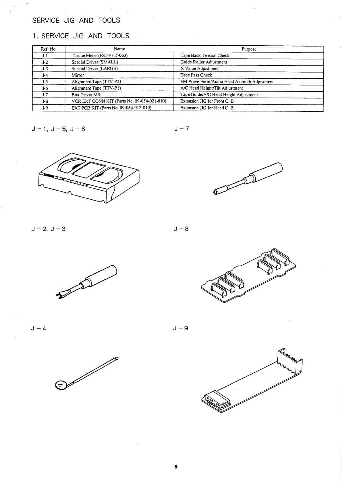
1.
SERVICE
JIG
AND
TOOLS
PU
ee
eRe
eee
eee
eee
eRe
eee
eee
me
mee
heme
eee
eee
ee
eee
ee
eee
ee
meee
ee
eee
eee
eee
ee
5
2.
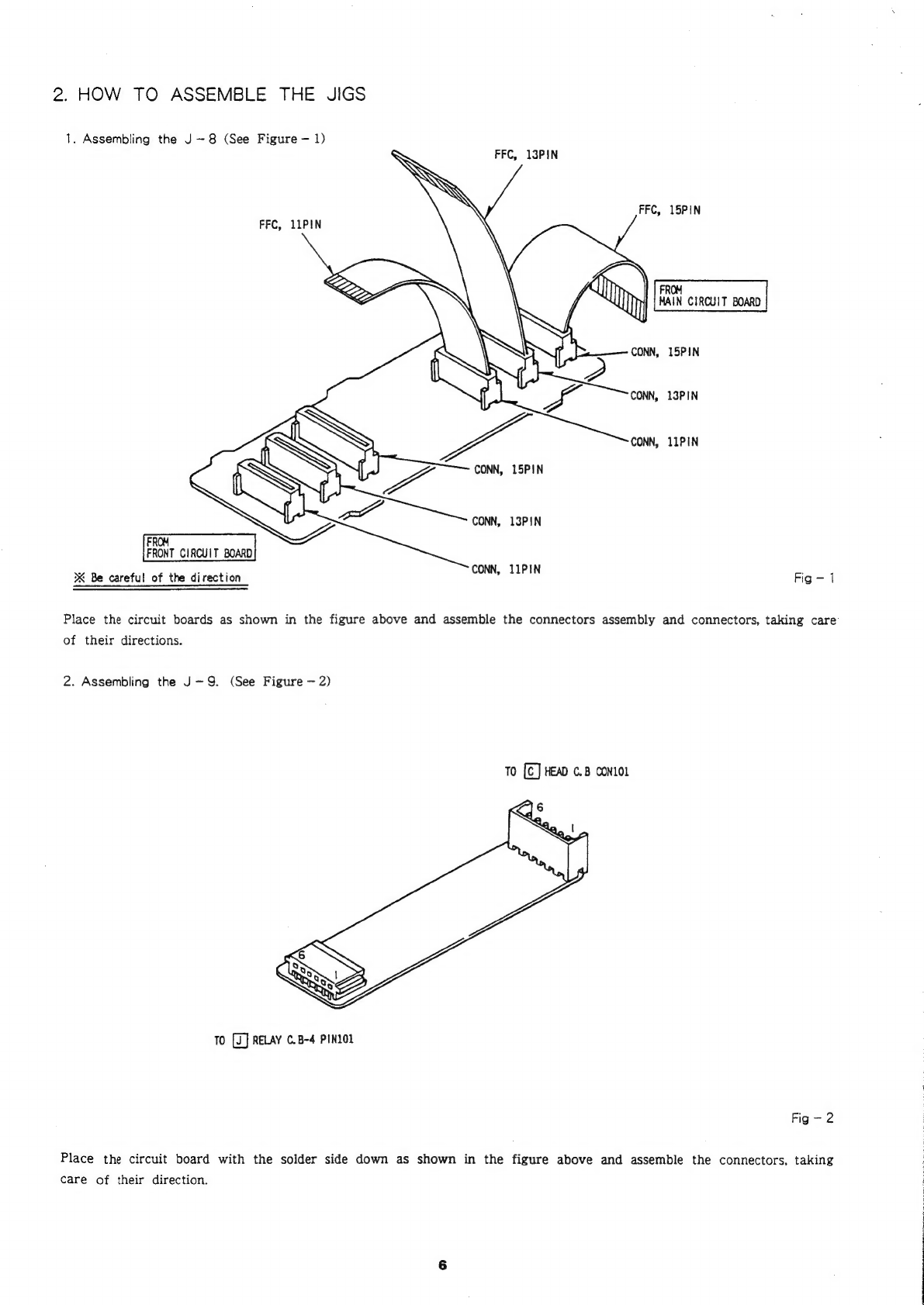
HOW
TO
ASSEMBLE
THE
JIGS
core
crete
tect
tte
ct
tee
ee
eee
ee
renee
meee
eee
eee
ene
e
Ee
eee
eee
ete
teens
6
3.
HOW
TO
USE
THE
JIGS
Cc
7
Mi
DISASSEMBLY.
“INSTRUCTIONS
(oc.04
seuri
ied
cats
ueiides
siieethea
ccae
baesnuiieeeensaslnudases
aval
neseeaae
8~20
MEELECTRICAL
MAIN
PARTS
LIST
.....0.0ceccccccccce
cece
nee
e
eee
eben
eee
n
ete
e
eee
e
esse
eben
betes
eee
e
beeen
nas
21~23
ME
TRANSISTOR
ILLUSTRATION
......00.ccce
cece
cece
cece
cece
cere
ee
eect
ee
be
eee
eeeeeeecteeeeesstenetseneeeeeueeeneres
23
MEPRACTICAL::
SERVICE
FIGURE
xi
escnce
oreetei
wece
sa
tccaeiee
eas
ened
es
sah
Peas
bane
Wiest
suas
oe
atuaalbde
sees
ohe
24
BE
BLOCK
DIAGRAM:
secs
occ
es
dne5
ces
sineitied
ieee
culelete.
dane
ee
sists
semble
eie
tuna
aa
vide
Gh
gies
Sed
Ceiba
de
baile
nie
eare
alate
25~29
.
BLOCK
DIAGRAM
—
1
(VIDEO
SECTION)
PAO
e
eee
ete
eee rem
meee
emer
meer
rece
reer
eee
ree
e
een
arene
eee
eter
etnnse
25~26
+
BLOCK
DIAGRAM
~2
(SERVO//SYSTEM
CONTROL.
SECTION)
-erc
rec
c
eer
ee
ete
ete
eter
ene
tense
tenet
ence
een
ennans
27~28
.
BLOCK
DIAGRAM
=
3
(POWER
UNIT
SECTION)
Ce
29
WWIRE
HARNESS
DIAGRAM
da
eaeRermaenaen
sdaitle
Ml
aaeea
minis
Medina
tauedenal
eauas
Maw
Momus
weenie
ofa%
30~31
BME
WAVE
FORM
—1
(VIDEO
SECTION)
..--.-.-
cece
cece
eect
e
eee
e
cette
eb
eset
teense
eeteeneeevanreeennneeans
vaib
tines
32
MEWIRING
—
1
(VIDEO
“AUDIO
SECTION)
.---.
ccc
cece
cece
cece
ccc
e
eee
n
eee
e
eee
e
eee
ne
ene
teeta
eeneeebaeens
33~36
MEWAVE
FORM
—
2
(VIDEO
SECTION)
.-ccccc
ccc
c
eect
eee
eect
eect
nee
e
ene
ee
ee
eter
ene
n
eee
e
tebe
tebe
eet
eeaaed
37
BMESCHEMATIC
DIAGRAM
—1
(VIDEO
—1
SECTION)
..-..-
ee
cece
eee
ee
cee
eee
e
cence
bent
ee
tn
etnenes
38~39
MESCHEMATIC
DIAGRAM
—
2
(VIDEO
—
2
SECTION)
..---.-.
ccc
cece
eee
cect
ee
cnet
ence
beeen
eee
n
een
eenneenees
40
MESCHEMATIC
DIAGRAM
—
3
(AUDIO
SECTION)
«cece
cece
crete
ese
c
cece
cece
cece
reece
ner
eeererences
41
MEWAVE
FORM
—
3
(SERVO
SECTION)
cece
ccc
cece
reece
cece
cree cece
cee
eee
e
eee
eent
etn
eeceeeeees
42
MESCHEMATIC
DIAGRAM
—
4
(SERVO//SYSTEM
CONTROL
SECTION)
.-------:0:2:0-sseeeee
eee
ee
ee
ees
43~45
BESCHEMATIC
DIAGRAM
—5
(FRONT
SECTION)
.......-..
2c
ccc
cece
cece
cere
cece
net
e
ete
ne ee
een
ee
eten eens
46~47
HESCHEMATIC
DIAGRAM
—6
(HEAD
SECTION)
.....--.:
cee
cece
nec
c
eee
e
cence
nee
eee
een
teste
settee
eeenes
47~48
MI
WIRING
—
2
(FRONT
/HEAD/
MECHANISM
SECTION)
.--.-..--02
cee
cc
ence
eect
ee
ee
eee
nets
eee
e
een
eees
49~50
BB
SCHEMATIC
DIAGRAM
—
7
(POWER
SECTION)
...----0-
cece
cence
cence
cee
cere
cere
een
ee
ene
teen
een
eennes
51~52
MB
WIRING
—
3
(POWER
SECTION)
..----:-
cece
cece
cece
ete
cee
e
nee
e
een
e
eben
eee
ecb
eee
e
tebe
tenn
ener tees
51~52
BESYSTEM:
SWITCH
(MODE?
¢s2ssndncd
ote
Bete
ciate
ine
ey
elale
Ainteg
aR
EN
ena
eas
Ta
Sande
eine
waren
ts
53
WEDRUM
SERVO
SYSTEM
TIMING
CHART
.......--::ccecee
cece
eee
e
eet
ecenneeceeanees
wo
hectare
ahaa
sas
ta
PAL
So
tcle
54
BRIG:
DESCRIPTION
we22icc
season
na
sda
east
tlds
sie
ceed
Lt
eed
DA
Lie
ates
eat
ad
deen
av aw
va
veld
55
@
IC,
u
PD75108CW
—
WO02
BIG.
“BLOCK:
‘DIAGRAM
#26
fs
bind
ee
ea
te
eitiege
na
al
ena
oes
de
hee
ca
ales
ale
wtesen
dale
Sa
cee
nd
bd
owed
AM
56~57
@
IC,
MN67481
JIC,
LC8992/1IC,
LA7311//IC,
BA6219B