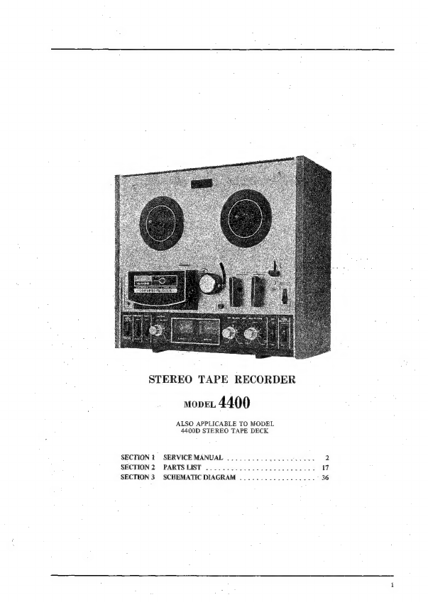
Akai 4400 User manual

STEREO
TAPE
RECORDER
movet
4400
ALSO
APPLICABLE
TO
MODEL
4400D
STEREO
TAPE
DECK
SECTION
1
SERVICE
MANUAL
SECTION
2
PARTS
LIST
SECTION
3
SCHEMATIC
DIAGRAM
..
.

U.
iH.
IV.
Vi.
VIL
SECTION
1
SERVICE
MANUAL
TABLE
OF
CONTENTS
SPECIFICATIONS
MEASURING
METHOD
1,
TAPE
SPEED
DEVIATION
2,
WOW
AND
FLUTTER
3,
FREQUENCY
RESPONSE
.
-
4,
SIGNAL
TO
NOISE
RATIO
.
5
6.
7
8
.
TOTAL
HARMONIC
DISTORTION
FACTOR
.
.
.
CROSS
TALK
(Cross
talk
between
the
tracks)
....
.
ERASE
RATIO
.
POWER
OUTPUT
(4400
only)
DISMANTLING
OF
UNIT
.....--
OPEN
REEL
MECHANISM
ADJUSTMENTS
1,
PINCH
WHEEL
ADJUSTMENT
«0.0.0...
00s
esc
e
cece
rene
ees
2,
SUPPLY
REEL
SHAFT
ASSEMBLY
ADJUSTMENT
3,
TAKE-UP
REEL
SHAFT
ASSEMBLY
ADJUSTMENT.
4,
RECORDING/PLAY
BACK
CHANGING
MECHANISM
HEAD
ADJUSTMENTS
.
.
1,
HEAD
HEIGHT
ADJUSTMENT
.
2.
HEAD
SLANT
ADJUSTMENT
..
3,
HEAD
AZIMUTH
ALIGNMENT
ADJUSTMENT
AMPLIFIER
ADJUSTMENTS
.
. . .
-
1,
PLAYBACK
LEVEL
ADJUSTMENT
.
2,
RECORDING
LEVEL
ADJUSTMENT
bp
est
3,
RECORDING
BIAS
FREQUENCY
ADJUSTMENT
........-.
4,
RECORDING
BIAS
VOLTAGE
ADJUSTMENT
(FREQUENCY
RESPONSE
ADJUSTMENT).
.
13
5,
ERASE
VOLTAGE
DC
RESISTANCE
....
i,
HEAD
DC
RESISTANCE
2,
MOTOR
DC
RESISTANCE
‘VIE.
COMPOSITE
VIEWS
OF
COMPONENTS
......----
5-2-2222
eect
e
centr
eee
ener
16

l..
SPECIFICATIONS
‘An
asterisk
next
to
a
figure
indicates
the
minimum
guaranteed
performance.
TRACK
SYSTEM
4-track
2-channel
stereo
system.
REEL
CAPACITY
Up
to
7”
zeel
TAPE
SPEED
7-1/2
and
3-3/4
ips
22%
(#3%)
WOW
AND
FLUTTER
Less
than
0.15%
(*0.22%)
RMS
at
7-1/2
ips
FREQUENCY
RESPONSE
AKAI
SRT
Tape
1
Less
than
0.20%
{*0.30%)
RMS
at
3-3/4
ips
30
to
23,000
Hz
(*40
to
22,000
Hz)
+3
dB
at
7-1/2
ips
30
to
15,080
Hz
(*40
to
13,000
Hz)
+3
dB
at
3-3/4
ips
Regular
Tape
|
30
to
20,000
Hz
(*40
to
20,000
Hz)
+3
dB
at
7-1/2
ips
30
to
13,000
Hz
("40
to
11,000
Hz)
+3
dB
at
3-3/4
ips
SIGNAL
TO
NOISE
RATIO
‘Better
than
50
dB
at
7-1/2
ips
|__Better
than
48
dB
at
3-3/4
ips
HUM
AND
NOISE
(4400
only)
"Less
than
5
mV
at
minimum
volume
DISTORTION
Less than
1.5%
(#2.0%)
at
7-1/2
ips
Less
than
2.5%
at
3-3/4
ips
CROSS
TALK
Better
than
70
dB
(*60
dB)
monaural
Better
than
50
dB
(745
aB)
stereo
ERASE
RATIO
Better
than
70
dB
INPUTS
Mic
input
|
0.8
mV
Impedance:
5
k2
Line
input
|
70
mV
Impedance:
150
k®
Din
input
|
_7mV
OUTPUTS
Line
output
|
1.228V
(4
#1
dB),
using
a
250
Hz
“O”
VU
recorded
tape
Din
output
|
0.4V
Speaker output
(4400
only)
|
16W
total
music
power
at
82
12W
(*8W)
continuous
power
at
8
BIAS
FREQUENCY,
105
kHz
£5%
BIAS
LEAK
a
Less
than
~30
VU
BIGH
FREQUENCY
DEVIATION
Within
2
dB,
using
an
8,000
Hz
3-3/4
ips
recosded
tape
at
7-1/2
ips
RECORDING
CAPACITY
60
min,
stereo
recording,
using
a
1,200
ft.
tape
at
7-1/2
ips
FAST
FORWARD
AND
REWIND
TIME
152/190
sec.,
using
a
1,200
ft.
tape
at
60/50
Hz
MOTOR
4-pole
induction
L-speed
motor
Type:
SSM-1
Revolutions:
1,800/1,500
rpm.
at
60/50
Hz
HEADS
Recording
Head
|
In-line
4-irack
2-channel
recording
head
|
Type:
P4-154
Gap:
1
micron
Impedance:
959
+15%
at
1,000
Hz
Playback
Head
|
Indine
4-track
2-channel
playback
head
Type:
PA-150
|
Gap:
1
micron
Impedance:
1,250
+15%
at
1,000
Hz
Erase
Head
|
In-line
4-track
2-channel
erase
head
Type:
£4-200
Gap:
0.6
mm
_
i
Impedance:
2002
+5%
at
100
kz
TRANSISTORS
=
2SCSSBLG(Q
(D)...6
28C97i(2)
@)
(red)...
2
2SC871(E)
()...2
28C1098(L)
(M).
ial
LD3141...4
STK-Oi1
..
.
2
(4400
only)
DIODES
a
IN34A...2
TODC-1...1
=
Wz-240...1
os
POWER
SUPPLY
100
to
240V
A.C.,
50/60
Hz
120V
A.C.,
66
Hz
for
CSA/UL
Models
220V
A.C.,
$0
Hz
for
CEE
Models
POWER
CONSUMPTION
60w
DECK:
35W
INSULATION
RESISTANCE
More
than
50
M2.
INSULATION
DURABILITY
1,000V_
A.C,
for
more
than
1
min.
duration
DIMENSIONS
406(W)
x
314(H)
x
194(D)
mm
(15.9%
«
12.4”
x
7.6")
WEIGHT
33.7
kg
(0.1
tbs.)
NOTE:
Specifications
subject
to
change
without
notice.

ll.
MEASURING
METHOD
1.
TAPE
SPEED
DEVIATION
3,
FREQUENCY
RESPONSE
i
440
4400
Frequency
Aig
ara
ae
0
Line
output
counter
requency
put
A
L
input
Line
input
Oscillator
output
Fig.
1
‘As
shown
in
Fig.
1,
connect
a
Frequency
Counter
to
the
Line’
Output
of
Model
4400.
Take
a
frequency
counter
reading
at
the
beginning,
middle,
and end
of
tape
winding
during
playback,
The
maximum
value
of
these
respective
readings
will
represent
tape
specd
deviation.
2.
WOW
AND
FLUTTER
4400
Line
output
Wow
and
Flutter
Meter
input
Method
A
As
stiown
in
Fig.
2,
connect
the
Line
Output
of
Model
4400
to
the
Input
of
a
Wow
and
Plutter
Meter.
Use
a
3,000
Hz
pre-recorded
test
tape
and
take
a
wow
and
flutter
meter
reading
at
the
begin-
ning,
middle,
and
end
of
tape
winding.
The
maximum
value
of
these
respective
readings
will
represent
the
wow
and
flutter.
Method
B
Supply
a
3,000
Hz
sine
wave
signal
from
an
Audio
Frequency
Oscillator
and
make
a
recording
on
a
blank
tape
at
the
beginning,
middle,
and
end
of
tape
winding.
Rewind
and
Playback
tape.
Measure
wow
and
flutter
with
a
Wow
and
Flutter
Meter.
{The
wow
and
flutter
value
of
Method B
will
be
close
to
twice
that
of
Method
A.)
High
Sensitivity
V.T.V.M,
Fig.
3
For
measuring
frequency
response,
connect
instru-
ments
as
shown
in
Fig.
3
and
proceed
as
follows:
1)
Supply
a
1,000
Hz
sine
wave
to
the
Line
Input
of
Model
4400
from
an
Audio
Frequency
Oscil-
lator
through
an
Attenuator.
Set
recorder
to
re-
cording
mode
and
turn
recording
level
volume
control
to
maximum.
Adjust
Attenuator
to
obtain
a
+4
dB
V.T.V.M.
reading.
2)
Under
conditions
described
in
1)
above,
re-adjust
Attenuator
so
that
the
Line
Output
is
—}@
dB,
and
record
40
to
‘20,000
Hz
spot
frequencies.
3)
Rewind
tape
and
playback
from
the
beginning.
Take
V.T.V.M.
spot
frequency
readings
and
plot
values
on
a
graph.
NOTE:
When
measuring
frequency
response,
new
tape
should
be
used.
4,
SIGNAL
TO
NOJSE
RATIO
aaa
|
4400
Line
output
High
Sensitivity
V.T.V.M.
Fig.
4
As
shown
in
Fig.
4,
connect
a
High
Sensitivity
V.T.V.M.
to
the
Line
output
of
Model
4400.
Play-
back
a
250
Hz
“0”
VU
pre-recorded
test
tape
and
measure
the
output.
Then
remove
the
tape
and
measure
the
noise
level
under
the
same
condition.
Convert
cach
of
the
measured
values
into
decibels.

5.
TOTAL
HARMONIC
DISTORTION
FACTOR
4400
Audio
Line
Frequency
ATT,
input
Line
Oscillator
output
Distortion
Meter
Fig.
5
Connect
the
measuring
instruments
as
shown
in
Fig.
5
and
record
a
1,000
Hz
sine
wave
signal
at
“0”
VU.
Playback
the
resultant
signal
and
measure
the
over-
al]
distortion
factor.
Measure
the
noise
level
of
the
tape
recorder
without
the
tape.
Connect
the
Audio
Frequency
Oscillator
directly
to
the
distortion
meter
for
measurement
of
the
distortion
factor
of
the
oscillator.
The
required
distortion
factor
can
be
obtained
from
the
results
of
the
above
measurement
by
the
following
formula:
dy
=d—d,
-
4,
where,
do
=
Required
distortion
factor
d
=
Overall
distortion
factor
”
dy
=
Noise
level
d,
=
Distortion
factor
of
the
oscillator
NOTE:
When
measuring
the
distortion
factor,
new
tape
should
be
used.
6.
CROSS
TALK
(Cross
talk
between
the
tracks)
(TAPE)
mmm
TAPE
DIRECTION
®@@O
Fig.
6
As
shown
in
Fig,
6,
first
record
a
1,000
Hz
sine
wave
signal
on
Track
No.
3
at
+3
VU
level.
Next,
record
under
a
non-input
condition.
Then,
playback
the
tape
on
Tracks
No,
3
and
4
through
the
B.P.F.
(band
pass
filter
sensitivity
.
..
1:1)
and
obtain
a
ratio
between
the
two
from
the
following
formula:
C=
200g
—
Eo
_
(ap)
2
Ey
where,
C
=
Desired
cross
talk
ratio
(dB)
E
,000
Hz
signal
cutput
level
E,
=
1,000
Hz
cross
talk
level
E,
=
Non-input
signal
recorded
level
7.
ERASE
RATIO
‘As
shown
in
Fig.
4,
connect
a
High
Sensitivity
V.T.VM,
to
the
Line
Output
of
Model
4400.
Play-
back
a
virgin
tape
and
take
a
V.T.V.M.
reading
of
the
output
level.
Next,
record
a
1,000
Hz
sine
wave
signal
at
+3
dB,
then
playback
this
recorded
signal
and
take
a
V.T.V.M.
reading
of
the
output
level.
Next,
using
this
pre-recorded
tape,
record
under
a
non-input
condition
and
take
a
reading
of
the
noise
level
output
of
the
erased
signal
and
obtain
a
ratio
between
the
two
from
the
following
formula:
Eo
=
——2___
(dB.
Er
=
20
log:
BE,
(dB)
where,
Er
=
Desired
erase
ratio
(dB)
E,=
1,000
Hz
signal
output
level
E,
=
Non-input
signal
recorded
level
E,
=
Virgin
tape
noise
output
level
8.
POWER
OUTPUT
(4400
only)
4400
82.
“High
Speaker
Sensitivity
output
V.T.V.M.
Fig.
7
As
shown
in
Fig.
7,
connect
an
8Q
dummy
load
resistor
to
the
speaker
output
of
the
recorder
and
connect
this
terminal
to
a
High
Sensitivity
V.T.V.M.
Playback
a
250
Hz
“O”
VU
pre-recorded
test
tape
and
take
a
V.T.V.M.
reading
of
the
output
level.
The
resultant
output
can
be
obtained
from
the
results
of
the
above
measurement
by
using
the
follow-
ing
formula:
=.
EB
aM)
where,
P=
Desired
power
output
(watts)
E=
Measured
voltage
(R.M.S.)
R=
82

Hl.
DISMANTLING
OF
UNIT
In
case
of
trouble,
etc.
necessitating
disassembly,
please
disassemble
in
the
order
shown
in
photographs.
Re-
assemble
in
reverse
order.
*
contro.
knoos
©

12
i
Ae
CONNECTION
PLUGS
&
SPRINGS)
|
13
SOREWS
i
ial
ne
‘
soreWs
14
Fea
&
t
SE
EO
AM®,
BLOCK
15
é
MESH
/AM®.
BLOCK
AMPLIFIER
ADJUSTSE:

Iv.
OPEN
REEL
MECHANISM
ADJUSTMENTS

1.
PINCH
WHEEL
ADJUSTMENT
It
is
important
that
the
pinch
wheel
shaft
be
kept
in
perfect
alignment
with
the
capstan
shaft.
Proper
pinch
wheel
pressure
is
between
1,000
and
1,150
grams
when
the
unit
is
operated
at
the
tape
speed
of
7-1/2
ips.
Any
deviation
from
this
specification
will
result
in
wow
and
flutter.
Check
pinch
wheel
pressure
with
a
spring
scale,
and
if
necessary,
adjust
the
pinch
wheel
load
spring.
2.
SUPPLY
REEL
SHAFT
ASSEMBLY
ADJUSTMENT
(See
Fig.
8
at
left)
Felt
clutch
material
(2)
is
used
between
the
lower
side
of
the
reel
table
base
plate
(1)
and
the
rewind
pulley
(3)
to
protect
recording
tape
from
excessive
tension
during
rewind
operation.
To
check
the
amount
of
friction
of
this
part,
install
a
S-inch
reel
with
a
60
mm
diameter
tape
and
gently
pull
the
end
of
the
tape
upward
with
a
spring
scale.
Adjust
the
conical
spring
(4)
so
that
the
amount
of
tension
is
kept
between
400
and
500
grams.
Other
felt
clutch
material
(5)
is
attached
to
the
supply
roller
(6)
to
provide
proper
slippage
during
FWD
and
REC
operation,
The
procedure
for
checking
friction
of
this
part
is
the
same
as
the
foregoing,
and
between
80
and
100
grams
of
tension
gives
best
results.
Adjust
the
spring
(7)
just
under
the
supply
roller
(6).
When
the
unit
is
set
to
fast
forward
operation,
the
amount
of
friction
will
decrease
to
from
15
to
20
grams.
Check
to
see
whether
this
is
satisfactory.
If
not,
adjust
the
spring
plate
(8)
and
the
pressure
of
the
pulley
(9).
Fig.
9
Fig.
10
z
3.
TAKE-UP
REEL
SHAFT
ASSEMBLY
ADJUSTMENT
(See
Fig.
8
at
right)
Felt
clutch
material
(2)
is
attached
to
the
bottom
side
of
the
reel
table
base
plate
(1)
so
that
the
re-
*
cording
tape
will
not
stretch
during
fast
forward
operation
due
to
excessive
tension.
To
check
the
amount
of
friction
of
this
part,
install
a
5-inch
reel
with
a
60
mm
diameter
tape,
and
gently
pull
the
end
of
tape
upward
with
a
spring
scale.
Adjust
the
conical
spring
(4)
so
that
the
amount
of
tension
at
this
part
is
kept
between
400
and
500
grams.
Other
felt
clutch
material
(10)
is
attached
to
the
take-up
roller
(11).
This
is
to
provide
proper
slippage
during
FWD
or
REC
operation,
The
procedure’
for
checking
friction
of
this
part
is
the
same
as
the
foregoing,
and
between
150
and
180
grams
of
fric-
tion
provides
the
best
results.
Adjust
the
spring
plate
(7)
just
under
the
take-up
roller
(11).
When
the
unit
is
set
to
rewind
operation,
the
amount
of
friction
of
this
part
will
decrease
to
from
15
to
20
grams.
Check
to
see
whether
this
is
satisfactory.
If
not,
adjust
the
spring
(12)
and
the
pressure
of
the
set
sleeve
(13).
4.
RECORDING/PLAYBACK
CHANGING
MECHANISM
(See
Figs.
9,
10)
Turning
the
FWD/REC
knob
(N)
to
recording
posi-
tion
causes
Lever
(a)
to
pull.
Recording
Lever
(b)
(as
illustrated
by
dotted
line),
and
the
FWD/REC
Changing
Switch
(SW-9)
is
turned
to
recording
posi-
tion.
If
Lever
(a)
does
not
pull
Lever
(b)
properly,
Changing
Switch
SW-9
will
not
operate
properly.
This
may
cause
abnormal
oscillation
and
inability
to
record.
In
this
case,
loosen
Screw
(c)
and
adjust
lever.

V.
HEAD
ADJUSTMENTS
Fig,
11
TAPE
ERASE
RECORDING
HEAD
Since
adjustment
of
the
Heads
critically
affects
tape
recorder
performance,
it is
essential
that
Heads
be
carefully
adjusted
with
precision
measuring
equip-
ment
and
suitable
recorded
tape.
1.
HEAD
HEIGHT
ADJUSTMENT
(See
Figs.
11,
12)
1)
Erase
Head
Adjust
height
control
screws
(a),
(b)
by
turning
to
left
and
right
so
that
the
upper
edge
of
the
tape
is
0.15
mm
lower
than
the
upper
edge
of
the
erase
head
core.
2)
Recording
Head
Adjust.
the
screws
(c),
(d)
by
turning
to
left
and
tight
until
the
width
between
the
upper
edge
of
channel
1
head
core
and
upper
edge
of
the
tape
is
equal.
3)
Playback
Head
Adjust
the
screws
(i),
{g)
by
turning
to
left
and
right
until
the
width
between
the
upper
edge
of
channel
1
head
core
and
upper
edge
of
the
tape
is
equal.
PLAYBACK
HEAD
Fig.
12
.
HEAD
SLANT
ADJUSTMENT
(See
Figs,
11,
12)
Adjust
the
screws
(Head
Height.
control
screws)
by
turning
to
left
and
right
so
that
each
head
(Erase,
Recording
and
Playback
Head)
contacts
the
tape
surface
at
a
right
angle.
.
HEAD
AZIMUTH
ALIGNMENT
ADJUSTMENT
(See
Figs.
11,
12)
1)
Playback
Head
Playback
an
Ampex
Alignment
test
tape
(8.000
Hz
3-3/4
ips.)
al
7-1/2
ips.
Adjust
screw
(h)
by
turning
to
feft
and
tight
until
the
various
line
outputs
are
maximum.
2)
Recording
Head
At
recording
mode,
supply
a
15,000
Hz
sine
wave
at
a
—16
dB
recording
level
from
an
Audio
Fre-
quency
Oscillator
to
the
line-input
of
the
4400,
and
set
the
Monitor
switch
to
“TAPE”
position.
Then
adjust
screw
(e)
by
turning
to
left
and
right
until
the
various
Hine
outputs
are
maximum.
4.
Repeat
adjustments
outlined
in
Items
1—2)
to
3,
above
2
or
3
times
to
obtain
optimum
adjusted
condition.
10

Vi.
AMPLIFIER
ADJUSTMENTS
Audio
Oscillator
Output
A
||
:
Line
Line
igh
MONITOR
SW,
sw4
Fig,
15
input
Input
Sensitivity
V.T.VM.
output
Fig.
13
RIGHT
LINE
VR
vR2
LEFT
MIC
VR
EQUALIZER
SW,
Fig.
14
VRI
sw2
.
PLAYBACK
LEVEL
ADJUSTMENT
(See
Figs.
13
to
16)
1)
Set
the
Monitor
switch
to
“TAPE”
position
and
Equalizer
switch
to
7-1/2
ips.
:
2)
In
case
of
4400D,
set
output
VR
(VR3a,
b
10
KB)
to
maximum,
.
3)
Connect
a
High
Sensitivity
V.T.V.M.
to
the
line
output.
4)
Playback
a
250
Hz
pre-recorded
test
tape
at
7-1/2
ips.,
and
adjust
semi-fixed
resistor
VR2
and
VR2b
(20
kB)
to
obtain
a
4
dB
P.B.
level.
(VU
meter
indicates
“0”
VU.)
Recording
Amplifier
Adjustment
should
be
made
only
after
Head
Adjustments
and
Playback
Am-
plifier
Adjustments
have
been
made.
RECORDING
LEVEL
ADJUSTMENT
(See
Figs.
13
to
16)
1)
Set
the
Monitor
switch
to
“TAPE”
position
and
Equalizer
switch
to
7-1/2
ips.
2)
Connect
an
Audio
Frequency
Oscillator
to
the
Jine
input
and
High
Sensitivity
V.T.V.M,
to
the
line
output.
3)
Load
a
Scotch-111
blank
tape
and
set
recorder
to
“REC”
mode.
4)
In
case
of
4400D,
set
output
VR
(VR3a,b
10
kB)
fo
maximum.
5)
Supply
a
1,000
Hz
sine
wave
from
an
Audio
Fre-
quency
Oscillator’
and
adjust
the
line
recording
level
control
volumes
(VR1
and
VR2
50
kB)
until
the
line
output
level
reaches
4
dB.
(VU
meter
indicates
“0”
VU.)
6)
Set
the
Monitor
switch
to
“SOURCE”
position.
7)
Adjust
semi-fixed
resistor-VR1
and
WR1b
(2
kB)
to
obtain
4
dB
recording
level.
(VU
meter
in-
dicates
“0”
VU.)
8)
Repeat
2
times
in
the
same
way
as
indicated
in
Items
5)
to
8)
above.
il

TO
CHASSIS:
FROM
6
aa
TO EQ
SW
(sw2)
TO
MONITOR
Sw
(sw.4)
“ABE
yet
FROM
MONITOR
SW
(Swa)
<o—s4
TO
STEREO
HEAD
tN
PHONE
J9
To
LEFT
UNE
OUTPUT
8
TO
LEFT
ch
Ws
METER
FROM
U6
TO
MONITOR
SW
(sW4)
TO EQ
Sw
(sw2)
FROM
MONITOR
SW
(SW4)
TO
STEREO
“HEAONE
v9.
1
RIGHT
Ab
FPuT
v0
TO
RIGHT
ch
VU
METER
Bw
TO
TARE.
ECTOR
SW(SW3)
1
swo
=
‘TO
MONITOR
SW
(SW4)
Free
Eee
Eek,
=
FROM
VR2
mat
&
To
vR2
FROM
RIGHT
MIC
JACK
U5
TAPE
SELECTOR
SW
(SW3)
To
swe
TO
MONITOR
sw
(Sw4)
FROM
VRI
TO
vRI
FROM
LEFT
MIC
JACK
Ji
Fig.
16
PRE-AMP.
P.C.
BOARD
(LE-5022)

FREQUENCY
COUNTER
Fig.
17
3.
RECORDING
BIAS
FREQUENCY
ADJUSTMENT
(See
Fig.
18)
1)
Set
the
recorder
to
recording
mode.
2)
Connect
a
Frequency
counter
to
points
(A)
and
(C)
in
Fig.
18
of
the
Oscillator
P.C.
Board
(LE-
$021)
and
read
the
frequency
indication.
3)
If
the
bias
frequency
is
105
kHz
+5%,
the
bias
frequency
is
correct.
4)
If
the
bias
frequency
is
incorrect,
it
can
be
ad-
justed
by
changing
the
value
of
condenser
C8
(5600
PF)
of
the
oscillator
P.C.
Board
(LE-5021).
4,RECORDING
BIAS
VOLTAGE
ADJUST-
MENT
(FREQUENCY
RESPONSE
ADJUSTMENT)
(See
Figs.
17,
18)
1)
Set
the
Monitor
switch
to
“TAPE”
position
and
Equalizer
switch
to
7-1/2
ips.
2)
Connect
an
Audio
Frequency
Oscillator
to
the
line
input
through
an
Attenuator
and’
a
High
Sensitivity
V.T.V.M.
to
the
line
output.
3)
Load
a
blank
test
tape
“AKAI
100L”
(Fuji
S-100)
and
set
the
recorder
to
“REC”
mode.
4)
Turn
recording
level
control
volume’
VR1I
and
VR2
($0
kA)
to
obtain
4
dB
V.T.V.M.
reading.
5)
Under
conditions
described
in
Item
4)
above,
readjust
attenuator
so
that
the
line
output
level
is
—16
dB.
6)
Record
from
40
to
20,000
Hz
spot
frequencies.
7)
Adjust
Bias
Adjustment
semi-fixed
condenser
C6
(70
PF
max.)
so
that
the
output
of
1,000
Hz
and
15,000
Hz
frequencies
are
equal.
8)
The
bias
voltage
at
this
time
is
around
11V
A.C,
5.
ERASE
VOLTAGE
1)
Set
the
recorder
to
“REC”
mode.
2)
Connect
a
V.T.V.M.
to
points
(B)
and
(C)
in
Fig.
18
of
the
oscillator
P.C.
Board
(LE-5021)
and
read
the
V.T.V.M.
indication.
3)
The
Erase
Voltage
is
around
52V
A.C.
13

QBvOR'Id
MMV
Bd
OL
TO
PRE
AMP
P,C.
BOARD
‘TRANSFORMER
FROM
Fig.
19
OSC.
POWER
P.C.
BOARD
(LE-5S021)
14

vil.
DC
RESISTANCE
1.
HEAD
DC
RESISTANCE
PB
Heads
oc
Seis
ees
paces
91.59
+102
-
15.32
£102
3.52
412
2.
MOTOR
DC
RESISTANCE
450.n
RESISTOR
(74.n
+100
Fig,
20
15

VIH,.
COMPOSITE
VIEWS
OF
COMPONENTS
MAIN
AMP.
P.C.
BOARD
(LE-5213)
FROM
LEFT
ch.
VOLUME
(VR3b
50KA)
“Jo
RIGHT
ch,
SPEAKER
JACK
—
2
—
sor
x
6
i
€
e
ABO
Boxe
3
8 =
t
an
°
Lk
LE
g
(
.
2
Pease
oe
Le
eo
f
ipa:
ye:
ee
ie
Foon
oe
oy
iN
Bs
Cee
meee
th
FROM
RIGHT
ch.
VOLUME
(VR3b
SOKA)
To
LEFT
ch.
SPEAKER
JACK


HOW
TO
USE
THIS
PARTS
LIST
i.
This
parts
list
is
compiled
by
various
individual
blocks
based
on
assembly
process.
2.
When
ordering
parts,
please
describe
parts
number,
serial
number,
and
model
number
in
detail,
3.
How
to
read
List
-——The
reference
number
corresponds
with
ilustration
or
ph~to
number
of
that
particular
parts
list.
uP
f
~This
number
corresponds
with
the
Figure
Nun
ear
ee
a
«7
number
corresponds
with
the
individual
parts
index
number
;
[in
that
fi
figure.
ens
small
“x”
indicates
the
inability
to
show
that
particular
part
12-115
tin
the
Photo
or
Illustration.
Schematic
Diagram
Number
of
individual
manufactured
part.
(not
required
for
parts
order)
s—~—
Quantity
of
particular
part
required.
Ref,
Parts
No.
Deseription
No.
FLYWHEEL
BLOCK
#13
12-115x
800425
Flywheel
Block
Assy.
Comp,
RUG
13
12-116
244506
Flywheel
Only
12-117x
244754
Felt,
Flywheel
12-118
251324
Main
Metal
Case
12119
253080
Main
Metal
4.
The
symbol
numbers
shown
on
the
P.C.
Board
list
can
be
matched
with
the
Composite
Views
of
Components
of
the
Schematic
Diagram
or
Service
Manual.
5.
The
indications
of
Resistors
and
Capacitors
in
the
photos
of
P.C,
Board
are
being
eliminated,
6.
The
shape
of
the
parts
and
parts
name,
ctc.
can
be
confirmed
by
comparing
them
with
the
parts
shown
on
the
Electrical
Parts
Table
of
P.C.
Board.
7,
Both
the
kind
of
part
and
installation
position
can
be
determined
by
the
Parts
Number.
To
determine
where
a
parts
number
is
listed,
utilize
Parts
Index
at
end
of
Parts
List.
[t is
necessary
first
of
all
to
find
the
Parts
Number.
This
can
be
accomplished
by
using
the
Reference
Number
listed
at
right
of
parts
number
in
the
Parts
Index.
(meaning
of
ref.
no.
outlined
in
Item
3
above).
8.
Utilize
separate
“Price
List
for
Parts”
to
determine
unit
price.
The
most
simple
methad
of
finding
parts
Price
is
to
utilize
the
reference
number.
18s

ELECTRICAL
PARTS
TABLE
‘
2
Stopper
Type|
3
:
i
;
i
f
|
Qe
“St:
j
i
ELECTRICAL
PARTS
LIST
TABLE
REF,
Because
the
indication
of
resistors
and
capacitors
in
the
PLC,
Board
photos
are
being
cliuizate
Insulator
Type
please
confirm
purts
name
and
shape
By
compa
ing
them
with
the
parts
showo
in
this
tobe.
Solid
Resistor
Carbon
Resistor
Metal
Oxide
Fin
Resistor
ry
|
Wire
Wound
Resistor
Thermister
Enamel
Resistor
‘MP
Capacitor
(Tubulet
Type)
Plastic
Capacitor
Mylar
Capacitor
:
VFM
(Hi-Q)
Capacitor
s 6
7
8
Vertical
Type
G
|
ne
#
TS
i
i
j
Mylar
Capacitor
Tantalum
Capacitor
Oil
Capacitor
(Tubaler
Type)
Styrol
Capacitor
9
10
Vertical
Type
u
12
Tubuler
Type
;
See
f
~~
|
Flectrolytic
Capacitor
(Tubuler
Type)
Electrolytic
Capaci
Metalized
Mylar
(Paper)
Capacitor
13
¥oyi-07
Trimmer
Condenser
“Semi-Fixed
Volume
L
TR
rf
Ferti
Inductor
"
Transistor
cR
a)
Spark
Quencher
Diode
{Silicon,
Zener,
Germanium)
19

FIG.
1
ILLUSTRATION
OF
HEAD
BLOCK
This manual suits for next models
1
Table of contents
Other Akai Tape Deck manuals