AKG C 418 III User manual

Bedienungshinweise . . . . . . . . . . . . . . . . . . S. 2
Bitte vor Inbetriebnahme des Gerätes lesen!
User Instructions . . . . . . . . . . . . . . . . . . . . p. 12
Please read the manual before using the equipment!
Mode d’emploi . . . . . . . . . . . . . . . . . . . . . . p. 22
Veuillez lire cette notice avant d’utiliser le système!
Istruzioni per l’uso . . . . . . . . . . . . . . . . . . . p.32
Prima di utilizzare l’apparecchio, leggere il manuale!
Modo de empleo . . . . . . . . . . . . . . . . . . . . p. 42
Antes de utilizar el equipo, sírvase leer el manual!
Instruções de uso . . . . . . . . . . . . . . . . . . . p. 52
Favor leia este manual antes de usar o equipamen
to!
C 418III

2
1.1 Sicherheits-
hinweis
1.2
Lieferumfang
1.3 Empfohlenes
Zubehör
1.4 Besondere
Merkmale
Überprüfen Sie bitte, ob das Gerät, an das Sie das
Mikrofon anschließen möchten, den gültigen Si-
cherheitsbestimmungen entspricht und mit einer
Sicherheitserdung versehen ist.
Kontrollieren Sie bitte, ob die Verpackung alle
oben angeführten Teile enthält. Falls etwas fehlt,
wenden Sie sich bitte an Ihren AKG-Händler.
•Robustes Kondensatormikrofon für Instrumen-
talabnahme auf der Bühne.
•Frequenzgang speziell für die Abnahme von
Schlaginstrumenten ausgelegt.
1 Sicherheitshinweis/Beschreibung
1 C 418III 1 W 44
• Mikrofonkabel MK 9/10: 10 m 2-polig
geschirmtes Kabel mit XLR-Stecker
und XLR-Kupplung
• Phantomspeiseadapter MPA III L
• Batteriespeisegeräte
B 29 L, B 15
• Phantomspeisege-
räte N 62 E,
N 66 E, B 18

3
•Gummiüberzogener Clip zur stabilen Befesti-
gung am Instrument.
•Mikrofonarm mit Schwenkgelenk zur exakten
Ausrichtung des Mikrofons.
•Elastische Lagerung des Wandlersystems zur
wirkungsvollen Körperschallunterdrückung.
•Hohe Rückkopplungssicherheit durch fre-
quenzunabhängige hypernierenförmige Richt-
charakteristik.
Das C 418III ist ein Kondensator-Miniaturmikrofon
mit hypernierenförmiger Richtcharakteristik. Es
wurde speziell für die Abnahme von Schlaginstru-
menten (Snare, Tom-Toms, Roto-Toms) direkt am
Instrument entwickelt.
Eine Bassabsenkung ab 500 Hz verhindert die
Überbetonung der tiefen Frequenzen, die unver-
meidlich entsteht, wenn ein Mikrofon sehr nahe
am Schlagfell befestigt ist. Eine Anhebung der
Empfindlichkeit bei 5 bis 10 kHz sorgt für einen
knackigen Sound.
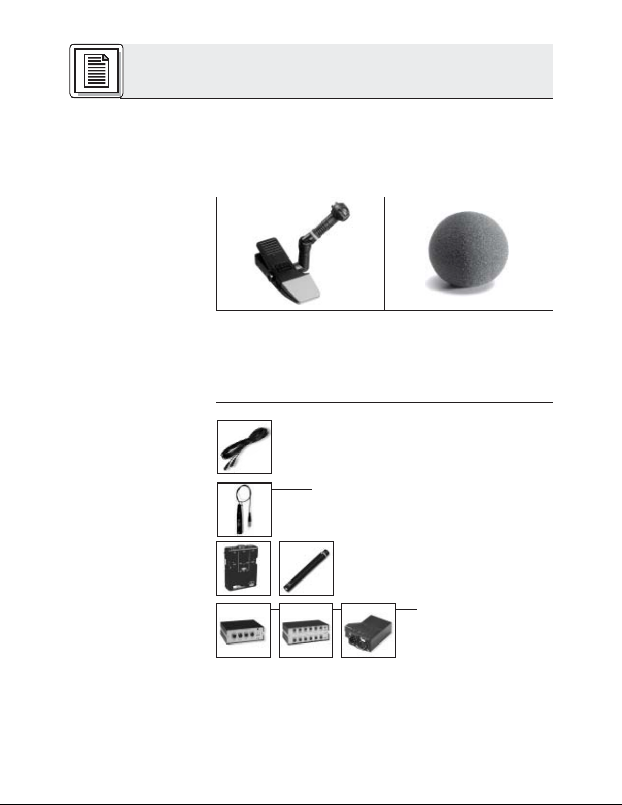
Ein robuster, gummiüberzogener Clip erlaubt die
sichere Befestigung am Instrument. Der Mikrofon-
arm mit Schwenkgelenk ermöglicht eine exakte
Ausrichtung des Mikrofons auf das Schlagfell.
Durch seine hypernierenförmige, frequenzunab-
hängige Richtcharakteristik ist das C 418III beson-
ders unempfindlich gegen Rückkopplungen und
Übersprechen von benachbarten Instrumenten.
Die spezielle elastische Lagerung des Wandlersy-
stems sorgt für eine weitgehende Unempfindlich-
keit des Mikrofons gegen Körperschall und
Schläge mit dem Drumstick.
Ein externer Windschutz für die Dämpfung von
Windgeräuschen bei Einsatz im Freien ist im Lie-
ferumfang enthalten.
1 Beschreibung
1.5 Kurz-
beschreibung

4
1.6 Varianten
C 418III PP
C 418III L
2.1 Einleitung
Wichtig!
2.2 C 418III PP
2.2.1 Anschluss
an symmetri-
sche Eingänge
Das C 418III ist in zwei Ausführungen erhältlich:
•Mit 3-poligem XLR-Stecker mit eingebautem
Adapter für Universal-Phantomspeisung von 9
bis 52 V.
•Mit verriegelbarem Mini-XLR-Stecker zum An-
schluss an Battteriespeisegerät B 29 L, Phan-
tomspeiseadapter MPA III L oder AKG-
Taschensender.
Das C 418III PP/C 418III L ist ein Kondensatormi-
krofon und benötigt daher eine Stromversorgung.
Wenn Sie andere als die von AKG empfoh-
lenen Speisegeräte verwenden, kann das
Mikrofon beschädigt werden und erlischt
die Garantie.
1. Stecken Sie den Phantomspeiseadapter (1) am
Mikrofonkabel an einen symmetrischen XLR-
Mikrofoneingang mit Phantomspeisung an.
2. Schalten Sie die Phantomspeisung ein. (Lesen
2 Anschluss
1 Beschreibung
XLR
1
2
1
3
Phantom
XLR
Abb. 1: Anschluss an symmetrischen Eingang

5
Siehe Abb. 1.
2.2.2 Anschluss
an asymmetri-
sche Eingänge
Siehe Abb. 2.
Hinweis:
Sie dazu in der Betriebsanleitung des jeweili-
gen Gerätes nach.)
3. Wenn Ihr Mischpult keine Phantom-
speisung besitzt, stecken Sie den
Phantomspeiseadapter (1) an ein optionales
AKG-Phantomspeisegerät (2) (N 62 E, N 66 E,
B 18, B 15) an und verbinden Sie das
Phantomspeisegerät mit Hilfe eines XLR-
Kabels (3) (z.B. AKG MK 9/10 - nicht mitglie-
fert) mit einem symmetrischen Eingang.
Phantomspeisegeräte (2) von AKG können Sie auch
an einen asymmetrischen Eingang anschließen.
Verwenden Sie dazu ein Kabel (3) mit XLR-
Stecker (weiblich) und Mono-Klinkenstecker:
1. Verbinden Sie im XLR-Stecker (4) mittels einer
Drahtbrücke Stift 1 mit Stift 3 und mit der
Abschirmung.
2. Verbinden Sie die innere Ader des Kabels mit
Stift 2 des XLR-Steckers (4) und der Spitze
des Klinkensteckers (5).
Beachten Sie, dass asymmetrische Kabel Ein-
streuungen aus Magnetfeldern (von Netz- und
Lichtkabeln, Elektromotoren usw.) wie eine An-
tenne aufnehmen können . Bei Kabeln, die län-
2 Anschluss
XLR Phantom
1
2
3
45
Abb. 2: Anschluss an asymmetrischen Eingang

6
2.3 C 418III L
2.3.1 Anschluss
mittels B 29 L
Siehe Abb.3.
Kabel anstecken:
Kabel abziehen:
Wichtig!
Siehe Abb. 3.
Symmetrischer
Eingang:
Asymmetrischer
Eingang:
ger als 5 m sind, kann dies zu Brumm- und
ähnlichen Störgeräuschen führen.
Mit dem optionalen Batteriespeisegerät B 29 L
können Sie das Mikrofon an symmetrische oder
asymmetrische Eingänge ohne Phantomspeisung
anschliessen.
1. Stecken Sie den Mini-XLR-Stecker (1) am
Mikrofonkabel bis zum Anschlag in eine der
beiden Mini-XLR-Buchsen am B 29 L (2).
Der Stecker (1) verriegelt sich automatisch.
Zum Abziehen des Kabels drücken Sie auf
den Entriegelungsknopf am Mini XLR-Stecker
(1) und ziehen Sie den Stecker (1) aus der
Buchse heraus.
Um das Kabel nicht zu beschädigen, zie-
hen Sie niemals am Kabel selbst!
2. Verbinden Sie das B 29 L (2) mit dem
gewünschten Eingang.
•Zum Anschluss an einen symmetrischen
Eingang verwenden Sie ein handelsübli-
ches XLR-Kabel (3).
•Siehe Kapitel 2.2.2.
2 Anschluss
B 29 L
1
2
3
45
Abb. 3: Anschluss-Schema mit B 29 L

7
2.3.2 Anschluss
mittels MPA III L
Kabel anstecken:
Siehe Abb. 4.
Kabel abziehen:
Siehe Abb. 4.
2.3.3 Anschluss an
Taschensender
1. Stecken Sie den Mini-XLR-Stecker (1) am
Mikrofonkabel bis zum Anschlag in die Mini-
XLR-Kupplung (2) am Anschlusskabel des
MPA III L (3).
Der Stecker (1) verriegelt sich automatisch.
Siehe Kapitel 2.3.1.
2. Stecken Sie den MPA III L (3) an einen sym-
metrischen XLR-Mikrofoneingang mit Phan-
tomspeisung an.
3. Schalten Sie die Phantomspeisung ein. (Lesen
Sie dazu in der Betriebsanleitung des jeweili-
gen Gerätes nach.)
4. Wenn Ihr Mischpult keine Phantom-
speisung besitzt, stecken Sie den MPA III L
(3) an ein optionales AKG-Phantomspeise-
gerät (4) (N 62 E, N 66 E, B 18, B 15) an und
verbinden Sie das Phantomspeisegerät (4) mit
Hilfe eines XLR-Kabels (5) (z.B. AKG MK 9/10
- nicht mitgliefert) mit einem symmetrischen
Eingang.
Lesen Sie in der Bedienungsanleitung Ihres
Taschensenders nach.
2 Anschluss
Mini XLR Mini XLR MPA
MPA
3
Phantom
4
123
5
Abb. 4: Anschluss-Schema mit MPA III L

8
3.1 Einleitung
3.2 Snare Drum
Abb. 5: Befestigung
des Mikrofons an
der Snare Drum
Siehe Abb. 5.
3.3 Tom-Toms,
Roto-Toms
Siehe Abb. 6 und 7.
Hinweis:
Um den ”richtigen” Sound zu finden, müssen Sie
in jedem Fall mit der Mikrofonpositionierung expe-
rimentieren. Als Ausgangspunkt dafür sind in den
folgenden Kapiteln bewährte Mikrofontechniken
beschrieben.
1. Klemmen Sie das Mikrofon am Spannring des
Schlagfells an.
2. Positionieren Sie das Mikrofon:
•Wenn Sie das Mikrofon auf den Rand des
Schlagfells ausrichten, erhalten Sie einen
harten, knackigen Sound.
•Wenn Sie das Mikrofon auf die Mitte des
Schlagfells ausrichten, erhalten Sie einen
volleren, offeneren Sound.
1. Klemmen Sie das Mikrofon am Spannring des
Schlagfells an und richten Sie es wie in Kapitel
3.2 beschrieben aus.
Durch den speziell entwickelten Frequenzgang
des Mikrofons mit einer sanften Bassabsen-
kung ab 500 Hz bis zu einer maximalen Dämp-
fung von 12 dB bei 50 Hz wird ein Nachschwin-
gen des Schlagfells kaum hörbar werden. Ei-
3 Anwendung

9
Abb. 6: Befestigung
des Mikrofons an
Tom-Toms
Abb. 7: Befestigung
des Mikrofons an
Roto-Toms
nen besonders trockenen Sound erhalten Sie,
wenn Sie ein Papiertaschentuch oder ein
Stück Filz mit Klebeband am Rand des Schlag-
fells befestigen.
Reinigen Sie das Gehäuse des Mikrofons mit ei-
nem mit Wasser befeuchteten Tuch.
3 Anwendung
4 Reinigung

10
5 Fehlerbehebung
Fehler
Kein Ton:
Verzerrungen:
Mögliche Ursache
1. Mischpult und/oder
Verstärker ausge-
schaltet.
2. Kanal-Fader oder
Summenpegelregler
am Mischpult oder
Lautstärkeregler des
Verstärkers steht auf
Null.
3. Mikrofon nicht an
Mischpult oder
Verstärker ange-
schlossen.
4. Kabelstecker nicht
richtig angesteckt.
5. Kabel defekt.
6. Keine Speise-
spannung.
1. Gain-Regler am
Mischpult zu weit
aufgedreht.
2. Mischpulteingang zu
empfindlich.
Abhilfe
1. Mischpult und/oder
Verstärker ein-
schalten.
2. Kanal-Fader oder
Summenpegelregler
am Mischpult oder
Lautstärkeregler des
Verstärkers auf ge-
wünschten Pegel
einstellen.
3. Mikrofon an Misch-
pult oder Verstärker
anschließen.
4. Kabelstecker
nochmals an-
stecken.
5. Kabel überprüfen
und falls nötig er-
setzen.
6. Phantomspeisung
einschalten.
Phantomspeise-
gerät: ans Netz
anschließen bzw.
Batterie(n) einlegen.
Kabel überprüfen
und falls nötig er-
setzen.
1. Gain-Regler zurück-
drehen.
2. 10-dB-Vorab-
schwächung
zwischen Mikrofon-
kabel und Eingang
stecken.

11
6 Technische Daten
Arbeitsweise: Kondensatormikrofon mit
Permanentladung
Richtcharakteristik: Hyperniere
Übertragungsbereich: 50 - 20.000 Hz
Empfindlichkeit: 4 mV/Pa (-48 dBV bez. auf 1 V/Pa)
Elektrische Impedanz bei 1000 Hz: 200 Ω
Empfohlene Lastimpedanz: ≥2000 Ω
Grenzschalldruckpegel für 1% / 3% Klirrfaktor: 131 / 140 dB SPL
Äquivalentschalldruckpegel: 38 dB (nach DIN 45412)
Speisespannung: C 418III PP: 9-52 V Universalphantomspeisung
C 418III L: Batteriespeisegerät B 29 L,
Phantomspeiseadapter MPA III L,
AKG WMS Taschensender
Stromaufnahme: ca. 2 mA
Kabellänge/Steckerart: C 418III PP: 3 m / XLR 3-polig
C 418III L: 1,5 m / Mini-XLR 3-polig
Oberfläche: mattschwarz
Abmessungen: 75 x 35 mm
Netto/Bruttogewicht: C 418III PP: 126 g / 448 g
C 418III L: 62 g / 381 g
Dieses Produkt entspricht der Norm EN 50 082-1, vorausgesetzt, dass nachge-
schaltete Geräte CE-konform sind.
Frequenzgang Polardiagramm

12
1.1 Precaution
1.2 Unpacking
1.3 Optional
Accessories
1.4 Features
Please make sure that the piece of equipment
your microphone will be connected to fulfills the
safety regulations in force in your country and is
fitted with a ground lead.
Check that the packaging contains all of the com-
ponents listed above. Should anything be miss-
ing, please contact your AKG dealer.
•Rugged condenser microphone for instrument
miking on stage.
•Frequency response tailored to drum miking.
•Rubber coated clamp for secure attachment to
the instrument.
1 Precaution/Description
1 C 418III 1 W 44
• MK 9/10 microphone cable: 10-m
(30-ft.) 2-conductor shielded cable
w/male and female XLR connectors
• MPA III L phantom power adapter
• B 29 L, B15 battery power
supplies
• N 62 E, N 66 E,
B 18 phantom
power suppplies

13
•Microphone arm with swivel joint for precise
alignment.
•Transducer shock mount reduces handling and
cable noise.
•Frequency-independent hypercardioid polar
response for high gain before feedback.
The C 418III is a miniature hypercardioid condens-
er microphone. It has been specifically designed
for miking up drums (snare drum, tom-toms, roto
toms) directly on the instrument.
A bass rolloff below 500 Hz prevents the kind of
low-frequency overemphasis that would be the
natural consequence of placing a microphone ex-
tremely close to the top head of a drum. A boost in
the microphone's sensitivity between 5 kHz and
10 kHz provides a punchy sound.
A solid, rubber coated clamp will fix the micro-
phone securely on the instrument and the swivel
joint on the microphone arm allows you to align
the microphone exactly with the desired "sweet
spot" on the skin.
The microphone's frequency-independent hyper-
cardioid polar pattern ensures high gain before
feedback and reduces spillover from neighboring
instruments to a minimum. The transducer is sus-
pended in a special shock mount that makes the
microphone highly insensitive to mechanical noise
and drumstick blows.
An external windscreen supplied with the micro-
phone helps reduce wind noise when using the
microphone on an open-air stage.
The C 418III is available in two versions:
•With 3-pin XLR connector with integrated ad-
apter for 9 to 52 V universal phantom power.
•With locking mini XLR connector for use with
the B 29 L battery power supply, MPA III L
1 Description
1.5 Brief
Description
1.6 Versions
C 418III PP:
C 418III L:

14
2.1 Introduction
Important!
2.2 C 418III PP
2.2.1 Connecting
to Balanced
Inputs
Refer to fig. 1.
Refer to fig. 1.
phantom power adapter, or AKG bodypack
transmitters.
The C 418III is a condenser microphone and there-
fore needs a power supply.
Using any power supply other than those
recommended by AKG may damage your
microphone and will void the warranty.
1. Connect the phantom power adapter (1) on the
microphone cable to a balanced XLR micro-
phone input with phantom power.
2. Switch the phantom power on. (Refer to the in-
struction manual of the unit to which you
connected your microphone.)
3. If your mixer provides no phantom power:
Connect the phantom power adapter (1) to an
optional AKG phantom power supply (2) (N 62 E,
N 66 E, B 18, B 15) and use an XLR cable (3)
(e.g., an optional MK 9/10 from AKG) to connect
2 Interfacing
1 Description
XLR
1
2
1
3
Phantom
XLR
Fig. 1: Connecting to a balanced input.

15
2.2.2 Connecting
to Unbalanced
Inputs
Refer to fig. 2.
Note:
2.3 C 418III L
2.3.1 Using the
Optional B 29 L
the phantom power supply to the desired
balanced input.
You may connect any AKG phantom power sup-
ply (2) to an unbalanced input, too.
Use a cable (3) with a female XLR connector and
TS jack plug:
1. On the XLR connector (4), use a wire bridge to
connect pin 1 to pin 3 and the cable shield.
2. Connect the inside wire of the cable to pin 2
on the XLR connector (4) and the tip contact
of the jack plug (5).
Unbalanced cables may pick up interference
from stray magnetic fields near power or lighting
cables, electric motors, etc. like an antenna.
This may introduce hum or similar noise when
you use a cable that is longer than 16 feet (5 m).
The optional B 29 L battery supply allows you to
connect the microphone to balanced or un-
balanced inputs with no phantom power.
2 Interfacing
XLR Phantom
1
2
3
45
Fig. 2: Connecting to an unbalanced input.

16
Connecting the
cable:
Refer to fig. 3.
Disconnecting
the cable:
Important!
Refer to fig. 3.
Balanced input:
Unbalanced input:
2.3.2 Using the
MPA III L
Connecting the cable:
Refer to fig. 4.
Disconnecting
the cable:
1. Push the mini XLR connector (1) on the micro-
phone cable into one of the two mini XLR
sockets on the B 29 L (2) to the stop.
The connector will lock automatically.
To disconnect the cable, press the unlocking
button on the mini XLR connector (1) and pull
the connector (1) out of the socket.
To avoid damaging the cable, never try to
pull out the cable itself!
2. Connect the B 29 L (2) to the desired input.
•Use a commercial XLR cable (3) to connect
the B 29 L (2) to a balanced input.
•Refer to section 2.2.2 above.
1. Push the mini XLR connector (1) on the micro-
phone cable into the mini XLR socket (2) on the
cable of the MPA III L (3) to the stop.
The connector will lock automatically.
Refer to section 2.3.1 above.
2 Interfacing
B 29 L
1
2
3
45
Fig. 3: Using the B 29 L to power the microphone.

17
Refer to fig. 4.
2.3.3 Connecting
to a Bodypack
Transmitter
2. Connect the MPA III L (3) to a balanced XLR
microphone input with phantom power.
3. Switch the phantom power on. (Refer to the in-
struction manual of the unit to which you
connected your microphone.)
4. If your mixer provides no phantom power:
Connect the MPA III L (3) to an optional AKG
phantom power supply (4) (N 62 E, N 66 E, B 18,
B 15) and use an XLR cable (5) (e.g., an optional
MK 9/10 from AKG) to connect the phantom
power supply (4) to the desired balanced input.
Refer to the manual of your bodypack transmitter.
2 Interfacing
Mini XLR Mini XLR MPA
MPA
3
Phantom
4
123
5
Fig. 4: Connection diagram with MPA III L.

18
3.1 Introduction
3.2 Snare Drum
Fig. 5: Fixing the
microphone on a
snare drum.
Refer to fig. 5.
3.3 Tom-toms,
Roto Toms
Refer to figs. 6 and 7.
Note:
The best way to get the ultimate sound is to ex-
periment with various microphone positions. The
following sections describe proven techniques
that you may want to use as starting points for
your own experiments.
1. Clamp the microphone to the top hoop.
2. Align the microphone:
•To get a tight, punchy sound, aim the micro-
phone at the perimeter of the skin.
•To get a rounder, more open sound, aim the
microphone at the center of the skin.
1. Clamp the microphone to the top hoop and
align the microphone referring to section 3.2
above.
The frequency response of the microphone
has been specifically designed to roll off gently
below 500 Hz down to a maximum attenuation
of 12 dB at 50 Hz. This will largely prevent top
head ringing from becoming audible. To get a
very dry sound, you can tape a strip of felt or a
piece of tissue paper to the skin in an off-
center position.
3 Using Your Microphone

19
Fig. 6: Fixing the
microphone on
tom-toms.
Fig. 7: Fixing the
microphone on
Roto toms.
To clean the microphone case, use a soft cloth
moistened with water.
3 Using Your Microphone
4 Cleaning

20
5 Troubleshooting
Problem
No sound:
Distortion:
Possible Cause
1. Power to mixer
and/or amplifier is
off.
2. Channel or master
fader on mixer, or
volume control on
amplifier is at zero.
3. Microphone is not
connected to mix-
er or amplifier.
4. Cable connectors
are seated loosely.
5. Cable is defective.
6. No supply voltage.
1. Gain control on
the mixer set too
high.
2. Mixer input sensi-
tivity too high.
Remedy
1. Switch power to
mixer or amplifier
on.
2. Set channel or
master fader on
mixer or volume
control on ampli-
fier to desired
level.
3. Connect micro-
phone to mixer or
amplifier.
4. Check cable
connectors for se-
cure seat.
5.
Check cable and re-
place if damaged.
6. Switch phantom
power on.
Phantom power
supply: connect to
power outlet or in-
sert battery
(batteries).
Check cable and re-
place if necessary.
1. Turn gain control
down CCW.
2. Connect a 10-dB
preattenuation
pad between
microphone cable
and input.
Table of contents
Languages:
Other AKG Microphone manuals