AKG SOLIDTUBE User manual

SOLIDTUBE
Bedienungshinweise
User Instructions
Mode d´emploi
Istruzioni d´uso
Modo de empleo
Instruções de utilização
For USA and Canada only:
Please observe the “Important Safety Instructions” on page 7!

1. Das Mikrofon
Die SOLIDTUBE wurde aufgrund der großen Nachfrage nach dem
sogenannten „Röhrensound“ in einer für viele erschwinglichen
Preislage entwickelt, wobei selbstverständlich unser besonderes
„know how“ in der Produktion von Großmembranmikrofonen mit
eingeflossen ist.
Es soll an dieser Stelle nicht unerwähnt bleiben, daß die verwendete
Elektronenröhre mit dem eingebauten Heizelement wesentlich
empfindlicher gegen mechanische Stöße ist als die Transistortech-
nik. Deshalb sollte der Verwender dieses Mikrofons immer größte
Sorgfalt und Vorsicht walten lassen. Selbst Stöße, verursacht durch
den Aufprall aus geringer Höhe, können zum Bruch des heißen
Heizfadens und in der Folge zum Totalausfall des Mikrofons führen.
Es ist deshalb ratsam, sich eine in jedem guten Musikfachgeschäft
die zum Beispiel Gitarrenverstärker führen, oder von der nächsten
AKG Servicestelle erhältlichen Ersatzröhre für alle Fälle anzuschaf-
fen und in Reserve zu halten.
Die verwendete Elektronenröhre ist eine ECC 83 (12AX7) und
darfnurgegeneineRöhredergleichenTypegetauschtwerden.
Wie wird die Röhre getauscht?
Vorsicht: Ein Zerlegen des Mikrofons darf nur dann erfolgen, wenn
vorher die Verbindung zum Netzgerät N-SOLIDTUBE gelöst wurde.
Die drei sichtbaren Kreuzschlitzschrauben an der Unterseite
(Steckerseite) des Gehäuses entfernen und die untere Gehäu-
sehälfte soweit vom oberen Gitterkappenteil nach unten schieben,
bis die Elektronenröhre freiliegt. Diese läßt sich nun entfernen, in-
dem der untere Teil der elastischen Lagerung für die Röhre vorsich-
tig weggedrückt wird und gleichzeitig mit einem kleineren, flachen
Schraubendreher die Röhre vorsichtig vom Sockel gehebelt wird.
Das Einsetzen einer neuen Röhre vollzieht sich in umgekehrter Rei-
henfolge der obigen Beschreibung.
Abschließend schieben Sie bitte den unteren Gehäuseteil wieder
nach vorne zum Gitterteil, wobei Sie bitte darauf achten, daß der
Abschwächerschalter freigestellt bleibt, um dann die drei Kreuz-
schlitzschrauben wieder vollständig und fest einzuschrauben.
Sollten Sie Zweifel haben, den oben beschriebenen Arbeits-
vorgang ohne Hilfe durchführen zu können, so wenden Sie
sich bitte vertrauensvoll an die nächstgelegene AKG
Servicestelle.
Wie wird das Mikrofon montiert?
Eine spezielle elastische Halterung „H-Solid“ wurde mitgeliefert
und sollte immer verwendet werden, um das Mikrofon mit Bodensta-
tiven oder Auslegern zu verbinden. Die Klammer der Halterung wird
von unten auf das Mikrofon unter leichtem Drehen soweit aufgescho-
ben, bis der Schriftblock SOLIDTUBE wieder unter der Klammer
sichtbar wird. Damit ist auch ein unabsichtliches Herausgleiten des
Mikrofons aus der Halterung nicht möglich, da der erhabene Schrift-
block einerseits und die im Außendurchmesser vergrößerte Gitter-
kappe andererseits dies verhindern. Das bewußte Entfernen des Mi-
krofons aus der Halterung wird nur durch gleichzeitiges Drehen und
Abziehen des Mikrofonkörpers gegenüber der Halterung möglich.
Nach der Montage des Mikrofons in der Halterung kann diese auf
Stativen oder Auslegern mit Standard 3/8oder 5/8Zoll Gewindestut-
zen aufgeschraubt werden. Die Halterung kann auch gegenüber
der Stativachse geschwenkt werden, um das Mikrofon für die Auf-
nahme optimal auszurichten.
Nur in Ausnahmefällen – zum Beispiel bei Verlust oder Bruch von Teilen
der elastischen Halterung – kann das Mikrofon auch direkt mit seinem
2

3
Nach dem Einschalten der Mikrofonspeisung am Netzgerät erlau-
ben Sie bitte das „Warmwerden“ der Röhre für einige wenige Minu-
ten, um danach den vollen, warmen „Röhrensound“ zu erhalten.
Sollten Sie das Mikrofon an extrem lauten Schallquellen, wie z. B.
vor Lautsprechern von Gitarrenverstärkern, o. ä. verwenden wollen,
so empfiehlt es sich, den am Mikrofongehäuse angebrachten
Dämpfungsschalter nach unten in die Position –20 dB zu schieben.
Damit können Sie sicher sein, daß etwaige Verzerrungen nicht vom
Mikrofon kommen, sondern entweder von der Schallquelle selbst
oder von den dem Mikrofon nachgeschalteten Geräten, wie z. B.
Eingangsstufen von Mischpulten, o. ä. herrühren.
2. Das Netzgerät N-SOLIDTUBE
SICHERHEITSHINWEISE: Nur für trockene Räume. Das Gerät
darf Tropf- oder Spritzwasser nicht ausgesetzt werden. Objekte,
die Flüssigkeiten enthalten (wie z. B. Vasen) dürfen nicht auf oder
in unmittelbarer Nähe dieses Geräts aufgestellt werden.
Das Netzgerät versorgt die Elektronenröhre nicht nur mit Heiz- und
Anodenspannung, sondern beinhaltet auch die Baßabschwächung
des Mikrofons bei etwa 100 Hz, um eventuelle tieffrequente Stör-
schallanteile ausfiltern zu können. Der Bedienknopf dafür befindet
sich auf der Vorderseite des Netzgeräts.
Für externe Verdrahtungen dürfen nur die dafür in dieser Anleitung
empfohlenen Zubehörkabel verwendet werden.
BITTE DRINGEND BEACHTEN!
Im N-SOLIDTUBE kommen gefährliche Spannungen vor. Das
Öffnen des Netzgeräts ist daher unbedingt nur qualifiziertem
Service-Personal zu überlassen. Auf jeden Fall muß vor dem
am Gehäuseunterteil befindlichen Schraubadapter an Stative oder
Auslegern aufgeschraubt werden. Dabei geht natürlich die körper-
schalldämmendeWirkungderHalterung verloren.Essolltedaher mög-
lichst rasch für Ersatz dieses wichtigen Zubehörteils gesorgt werden.
Speisung des Mikrofons:
Das für die Speisung erforderliche Netzgerät „N-SOLIDTUBE“ ist
im Lieferumfang enthalten. Es ist an den Steckertypen und Markie-
rungen an der Gehäuserückseite des Netzgeräts leicht zu erken-
nen, wie das Mikrofon an das Netzgerät angeschlossen werden
soll. Dazu verwenden Sie bitte ausschließlich das ebenfalls im Lie-
ferumfang enthaltene 10 m lange Vielpolkabel „MK-SOLID“. Die
NF kann ebenfalls am Netzgerät symmetrisch mittels einer XLR-3
Steckverbindung abgenommen werden.
Zum Betrieb des Mikrofons:
Die SOLIDTUBE ist mit einer Großmembrankapsel mit nierenförmi-
ger Richtcharakteristik ausgestattet, die damit fast alle in Aufnah-
mestudios vorkommenden Aufgaben lösen wird.
Obwohl das Mikrofon mit einem eingebauten Popschutz versehen
wurde, sollte vor allem bei der Verwendung als Gesangsmikrofon
entweder ein ausreichender Besprechungsabstand von wenig-
stens 20 bis 30 cm eingehalten werden, oder der mitgelieferte und
aufschiebbare Wind/Popschutz „W-SOLID“ zum Einsatz kommen
um unerwünschte Popgeräusche auf die empfindliche Mikrofon-
membran zu verhindern.
Eine weitere Möglichkeit Popgeräusche zu verhindern besteht
durch den Einsatz des optional erhältlichen Studio-Popfilters
PF 80 von AKG.

Öffnen unbedingt der Netzstecker von der Netzsteckdose
gezogen werden.
Vor der Inbetriebnahme des Netzgeräts überzeugen Sie sich
bitte von der ortsüblichen Netzspannung und vergleichen Sie diese
mit dem eingestellten Wert am Spannungswähler des Geräts (ne-
ben dem Netzschalter). Sollte eine Umschaltung der akzeptierten
Betriebsspannung notwendig sein, so kann dies mit einem kleinen
Flachschraubendreher sehr leicht durchgeführt werden:
Setzen Sie den Schraubendreher in die dafür vorgesehene Kerbe am
Sicherungshalter, drücken Sie die federnde Zunge leicht nach rechts
in Richtung Spannungsanzeige und hebeln Sie dabei die ganze Si-
cherungshalterung aus der Fassung. Danach ziehen Sie bitte den
hellen Kunststoffteil mit der Sicherung aus dem Trägerteil, drehen
den Sicherungseinsatz um 180° und setzen ihn wieder in den Träger-
teil ein bis er einrastet. Im Sichtfenster müßte nun die gewünschte
Netzspannung erscheinen. Nun kann der komplette Trägerteil wie-
der in die Fassung eingesetzt werden, bis auch diese einrastet.
Genauso können Sie vorgehen, sollte einmal die Gerätesicherung
zu Schaden kommen.
WARNUNG: Die eingebaute Sicherung darf nur durch eine ge-
normte Sicherung gleichen Typs ersetzt werden. Eine Nichtbe-
achtung dieser Vorschrift kann zu unzulässiger Erwärmung und
Brandgefahr führen.
Sollte in einem Land, in dem das Gerät in Betrieb zu nehmen ist, ein
anderer Netzstecker üblich sein, so müßten Sie ein komplettes
Netzkabel, das den internationalen Sicherheitsbestimmungen ent-
spricht und einen Stecker mit Gerätemasse besitzt, in diesem Land
beschaffen und verwenden.
Dieses Gerät darf nur mit einer mit Schutzerde ausgerüsteten, ge-
normten Netzsteckdose verbunden werden. Die Unterbrechung
des Schutzleiters oder die Montage eines nicht normenkonformen
Steckers ist verboten.
Wenn alle vorangegangenen Überprüfungsschritte erfolgt sind, das
Verbindungskabel zwischen Mikrofon und Netzgerät angesteckt
wurde, die NF-Verbindung zum nachgeschalteten Gerät mittels
Standard – Audiokabel erfolgte und das angesteckte Netzkabel mit
einer Netzbuchse verbunden wurde, müßte nach Einschalten des
Netzschalters am Netzgerät sowohl die Kontrolleuchte an der Vor-
derseite des Netzgeräts aufleuchten als auch am Mikrofon selbst
durch das Sichtfenster (AKG-Logo) die Röhrenheizung rot-orange
glühen. Damit ist im wesentlichen Ihr Mikrofon betriebsbereit.
Zur Beachtung: Manchmal kann durch Erdschleifen auch ein
leichtes Brummgeräusch am NF-Ausgang auftreten, das in erster
Abhilfe mit der „Ground Lift“-Taste neben der NF-Ausgangs-
buchse am Netzgerät eventuell beseitigt werden kann. Diese Taste
unterbricht im gedrückten Zustand die Verbindung vom Stift 1 der
XLR-Buchse zum Null-Volt / Masseniveau des Netzgeräts.
Sollte diese Maßnahme keine Abhilfe für die eingestreute Brumm-
störung ergeben, so müßten Sie in gewohnter Weise die Ursache
der Störung in der restlichen Tonanlage lokalisieren und beseitigen.
Reinigungshinweise:
Alle Oberflächen können von Zeit zu Zeit problemlos mit (Industrie-)
Spiritus oder Alkohol gereinigt werden. Der Schaumstoff-Wind-
schutz wird am besten mit einer milden Waschmittellösung gerei-
nigt und ist sofort nach dem Trocknen wieder einsatzbereit.
Vorab entfernen Sie bitte das Netz-
anschlußkabel vom speisenden Netz!
4

5
3. Technische Daten
Arbeitsweise: Großmembran-Druckgradient-Mikrofon mit Röhren-Vorverstärker
Richtcharakteristik: Niere
Empfindlichkeit bei 1000 Hz: 20 mV / Pa Ⳏ–34 dBV bez. auf 1 V / Pa
Übertragungsbereich: 20–20.000 Hz ± 2,5 dB von Sollkurve
Elektrische Impedanz: 200 Ohm ± 25%
Empfohlene Lastimpedanz: 1000 Ohm
Vorabschwächung: schaltbar auf 0 dB und –20 dB
Baßabschwächung: bei 100 Hz 12 dB / Oktave, einschaltbar am Netzgerät
Ersatzgeräuschpegel nach DIN 45405 (CCIR 468-2): 30 dB
Äquivalentschalldruckpegel nach DIN 45412 (A-bew.): 20 dB-A
Geräuschpegelabstand bezogen auf 1 Pa (A-bew.): 74 dB
Grenzschalldruck für k = 3%: 63 Pa Ⳏ130 dB SPL / 355 Pa Ⳏ145 dB SPL
(Vorabschwächung 0 / –20 dB)
Speisung: mit dem im Lieferumfang enthaltenen Netzgerät N-SOLIDTUBE über
115/230 VAC, ±15/–10% (50–60 Hz)
Steckverbindung: 6 pol. XLR
Äußere Abmessungen: 63/57 Ø x 219 mm
Gewicht: 920 g, netto
Bruttogewicht, inkl. Verpackung: 5,0 kg, inkl. Zubehör und Tragekoffer
Dieses Produkt entspricht den Bestimmungen der europäischen Richtlinien für elektrische Sicherheit und elektromagnetischer
Verträglichkeit nach den angewandten Normen EN 61 000-6-1:2001, EN 61 000-3-3:2001, EN 60 065:2002, sowie UL 6500.

6
Frequenzkurve Polardiagramm
Mitgeliefertes Zubehör: Empfohlenes Zubehör:
N-SOLIDTUBE, Netzgerät PF 80, Studio Popschutzfilter
MK-SOLID, 10 m Anschlußkabel St 102 A, Bodenstativ
H-SOLID, Elastische Halterung St 200, Bodenstativ
W-SOLID, Schaumstoffwindschutz
EUR-Netzkabel
US-Netzkabel
Stabiler Transportkoffer

1. The Microphone
The SOLIDTUBE was developed because of the great demand for
the so-called “tube sound” in a price range suitable for many people,
to which it goes without saying that our special know-how in the pro-
duction of large-diaphragm microphones has had its influence.
It should be stressed at this point that the vacuum tube used with its
inbuilt heater element is significantly more sensitive to mechanical
shocks than is transistor technology. Therefore, the user of this
microphone should always exercise the greatest care and attention.
Even shocks caused by falls from low levels can lead to the breaking
of the hot heating element and, consequently, to the total failure of
the microphone. It is advisable, therefore, to buy and keep in reserve
a spare tube which you can get in any good music shop which sells,
for example, guitar amplifiers, or in the next AKG Service Center.
The microphone incorporates an ECC 83 (12AX7) vacuum tu-
be. Be sure to use replacement tubes of the same type only.
IMPORTANT SAFETY INSTRUCTIONS
Please read, follow and keep these instructions for later con-
sultations. Please heed all warnings for your own safety!
Do not block any ventilation openings on the power supply
unit and do not install the unit near any heat sources such as
radiators, heat registers, stoves, or other apparatus (includ-
ing amplifiers) that produce heat!
Do not use this device near water!
Clean the power supply unit from time to time with a damp
cloth only!
Do not defeat the safety purpose of the grounding type plug on
the power cord! A grounding type plug has two blades and a
third grounding prong. This third prong is provided for safety.
When the provided plug does not fit into your power outlet,
consult an electrician for replacement of the obsolete outlet.
Should another type of power plug be usual in a country in
which the unit is to be operated then you should buy and use
in that country a complete power cord which complies with
the international safety regulations and which has a plug with
device grounding!
Protect the power cord from being walked on or pinched par-
ticularly at plugs and convenience receptacles.
Use only attachment/accessories specified by the manufac-
turer!
Unplug this apparatus during lighting storms or when unused
for long periods of time!
Refer all servicing to qualified service personnel. Servicing is
required when the apparatus has been damaged in any way,
such as power-supply cord or plug is damaged, liquid has
been spilled or objects have fallen into the apparatus, the ap-
paratus has been exposed to rain or moisture, does not op-
erate normally, or has been dropped.
CAUTION: RISK OF FIRE!
Should the fuse in the power supply unit ever be damaged,
replace with the same Type "T 0.125A, 250V" fuse!
7

How is the tube replaced?
IMPORTANT: Prior to disassembling the microphone, make sure
to disconnect the microphone from the N 12 VR power supply.
Remove the three Philips head screws visible on the underside
(connector side) of the housing and push the lower half of the hous-
ing downwards so far from the upper grid cap part until the vacuum
tube is exposed. This can now be removed by carefully pushing
away the lower part of the elasticated cushioning for the tube and,
simultaneously, carefully levering the tube out of the socket with a
small flat screwdriver.
Inserting a new tube is done in reverse order of the above description.
Finally, please push the lower part of the housing forwards again to
the grid part and, while doing so, take care that the attenuator
switch remains free so that the three Philips head screws can be
screwed in again fully and tightly.
If you should have doubts as to whether you can carry out
the procedure described above without help then consult
with confidence the nearest AKG Service Center.
How is the microphone mounted?
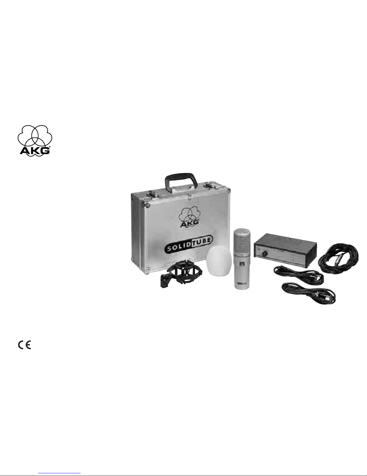
A special elastic shockmount – “H-Solid” is supplied and
should always be used to connect the microphone to floor stands
or booms. The clamp of the shockmount is pushed on to the micro-
phone from below while turning gently until the SOLIDTUBE type
block can be seen again below the clamp. This makes it impossible
for the microphone to slide out of the mounting unintentionally be-
cause this is prevented, on the one side, by the raised type block
and, on the other side, by the grid cap with its larger external diame-
ter. Intentional removal of the microphone from the shockmount is
then only possible by simultaneously turning and pulling the micro-
phone body away from the shockmount.
After fitting the microphone into the shockmount, it can be screwed
on to stands or booms with standard 3/8or 5/8inch threaded
connections. It may also be swivelled against the stand axis in order
to position the microphone optimally for recording.
Only in exceptional cases – for example, on loss or breakage of parts
ofthe elastic shockmount– should themicrophonebe screwed on to
stands or booms directly with the screw adapter on the lower part of
the housing. By doing this, the impact sound absorbing effect of the
shockmount is, naturally, lost. Therefore, replacement of this import-
ant accessory part should be obtained as quickly as possible.
Powering the microphone:
The “N-SOLIDTUBE” power supply unit needed for the powering
is included in the delivery. From the type of connector and the mark-
ings on the rear of the power supply unit housing, it is easy to see
how the microphone should be connected to the power supply. For
this, please use only the 10 m (30 ft.) long multi-core cable
“MK-SOLID” which is likewise included in the delivery. The audio
can likewise be taken balanced from the power supply unit by
means of an XLR-3 connector.
On the operation of the microphone:
The SOLIDTUBE is equipped with a large diaphragm capsule with
cardioid characteristics which can thus handle nearly all tasks oc-
curring in recording studios.
Although the microphone is provided with an built-in pop screen, an
adequate distance to the microphone of at least 20 to 30 cm (ap-
prox. 1 ft.) should be maintained, or the “W-SOLID” wind/pop
screen supplied should be used in order to prevent unwanted
popping noises on the sensitive microphone diaphragm, especially
when using the microphone for singing.
Another way to prevent popping noises is by using the Studio-
Popfilter PF 80 which can be obtained as an option from AKG.
After switching on the microphone power on the power supply unit,
8

9
please allow a few minutes for the tube to warm up so as to get the
full, warm “tube sound”.
If the microphone should be used with extremely loud sources of
sound e.g. in front of guitar amplifier speakers etc., then it is advisa-
ble to push the attenuation switch on the microphone housing
downwards to the –20 dB position. With this you can be certain that
any distortions do not come from the microphone but either from
the sound source itself or from the equipment connected after the
microphone such as, for example, input stages of mixing consoles
or other causes.
2. The N-SOLIDTUBE Power Supply Unit
SAFETY INSTRUCTIONS: Use the equipment in dry rooms only.
Do not expose the equipment to rain or splash water. Never place
objects containing liquids (e.g., vases) on or near the equipment.
The power supply unit does not only supply the vacuum tube with
heater and anode voltage but also contains the switchable bass cut
for the microphone at about 100 Hz in order to be able to filter out
possible low frequency interference noise components. The control
knob for this is found on the front of the power supply.
For any external wiring, do not use any cables other than those re-
commended in this manual.
PLEASE OBSERVE CLOSELY!
Dangerous voltages occur in the N-SOLIDTUBE. Opening the
mains unit must definitely, therefore, be done only by qualified
service personnel. WARNING: Parts inside the equipment
may carry dangerous voltages. Make sure to disconnect the
equipment from power before opening the equipment!
Before starting-up the power supply unit please satisfy yourself
about the local mains voltage and compare this with the value set
on the unit’s voltage selector (next to the power switch). If a change-
over of the accepted operating voltage should be necessary then
this can be done very easily with a small flat-bladed screwdriver.
Before doing this, please remove the
mains connection cable from the
mains supply!
Place the screwdriver in the notch provided for this on the fuse hold-
er, press the spring-loaded tongue gently to the right in the direction
of the voltage indicator and lever the whole fuse holder out of the
socket. Then, please pull the light plastic part with the fuse out of
the carrier part, turn the fuse link through 180º and insert it again in
the carrier part until it engages. The desired mains voltage should
now appear in the window. The complete carrier part can then be
inserted into the socket again until this also engages.
You can also proceed in exactly the same way should the unit fuse
ever be damaged.
WARNING: Make sure to replace the built-in fuse with a standard
fuse of the same type only. Using any other type of fuse may cause
excessive heating and/or a risk of fire.
Should another type of power plug be usual in a country in which
the unit is to be operated then you should buy and use in that coun-
try a complete power cable which complies with the international
safety regulations and which has a plug with device grounding.
Prior to connecting the equipment to power, check that the power
outlet is a standard type with a protective ground connection. Dis-
connecting the protective ground lead or using non-standard po-
wer plugs or non-standard power outlets is illegal.
If all the above checking steps have been completed, the connecting
cable has been plugged in between the microphone and the power
supply, the audio connection to the after-connected equipment has
been made with standard audio cable, and the plugged-in power cable

has been connected to a power socket, then both the control light on
the front of the power supply should light up after switching on the
power supply unit mains switch and also the tube’s heating element
should glow red-orange through the window (AKG logo) on the micro-
phone itself. With this the microphone is essentially ready for operation.
Note: A gentle humming noise can sometimes occur on the audio
output due to ground loops which, as an initial remedy, can possibly
be removed with the “Ground Lift” switch by the audio output
socket on the power supply. When pressed, this switch interrupts
3. Technical Specifications
Operating principle: Large diaphragm pressure gradient microphone with vacuum tube preamplifier
Directional characteristics: Cardioid
Sensitivity at 1000 Hz: 20 mV / Pa Ⳏ–34 dBV re. 1 V / Pa
Frequency range: 20–20,000 Hz ± 2.5 dB from published curve
Electrical impedance: 200 ohms ± 25%
Recommended load impedance: 1000 ohms
Pre-attenuation: Switchable to 0 dB and –20 dB
Bass cut: At 100 Hz 12 dB / octave, can be switched-on on the mains unit
Equivalent noise level conforming to DIN 45405 (CCIR 468-2): 30 dB
Equivalent noise level conforming to DIN 45412 (A-weighted): 20 dB-A
Signal-to-noise ratio ref. 1 Pa (A-weighted): 74 dB
Max. sound pressure for k = 3%: (pre-attenuation 0/–20 dB) 63 Pa Ⳏ130 dB SPL / 355 Pa Ⳏ145 dB SPL
Powering: With the delivered N-SOLIDTUBE power supply unit via 115 / 230 VAC,
±15/–10% (50–60 Hz)
Connector: 6 pin XLR
External dimensions: 63/57 Ø x 219 mm (2.5/2.25 Ø x 8.6 inch)
Weight: 920 g (2 lbs.) net
Gross weight incl. packaging: 5.0 kg (11 lbs.) incl. accessories and travelling case
This product conforms to the specifications of the European Union EMC and Low Voltage Directives in accordance with applied
standards EN 61 000-6-1:2001, EN 61 000-3-3:2001, EN 60 065:2002, as well as UL 6500.
10
the connection from pin 1 of the XLR socket to the zero volt /
ground level of the power supply unit.
Should this measure provide no remedy for the interfering hum
then you must locate and remove the cause of the interference
from the rest of the sound system in the usual way.
Cleaning information:
All surfaces can be cleaned from time to time with (industrial) methyl-
ated spirits or alcohol. The foam windscreen is best cleaned with a
mild detergent solution and is immediately ready for use when dry.

11
Frequency Response Curve Polar Response Curve
Included Accessories: Recommended Accessories:
N-SOLIDTUBE, Power supply unit PF 80, Pop screen filter
MK-SOLID, 10 m (30 ft.) connecting cable St 102 A, Floor stand
H-SOLID, Elastic shockmount St 200, Floor stand
W-SOLID, Foam windscreen
EUR-power cable
US-power cable
Robust carrying case

12
1. Le microphone
La demande pour le son dit de “tube” étant importante, on a déve-
loppé le SOLIDTUBE dans une catégorie de prix accessible à tous
tout en puisant dans notre large expérience en matière de fabrica-
tion de microphones à grande membrane.
Dans ce contexte, il ne faut toutefois pas oublier que le tube électro-
nique employé, dans lequel est intégré un élément de chauffage,
est beaucoup plus sensible aux chocs mécaniques que les transi-
stors. Pour cette raison, l’utilisateur de ce microphone devra tou-
jours le manipuler avec précaution et le plus grand soin. Même un
choc reçu lors d’une chute à faible hauteur est susceptible de rom-
pre le filament incandescent et de provoquer une panne totale du
micro. Voilà pourquoi nous vous conseillons de vous procurer un
tube de réserve à titre de précaution auprès d’un magasin de musi-
que spécialisé revendant des amplificateurs pour guitare par exem-
ple ou auprès du point de vente AKG le plus proche.
Le tube électronique utilisé est un tube ECC 83 (12AX7) et ne
peut être remplacé que par un tube de même type.
Comment remplacer le tube électroni-
que?
ATTENTION: N’oubliezjamaisde débrancher lemicrophonedubloc
secteur N 12 VR avant de commencer à démonter le microphone.
Enlevez les trois vis à fentes en croix visibles sur la partie inférieure
(côté prise) du boîtier et poussez la moitié inférieure du boîtier vers le
bas pour l’éloigner du culot de grille supérieur jusqu’à ce que le
tube électronique soit découvert. Pour le retirer, il faut écarter avec
précaution le bas du logement élastique dans lequel il se trouve tout
en soulevant doucement le tube avec un petit tourne-vis plat de
manière à le sortir du socle.
Pour mettre en place le tube neuf, suivez dans le sens inverse les
étapes décrites ci-dessus.
Veuillez ensuite pousser vers l’avant la partie inférieure du boîtier en
direction de la grille tout en veillant à ce que le bouton du modérateur
reste libre, puis revissez et serrez bien les trois vis à fentes en croix.
Si vous pensez ne pas pouvoir effectuer seul les opérations
décrites ci-dessus, n’hésitez pas à vous adresser à votre
point de vente AKG le plus proche.
Comment monter le micro?
On vous a fourni avec votre micro une attache élastique spéciale,
“H-Solid” , qu’il faudra toujours utiliser pour fixer le micro sur un pied
ou une perche. Faites glisser par en bas la bride de fixation de l’atta-
che sur le micro en la tournant légèrement jusqu’à ce que l’inscripti-
on SOLIDTUBE soit de nouveau visible sous la bride. De cette ma-
nière, le microphone ne peut pas glisser inopinément hors de l’atta-
che vu que l’inscription en relief d’une part et le culot de grille dont le
diamètre extérieur est plus grand, d’autre part, le retiennent. Pour
sortir le micro de l’attache, on est obligé de tourner le corps du micro
tout en le tirant dans la direction opposée à l’attache.
Après avoir monté le microphone dans l’attache, vous pouvez la
visser sur un pied ou une perche pourvus d’un filet normalisé de 3/8
ou 5/8pouces. Il est également possible de faire pivoter l’attache sur
l’axe du pied de façon à trouver l’orientation optimale du micro pour
la prise de son.
On pourra aussi visser directement le microphone sur un pied ou
une perche au moyen du raccord fileté se trouvant sur la partie in-
férieure du boîtier. Toutefois, on ne recourra à cette solution que
dans des cas exceptionnels, de perte ou de détérioration de certai-
nes pièces de l’attache élastique par exemple, car il est évident
qu’on perd ainsi l’effet de l’attache comme amortisseur du bruit de
structure. Pour cette raison, veillez à remplacer le plus rapidement
possible cet accessoire très important.

jusqu’à la position –20 dB. De cette manière, vous pouvez être sûrs
que les distorsions éventuelles ne proviennent pas du micro mais de
la source sonore elle-même ou des appareils situés en aval du micro,
les étages d’entrée des pupitres de mélange par exemple.
2. Le bloc d’alimentation secteur
N-SOLIDTUBE
CONSIGNES DE SÉCURITÉ: Ne peut être utilisé que dans un lo-
cal sec. L’appareil ne doit en aucun cas être exposé aux projections
d’eau ou à de l’eau qui goutte. Ne jamais poser d’objets contenant
un liquide (p.ex. vases) sur l’appareil ou à proximité de celui-ci.
Le bloc d’alimentation secteur ne sert pas seulement à alimenter le
tube électronique en tension de chauffage et en tension anodique,
mais comprend également le dispositif d’atténuation des basses à
100 Hz environ qui permet de filtrer les bruits à basse fréquence
éventuels. A cet effet, le bouton de commande se trouve sur la par-
tie avant du bloc d’alimentation secteur.
Pour les câblages externes, on utilisera exclusivement les câbles
figurant sur la liste des accessoires donnée dans le présent mode
d’emploi.
ATTENTION !!!
Il existe des tensions dangereuses à l’intérieur du N-SOLID-
TUBE. Pour cette raison, laissez les techniciens d’entretien
qualifiés se charger de l’ouverture du bloc d’alimentation.
ATTENTION: La tension à l’intérieur de cet appareil peut être
dangereuse. Ne jamais oublier de le débrancher du secteur
avant de l’ouvrir!
Avant la mise en service du bloc d’alimentation secteur, veuil-
lez vérifier quelle tension de réseau est habituelle dans votre région
13
Alimentation électrique du micro-
phone:
Le bloc-secteur, “N-SOLIDTUBE” , nécesaire à l’alimentation du
micro est fourni avec l’appareil. Les types de fiches et les repères se
trouvant sur l’envers du boîtier du bloc d’alimentation permettent de
comprendre facilement la façon dont le microphone doit être raccor-
dé au bloc d’alimentation secteur. Pour cela, veuillez vous servir
exclusivement des 10 m de câble multipolaire “MK-SOLID” fournis
avec l’appareil. Une fiche XLR-3 permet également de capter par-
allèlement la basse fréquence sur le bloc d’alimentation secteur.
Fonctionnement du microphone:
Le SOLIDTUBE est équipé d’une capsule à grande membrane avec
diagramme directionnel cardioïde, qui sera à même de remplir pres-
que toutes les tâches demandées dans un studio de prise de son.
Bien que le micro ait été pourvu d’une boule anti “P” intégrée, nous
vous recommendons, notamment si vous vous en servez comme
micro de chant, soit de garder une distance suffisante d’au moins
20 à 30 cm lorsque vous parlez dans le micro, soit d’utiliser la boule
anti-vent / anti “P” “W-SOLID” coulissante, livrée avec l’appareil,
de manière à éviter les crachements indésirables sur la membrane
sensible du micro.
Une autre possibilité d’éviter les crachements consiste à installer le
filtre anti “P” de studio PF 80 de chez AKG, disponible en option.
Après avoir mis le microphone sous tension sur le bloc d’alimenta-
tion, veuillez laisser le tube “chauffer” pendant quelques minutes
pour obtenir ensuite un son “dit de tube” plein et chaud.
Au cas où vous voudriez employer le micro à proximité de sources
sonores extrêmement fortes telles que les hauts-parleurs des ampli-
ficateurs d’une guitare par exemple, nous vous recommendons de
faire glisser vers le bas l’atténuateur placé sur le boîtier du micro, ce

14
et la comparer à la valeur réglée sur le sélecteur de tension de l’ap-
pareil (à côté de l’interrupteur secteur). Aidez-vous tout simplement
d’un petit tournevis plat pour régler la tension de service acceptée
au cas où cela s’avèrerait nécessaire.
Placez le tournevis dans l’encoche du porte-fusible prévue à cet ef-
fet, poussez légèrement vers la droite la languette élastique en di-
rection de l’affichage de tension tout en soulevant la totalité de la
fixation pour fusible hors du socle. Veuillez ensuite tirer sur la partie
en matière plastique claire pour la sortir du porte-fusible en même
temps que le fusible, tournez la cartouche de fusible de 180° et re-
placez la dans le porte-fusible jusqu’à ce qu’elle prenne l’encoche.
La tension de réseau souhaitée devrait alors apparaître dans la
fenêtre. Vous pouvez maintenant replacer le porte-fusible entier
dans le socle jusqu’à ce que lui aussi prenne l’encoche.
Vous procéderez exactement de la même manière pour remplacer
un fusible endommagé.
AVERTISSEMENT: Le fusible d’origine ne peut être remplacé
que par un fusible aux normes de même type. La non-observation
de cette règle peut entraîner un échauffement excessif avec
risque d’incendie.
Si la fiche secteur ne correspond pas au type courant dans le pays
d’utilisation, il faudra vous y procurer et utiliser un câble d’alimenta-
tion secteur complet conforme aux règles de sécurite internationa-
les ainsi qu’une fiche avec mise à la terre de l’appareil.
Cet appareil devra être branché exclusivement sur une prise sec-
teur aux normes, avec terre de protection. Toute interruption de la
terre de même que le montage d’une fiche non conforme aux nor-
mes sont proscrits.
Si vous avez effectué toutes les opérations de contrôle men-
tionnées ci-dessus, branché le câble de jonction entre le micro-
phone et le bloc d’alimentation, utilisé un câble audio normalisé
pour procéder au branchement B.F. sur l’appareil installé en aval et
branché sur une prise de courant le câble d’alimentation secteur
connecté, le voyant témoin situé sur l’avant du bloc d’alimentation
devrait être allumé et le chauffage du tube luire d’une couleur rouge-
orange visible à travers la fenêtre (logo AKG) sur le micro lui-même,
une fois que vous avez actionné l’interrupteur secteur du bloc d’ali-
mentation. On peut dire que votre microphone est maintenant prêt
à l’emploi.
Remarque: Il se peut parfois que le circuit de retour par la terre pro-
voque un léger ronflement à la hauteur de la sortie B.F., qu’on
pourra éventuellement faire disparaître en actionnant la touche
“Ground Lift” située à côté de la douille de sortie B.F. du bloc d’ali-
mentation. Lorsqu’elle est enfoncée, cette touche interrompt la
connexion entre le doigt 1 de la douille XLR et le niveau zéro volt /
mise à la masse du bloc d’alimentation.
Au cas où cette mesure ne permettrait pas de mettre fin au ronfle-
ment perturbant, il vous faudrait en localiser la cause dans le reste
de l’installation de sonorisation et y remédier en procédant de façon
habituelle.
Conseils pour le nettoyage:
De temps en temps, vous pouvez sans problème nettoyer l’intégra-
lité des surfaces avec de l’alcool à brûler (industriel) ou à l’alcool. Le
mieux sera de laver les bonnettes de protection en mousse dans
une solution détergente douce, vous pourrez les réutiliser immédia-
tement après le séchage.
Auparavant, n’oubliez pas de débran-
cher le câble d’alimention secteur!

3. Spécifications techniques
Principe de fonctionnement: microphone à gradient de pression à grande membrane avec préamplificateur
à tubes
Diagramme directionnel: cardioïde
Sensibilité pour 1000 Hz: 20 mV / Pa Ⳏ–34 dBV pour 1 V / Pa
Réponse en fréquence: 20 à 20.000 Hz ± 2,5 dB par rapport à la courbe prescrite
Impédance électrique: 200 ohms ± 25%
Impédance de charge recommandée: 1000 ohms
Préatténuation: réglable sur 0 dB et –20 dB
Atténuation des graves: 12 dB / octave pour 100 Hz, mise en marche sur le bloc d’alimentation
Niveau de bruit équivalent selon DIN 45405 (CCIR 468-2): 30 dB
Niveau de pression acoustique équivalent selon
DIN 45412 (pondération A): 20 dB-A
Rapport signal/bruit pour 1 Pa (pondération A): 74 dB
Pression acoustique maximale pour 3% de distorsion:
(préatténuation 0/–20 dB) 63 Pa Ⳏ130 dB SPL / 355 Pa Ⳏ145 dB SPL
Alimentation électrique: avec le bloc d’alimentation secteur N-SOLIDTUBE livré avec l’appareil,
115/230 V alternatif, ±15/–10% (50–60 Hz)
Brochage du connecteur: type XLR hexapolaire
Dimensions exterieures: 63/57 Ø x 219 mm
Poids: 920 g, net
Poids brut, emballage compris: 5.0 kg, accessoires et coffret compris
Ce produit répond aux dispositions des directives européennes pour la sécurité électrique et la compatibilité électromagnétique
selon les normes appliquées NE 61 000-6-1:2001, NE 61 000-3-3:2001, et NE 60 065:2002.
15

Courbe de fréquence Diagramme polaire
Accessoires inclus: Accessoires recommandés:
N-SOLIDTUBE, bloc d’alimentation PF 80, filtre anti “P” de studio
MK-SOLID, 10 m de câble de jonction St 102 A, pied
H-SOLID, attache élastique St 200, pied
W-SOLID, bonnettes en mousse
Câble de secteur EUR
Câble de secteur US
Solide coffret pour le transport
16

L’installazione di un tubo nuovo verrà effettuata ripetendo gli stessi
passi descritti sopra in successione inversa.
Quindi, spingere nuovamente la parte inferiore del corpo in avanti
verso la grata, avendo cura di lasciare scoperto l’interruttore dell’at-
tenuatore, per poi riavvitare completamente e saldamente le tre viti
con intaglio a croce.
Qualora si avessero dubbi a eseguire il procedimento de-
scritto qui sopra senza aiuti esterni, ci si potrà tranquilla-
mente rivolgere al centro assistenza AKG più vicino.
Come si monta il microfono?
In dotazione è stata fornita una sospensione elastica speciale,
“H-Solid”, che dovrà essere sempre utilizzata per collegare il micro-
fono con supporti da terra o bracci. L’elemento di fissaggio della so-
spensione va infilato sul microfono dal basso ruotandolo lievemente
in modo tale che la scritta SOLIDTUBE si trovi al di sotto del fis-
saggio stesso. In tal modo si eviterà che il microfono sfugga acciden-
talmente dalla sospensione grazie sia alla scritta in rilievo sia al mag-
gior diametro esterno del cappuccio a grata. Quando si intenda inve-
ce rimuovere il microfono dalla sospensione, occorrerà ruotare e sfil-
are contemporaneamente il corpo del microfono dalla sospensione.
In seguito all’installazione del microfono nella sospensione, que-
st’ultima potrà venir avvitata su supporti o bracci con tronchetti fi-
lettati standard da 3/8oppure 5/8pollici. La sospensione potrà venir
girata anche rispetto all’asse del supporto onde orientarla nel modo
migliore per la registrazione.
Solo in casi eccezionali -per esempio in caso di perdita o rottura di
pezzi della sospensione elastica- il microfono potrà venir avvitato di-
rettamente mediante l’adattatore a vite posizionato sulla parte inferi-
ore del corpo a supporti o bracci. L’effetto di attenuazione delle vibra-
zionimeccaniche prodottodallasospensione elastica inquestocaso
17
1. Il microfono
Il SOLIDTUBE è stato messo a punto in risposta alla forte do-
manda registrata nei confronti del cosiddetto “tube sound” ad un li-
vello di prezzo accessibile a molti; naturalmente ci siamo avvalsi an-
che del nostro particolare “know-how” nella produzione di microfoni
a grande membrana.
È necessario menzionare in questa sede che il tubo elettronico
utilizzato con gli elementi scaldanti incorporati è assai più sensibile
ai colpi meccanici rispetto alla tecnologia basata su transistor. Per-
tanto l’utente di questo microfono dovrà usare sempre la massima
cura e prudenza. Anche colpi causati da cadute da altezze mode-
ste possono comportare la rottura del filamento scaldante e di con-
seguenza una panne totale del microfono. Per ogni evenienza è
pertanto raccomandabile procurarsi e conservare di riserva un tubo
sostitutivo acquistabile in ogni negozio specializzato in strumenti
musicali di buon livello, come per esempio negozi che trattino am-
plificatori per chitarre, oppure al più vicino centro assistenza della
AKG.
Il tubo elettronico è un ECC 83 (12AX7) e può essere sosti-
tuito solo con un tubo dello stesso tipo.
Come si sostituisce il tubo?
ATTENZIONE: Il microfono deve venir smontato solo quando
prima è stato staccato il collegamento all’alimentatore N 12 VR.
Rimuovere le tre viti con intaglio a croce visibili sul lato inferiore del
corpo (lato dello spinotto) e spingere verso il basso la parte inferiore
dell’involucro dal cappuccio a grata superiore fino a scoprire il tubo
elettronico. A questo punto sarà possibile rimuovere quest’ultimo
premendo e rimuovendo cautamente l’alloggiamento elastico del
tubo e sollevando, facendo leva contemporaneamente con un cac-
ciavite piatto più piccolo, il tubo dallo zoccolo.

18
viene naturalmente meno. Sarà pertanto opportuno provvedere
tempestivamente a ripristinare questo fondamentale accessorio.
Alimentazione del microfono:
L’alimentatore ”N-SOLIDTUBE” richiesto per l’alimentazione è
compreso nella fornitura. I modelli di spinotti e i contrassegni appo-
sti sul lato posteriore del corpo dell’alimentatore indicano chiara-
mente come allacciare il microfono all’alimentatore. A tal fine servirsi
esclusivamente del cavo multipolare di 10 m “MK-SOLID” com-
preso a sua volta nella fornitura. Anche le basse frequenze potranno
venir captate simmetricamente con l’alimentatore mediante un col-
legamento XLR-3.
Funzionamento del microfono:
Il SOLIDTUBE è dotato di una capsula a grande membrana con di-
rettività cardioide che sarà in grado di assolvere, pertanto, quasi
tutti i compiti in studio di registrazione.
Sebbene il microfono sia stato dotato di un antipopping, soprattutto
quando lo si impiega per il canto si dovrà rispettare o una distanza
di fonazione di almeno 20–30 cm oppure utilizzare l’antisoffio/anti-
popping “W-SOLID” in dotazione onde evitare che rumori di pop-
ping indesiderati vadano a colpire la membrana del microfono, alta-
mente sensibile.
Un’ulteriore possibilità per evitare rumori da popping consiste nel ri-
corso al Filtro antipopping da studio PF 80 dell’AKG, un optional
che verrà fornito su richiesta.
In seguito all’inserzione dell’alimentazione del microfono sull’ali-
mentatore lasciare che il tubo “si riscaldi” per qualche minuto: dopo
si avrà il pieno e avvolgente “tube sound”.
Quando si desideri impiegare il microfono presso fonti sonore a vo-
lumi estremi, come per esempio altoparlanti di amplificatori per chi-
tarra, o simili, sarà opportuno spingere verso il basso l’interruttore
dell’attenuatore a –20 dB situato sul corpo del microfono. In tal
modo si avrà la certezza che eventuali distorsioni non saranno origi-
nate dal microfono bensì o dalla fonte sonora stessa oppure da ap-
parecchiature inserite a valle del microfono come per esempio stadi
di ingresso di tavoli di missaggio.
2. Alimentatore N-SOLIDTUBE
INDICAZIONI DI SICUREZZA: Solo per ambienti asciutti. L’ap-
parecchio non deve venir esposto all’umidità o all’acqua. Oggetti
contenenti liquidi (p.e. vasi) non devono venir posizionati sull’ap-
parecchio o nelle sue immediate vicinanze).
L’alimentatore non solo alimenta il tubo elettronico con tensione di
riscaldamento ed anodica ma contiene anche l’attenuatore dei
bassi del microfono a -per esempio- 100 Hz, al fine di poter filtrare
ed eliminare rumori di distrurbo a bassa frequenza. Il pulsante di co-
mando si trova sul lato anteriore dell’alimentatore.
Per cablaggi esterni dovranno venir usati solo i cavi raccomandati
nelle presenti istruzioni per l’uso.
OSSERVARE RIGOROSAMENTE!
Nel N-SOLIDTUBE si producono tensioni pericolose. L’aper-
tura dell’alimentatore andrà pertanto lasciata esclusiva-
mente al personale di assistenza qualificato. ATTENZIONE:
In questo apparecchio sono presenti tensioni pericolose.
Prima di aprire l’apparecchio, staccare assolutamente il
connettore dalla presa di rete!
Prima di mettere in esercizio l’alimentatore verificare la tensione
di rete del rispettivo paese paragonandola con il valore preregolato

Una volta effettuati tutti i passi di controllo sopra descritti, innestato
il cavo di collegamento tra microfono ed alimentatore, effettuato il
collegamento con l’apparecchio inserito a valle tramite cavi audio
standard e collegato il cavo a rete inserito in una presa a rete, inse-
rendo l’interruttore di rete dell’alimentatore dovrebbe accendersi la
spia di controllo rossa sul lato anteriore dell’alimentatore ed il ris-
caldamento del tubo, visibile dalla finestrella di controllo (logo AKG),
dovrebbe presentarsi incandescente con una colorazione rosso-
arancio. A questo punto il microfono sarà fondamentalmente
pronto all’uso.
Avvertenza: Talvolta può verificarsi a causa dei collegamenti di
massa un leggero ronzio sull’uscita delle basse frequenze, che
provvisoriamente potrà venir eliminato con il tasto “ground lift” af-
fianco alla scatola delle uscite delle basse frequenze dell’alimenta-
tore. Questo tasto interrompe, quando è premuto, il collegamento
dal perno 1 della scatola XLR con lo zero-volt / livello massa dell’ali-
mentatore.
Qualora in seguito a tale provvedimento non si dovessero ottenere
risultati contro il ronzio di disturbo, sarà necessario, procedendo
come di consueto, localizzare la causa del disturbo nel resto
dell’impianto acustico ed eliminarla.
Indicazioni per la pulizia:
Tutte le superfici potranno venir pulite di tanto in tanto senza pro-
blemi con spirito (industriale) o alcool.
L’antisoffio in schiuma di gomma andrà pulito preferibilmente con
una blanda soluzione detersiva; appena asciugato, l’antisoffio sarà
subito pronto all’uso.
19
sul selettore di tensione dell’alimentatore (affianco all’interruttore di
rete). Se è necessario commutare la tensione d’esercizio preregola-
ta, si potrà farlo molto semplicemente con un cacciavite piatto:
Innestare il cacciavite nell’apposita scanalatura dell’interruttore au-
tomatico, premere la linguetta elastica lievemente verso destra in
direzione dell’indicazione di tensione sollevando l’intero alloggia-
mento del fusibile dal supporto. Quindi estrarre il pezzo in plastica
chiara con il fusibile dal pezzo che funge da supporto, girare l’allog-
giamento del fusibile di 180° e rimetterlo nel supporto sino allo
scatto. Il visualizzatore dovrebbe ora mostrare la tensione di rete ri-
chiesta. A questo punto l’intero supporto potrà venir rimesso nell’al-
loggiamento, anche in questo caso sino allo scatto.
Nello stesso modo si dovrà procedere nell’eventualità che il fusibile
dell’apparecchio si danneggi.
AVVERTENZA: Il fusibile integrato dovrà essere sostituito solo
con un fusibile normalizzato dello stesso tipo. Il non rispetto di tale
norma potrà causare surriscaldamento e pericolo di incendio.
Qualora nel paese nel quale si intende mettere in esercizio l’apperc-
chio sia in uso un’altra spina a rete sarà necessario utilizzare un
cavo di collegamento a rete completo conforme alle norme di sicu-
rezza internazionali e dotato di una spina con massa acquistato nel
paese stesso.
Questo apparecchio dovrà essere collegato solo ad una presa di
rete normalizzata, dotata di messa a terra. L’interruzione del colle-
gamento a terra o il montaggio di una presa non conforme alle
norme è vietato.
Innanzitutto staccare il cavo di colle-
gamento dalla rete di alimentazione!

3. Dati tecnici
Modo di funzionamento: microfono a grande membrana e gradiente di pressione con preamplificatore a
tubo
Direttività: cardioide
Sensibilità a 1000 Hz: 20 mV / Pa Ⳏ–34 dBV riferito a 1 V / Pa
Risposta in frequenza: 20–20.000 Hz + 2,5 dB rispetto alla curva nominale
Impedenza elettrica: 200 Ohm + 25 %
Impedenza di carico raccomandata: 1000 Ohm
Preattenuazione: commutabile a 0 dB e –20 dB
Attenuazione bassi: a 100 Hz 12 dB / ottava, inseribile sull’alimentatore
Livello del rumore equivalente secondo
DIN 45405 (CCIR 468-2): 30 dB
Livello del rumore equivalente secondo
DIN 45412 (ponderazione A): 20 dB-A
Rapporto segnale/rumore riferito a 1 Pa (ponderazione A): 74 dB
Pressione acustica limite per k = 3 %
(preattenuazione 0/–20 dB): 63 Pa Ⳏ130 dB SPL / 355 Pa Ⳏ145 dB SPL
Alimentazione: con l’alimentatore N-SOLIDTUBE compreso nella fornitura a 115/230 VAC,
±15/–10% (50–60 Hz)
Collegamento spina: a 6 poli XLR
Dimensioni esterne: 63/57 Ø x 219 mm
Peso: 920 g, netto
Peso lordo, compresa la confezione: 5,0 kg, compresi accessori e valigetta
Questo prodotto corrisponde alle disposizioni delle direttive europee per la sicurezza in materia di energia elettrica e compatibi-
lità elettromagnetica, secondo le norme d’applicazione EN 61 000-6-1:2001; EN 61 000-3-3:2001, nonché EN 60 065:2002.
20
Other manuals for SOLIDTUBE
1
Table of contents
Languages:
Other AKG Microphone manuals