AKO 55424 User manual

1
AKO-55424
Trapped person alarm
User Manual
GB 5542H402 Ed.03

2
Index
AKO Electromecánica thanks and congratulates you for purchasing our product, in whose development and manufacture the most innovative
technology has been used, as well as strict production and quality control processes.
Our commitment to satisfy our customers and our continuous efforts to improve every day can be seen in the various quality certifications we
have obtained.
This is a high performance, high technology product. The operation and final performance of the equipment depend on proper planning,
installation, configuration and commissioning. Read this manual carefully before installation, and always follow its instructions.
Only qualified personnel should install or perform technical assistance on this product.
This product is designed to be used in the applications described in the product manual. AKO Electromecánica gives no guarantee of its
operation in any use not foreseen in the manual, and is not responsible for any damage resulting from improper use, configuration,
installation or commissioning.
It is the responsibility of the installer and the customer to comply with and ensure others comply with all regulations applicable to
installations incorporating our products. AKO Electromecánica is not responsible for any damage caused by non-compliance with regulations.
Follow strictly the instructions given in this manual.
To maximise the service life of our equipment, these recommendations should be followed:
Do not expose electronic equipment to dust, dirt, water, rain, humidity, high temperatures, chemicals or corrosive substances of any sort.
Do not submit the equipment to blows or vibrations nor try to manipulate it differently from shown in the manual.
Never exceed the specifications and limitations indicated in the manual.
Always respect the specified ambient working and storage conditions.
During and after installation, avoid leaving loose, broken, unprotected or damaged wiring, since they might constitute a risk for the
equipment and its users.
AKO Electromecánica reserves the right to make any non-metrology modification to the documentation or the equipment without previous
notice
Page
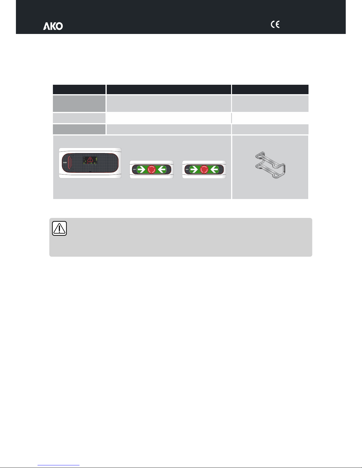
Versions and references......................................................................................................................3
Warnings............................................................................................................................................3
Equipment description ........................................................................................................................4
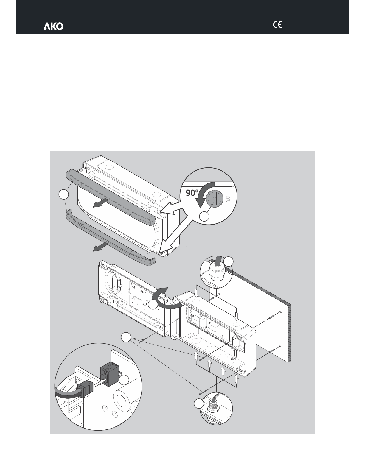
Installation.........................................................................................................................................5
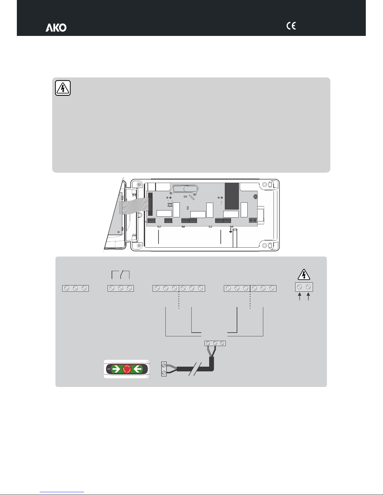
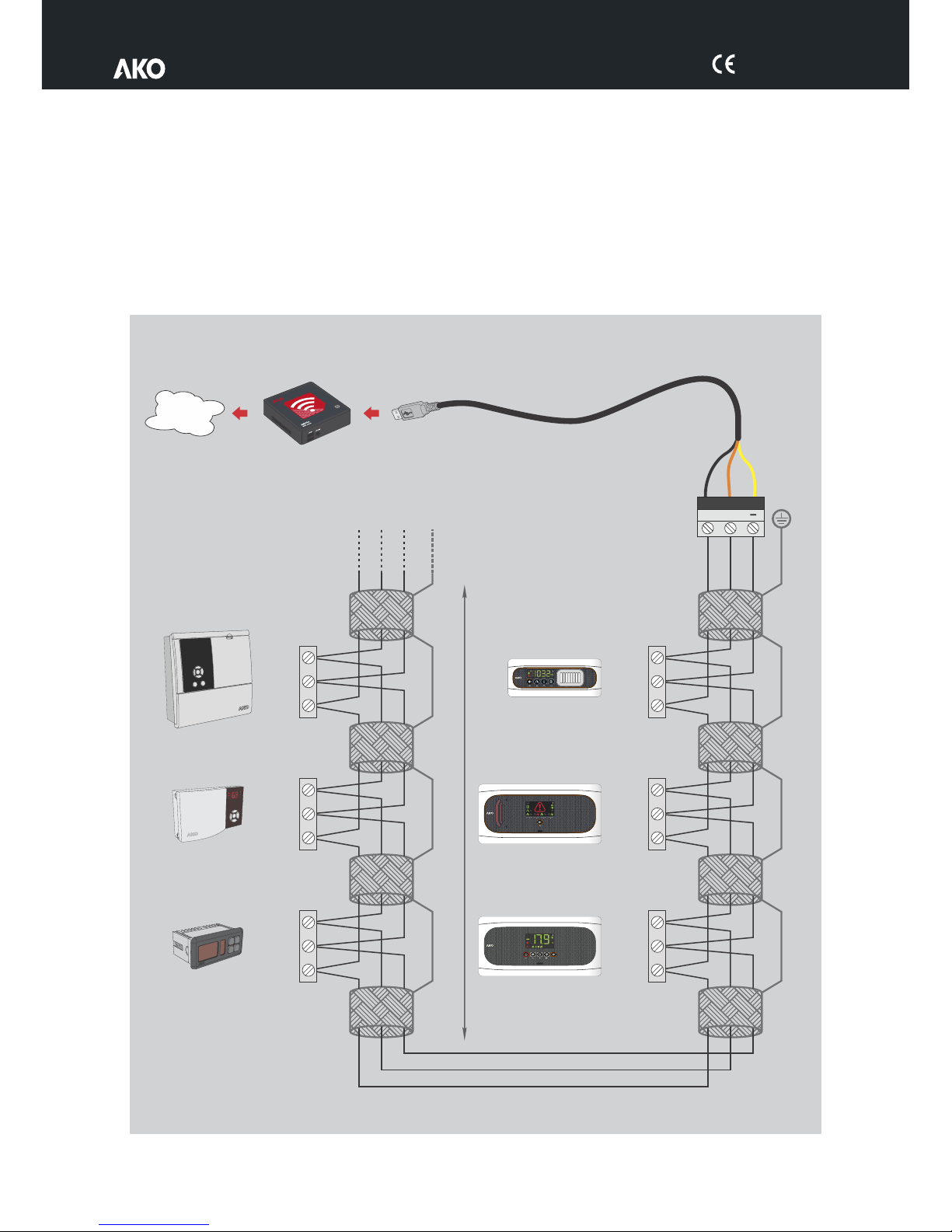
Wiring......................................................................................................................................6
Configuration .....................................................................................................................................7
Operation...........................................................................................................................................8
Maintenance ......................................................................................................................................8
Connectivity .......................................................................................................................................9
Technical specifications.....................................................................................................................10
Accessories ......................................................................................................................................11
5542H402 Ed.03

3
1.- Versions and references
2.- Warnings
-The alarm and push-buttons should be installed in a place protected from vibrations, water and
corrosive gases, where the ambient temperature does not exceed the value indicated in the technical
data. The station should be located in a monitored area, where it is guaranteed that people able to
alert to the presence of alarms will be present.
-Neither the alarm nor the push-button are suitable for areas classified as potentially explosive.
MODEL
DESCRIPTION
POWER SUPPLY
AKO-55424
Station alarm for 4 chambers
100-240 V~
50/60 Hz
AKO-55326
Luminous push-button
-
AKO-58120
Protector for push-button
-
AKO-55424
AKO-55326 AKO-55326
ALARM
AKO-58120
5542H402 Ed.03

5542H402 Ed.03
4
3.- Equipment description
ALARM
Power supply present
Constant green: Battery connected
Switched off: Battery disconnected
Input
1Input
2Input
3Input
4
Constant green: Trapped person push-button connected.
Quick-flashing red: Malfunction / wiring fault in push-button.
Slow-flashing red: Push-button not detected or disconnected.
Constant red: Trapped person alarm activated.
Constant: Alarm activated
Flashing: Malfunction / wiring fault in trapped person push-button.
Indicators
AUTO-CONFIGURATION
push-button
(See page 7)
Visual alarm
Alarm display
Audible alarm

5542H402 Ed.03
5
4.- Installation
- Remove the bezels (1) from the device.
- Loosen the screws (2) with a 1/4 turn and open the cover (3).
- Drill the holes needed for the cable entry glands using the pre-stamped centres on the sides of the housing for
guidance. Fix the glands onto the device (4 and 5).
- Make 3 holes in the wall with the aid of the template included.
- Fix the device to the wall using the screws and plugs supplied (6).
- Insert the cables into the glands and wire the device following the diagram on page 6.
- Connect the battery (7) before closing the cover.
- Close the cover (3), insert and tighten the screws (2) and replace the bezels (1).
7
1
2
3
6
4Ø Max. 25 mm
5Ø Max. 20 mm

5542H402 Ed.03
6
15V
In
Gnd
Input x
15V
Out
Wiring
The wiring between the push-button and the station must NEVER be installed in a conduit alongside power,
control or supply cables.
Always disconnect the power supply to carry out wiring.
For disconnection, the power supply circuit must be equipped with a switch of at least 2 A, 230 V, located near
the device. The power supply cable will be H05VV-F or NYM 1x16/3. The section to be used will depend on
2
current local regulations, but should never be less than 1.5 mm .
Cables for wiring the relay contact should have the relevant section for the device to be connected.
The 120 / 230 V~ wiring area must be kept clear of any other external element
Ensure that you have connected the batteries before starting up the device.
Certain international standards indicate that alarm power supply should originate from a different circuit to
that used for the refrigeration and ventilation system. Be sure to comply with current local regulations.
Tr-
C
Tr+
1
Gnd
2
Trapped
person
RS485 RY1
15V
15V
In
In
Gnd
Gnd
Input 1 Input 2
15V
15V
In
In
Gnd
Gnd
Input 3 Input 4 Vac
100 - 240 V~
50/60 Hz

5542H402 Ed.03
7
5.- Configuration
Input auto-detection
Step 1
When receiving a power supply for the first time, the alarm enters
INPUT AUTO-DETECTION MODE, lighting up the input indicators
sequentially in green.
Step 2
Begin AUTO-DETECTION by pushing the ‘AUTOCONFIG’ push-button
for 5 seconds (See page 4). At the end of the process, the alarm will
emit 5 short beeps and will begin to function normally.
For correct input detection, all devices must be correctly
connected and in NO ALARM mode.
Once the alarm has been configured, this function will not
be activated again. To activate it again, disconnect the
power supply, connect it again and press the
“AUTOCONFIG” pushbutton 5 times consecutively within 2
minutes and repeat step 2 within another 2 minutes.
Self-diagnosis function
The device incorporates a self-diagnosis system which informs the user in the event of a push-button malfunction
or if there are wiring errors.
If a malfunction is detected, the alarm will emit 3 short beeps every 2 minutes and the corresponding input
indicator will flash red.
MODBUS parameter reset
To revert MODBUS parameters to factory settings, activate the INPUT AUTO-DETECTION function and press the
‘AUTOCONFIG’ push-button 5 consecutive times.
MODBUS parameters can only be modified using AKONET software.
ON
OFF
1
2

5542H402 Ed.03
8
6.- Operation
No alarms
The input indicators are green.
Alarm activated
The station emits an audible alarm sound, shows the affected input(s) in red, the general alarm indicator illuminates
and the visual alarm flashes.
Wiring error / malfunction
The station emits 3 short beeps every two minutes and the input indicator affected flashes red.
* The input indicator corresponding to the activated button will turn on.
7.- Maintenance
ŸClean the device surface with a soft cloth, water and soap
ŸDo not use abrasive detergents, petrol, alcohol or solvents, as this could damage the sensor.
ALARM STATION
STATUS
Relays Trappeed
person
With power supply
Battery connected
OFF
With power supply
Battery disconnected
OFF
No power supply /
With battery
OFF
No power supply /
No battery
OFF
Alarm activated
(Push-button activated)
-
-
Bi-tonal
sound
Detector /
wiring fault
-
-
3 tones every
2 minutes
C1 2
C1 2
C1 2
C1 2
*
*
*
*
*
*
C
1 2
C
1 2
No alarms

5542H402 Ed.03
9
+
RS-485
GND
AKO-80039
Tr-: Yellow
Tr+: Orange
GND: Black
Tr-
Tr-
Tr- Tr-
Tr-
Tr-
Tr+
Tr+
Tr+
Tr+
Tr+ Tr+
GndGnd
GndGnd
GndGnd
*AKO controller with communication
**AKO-80024 Use if connecting more than 25 devices
ESC ?
SET
CAMRegis
AKOGAS
AKOALARM
AKOCORE
AKOControl*
AKOControl*
AKO-80039
AKO-5012
LAN
8.- Connectivity
The transmitters are equipped with a port for connection of RS485 (MODBUS) data, allowing it to remotely
manage data using an AKO-5012 web server.
The MODBUS address is factory-set and is indicated on the rating plate located on the left side of the alarm. This
address must be different for each device within the same network. The address can be modified using AKONET
software. Once modified, the original address indicated on the plate will no longer be valid.
>25 **
1000 m
Terminating resistors are not required.
SECURE
CONTROL
Tr+
Tr+
GND
GND
Tr-
Tr-

5542H402 Ed.03
10
9.- Technical specifications
Power supply ......................................................................................................................100-240 V~ 50/60 Hz
Maximum input power .................................................................................................................................15 W
Accumulators ..................................................................................................................................Ni-MH 1.6 Ah
Lighting + alarm autonomy ............................................................................................................> 10 Hours (*)
No. of inputs.......................................................................................................................................................4
Compatibility of inputs...................................................................................................AKO-55326 push-button
Relays.....................................................................................................................................SP T D 8(2)A 250 V~
Working ambient temperature.........................................................................................................-5 ºC to 50 ºC
Storage ambient temperature ........................................................................................................-30 ºC to 60 ºC
Protection degree .........................................................................................................................................IP 65
Installation category ....................................................................................................................II s/ EN 61010-1
Pollution degree ..........................................................................................................................II s/ EN 61010-1
Double isolation between power supply, secondary circuit and relay output.
Sound power..........................................................................................................................90 dB(A) at 1 metre
MODBUS address..........................................................................................................................Shown on label
Maximum push-button cable distance.........................................................................................................300 m
Dimensions...........................................................................................290 mm (W) x 141 mm (H) x 84.4 mm (D)
*Duration in alarm status at an ambient temperature of between 25 ºC.

5542H402 Ed.03
11
10.- Accessories
Protector AKO-58120
Protects AKO-55326 push-button from possible impact.

12
355542402 REV.02 2018
AKO ELECTROMECÁNICA , S.A.L.
Avda. Roquetes, 30-38
08812 Sant Pere de Ribes.•
Barcelona Spain.•
Tel.: +34 902 333 145
Fax: +34 938 934 054
www.ako.com
We reserve the right to supply materials that might vary slightly to those described in our Technical Sheets. Updated information is available on our website.
Table of contents
Other AKO Security System manuals