Alamarin Jet AJ 285 User manual

Installation Manual


Table of contents
Installation Manual
AM/285/EN/1.0.0 iii
Table of contents
1. Introduction .................................................................................................. 1
1.1. Safety precautions ............................................................................. 1
1.2. Symbols ............................................................................................. 1
2. General description of installation ............................................................... 3
3. Installation Methods .................................................................................... 5
3.1. Repowering installation ..................................................................... 7
3.1.1. Reinforced plastic mounting template .................................... 7
3.1.2. Aluminium mounting template .............................................. 12
3.2. Installation out of the mould ........................................................... 12
3.2.1. Removable mounting template mould ................................... 13
3.2.2. Fixed mounting template ...................................................... 14
4. Attaching the propulsion unit .................................................................... 17
4.1. Preparations .................................................................................... 17
4.2. Attaching the body .......................................................................... 18
4.3. Installing the lubrication system for the bearing ............................ 22
4.3.1. Front bearing ........................................................................ 22
4.3.2. Rear bearing ......................................................................... 23
4.4. Attaching the hydraulic cylinders .................................................... 27
4.4.1. Filling the hydraulic cylinder installation holes with
grease .............................................................................................. 29
4.5. Attaching the hydraulic pump ......................................................... 30
4.6. Oil cooling ....................................................................................... 32
4.7. Attaching the grass rake ................................................................. 33
4.8. Installing the raw water cooling line .............................................. 33
4.9. Installing the inspection hatch elevation collar ............................... 35
5. Installing the control system ..................................................................... 37
5.1. Connecting the reversing deflector to the control system ............... 37
5.1.1. Connecting the control cables .............................................. 40
5.1.2. Cylinder adjustment .............................................................. 42
5.2. Connecting the steering nozzle to the control system ..................... 44
6. Engine installation ..................................................................................... 47
7. Antifouling .................................................................................................. 49
Appendix 1. Grease recommendations ........................................................... 51
Appendix 2. Oil recommendations ................................................................. 52
Appendix 3. Tightening torques ..................................................................... 53
Appendix 4. Control system hydraulic line .................................................... 54
Appendix 5. Movement range of the hydraulic cylinder control lever ........... 57
Appendix 6. Fastening screws AJ 285 ............................................................ 58


Introduction
Installation Manual
AM/285/EN/1.0.0 1
1. Introduction
This is the installation manual for Alamarin-Jet's AJ 285 water jet propulsion
unit. This manual is intended for mechanics who install the Alamarin-Jet water
jet propulsion unit to a suitable boat.
© Alamarin-Jet Oy
Tuomisentie 16
FI-62300 Härmä, Finland
Telephone: +358 10 7745 260
Fax: +358 10 7745 269
Internet: www.alamarinjet.com
All rights reserved.
The information in this manual may not be copied, published or reproduced in
any way whatsoever, or exploited for commercial purposes, without express
written permission from Alamarin-Jet Oy.
The information in this manual is subject to change without notice. Alamarin-
Jet Oy reserves the right to modify the contents without notice.
1.1.Safety precautions
Read these instructions carefully before carrying out any procedures. Always
follow these instructions and the safety precautions shown below.
• Only a person with adequate training is allowed to carry out the procedures
described in this manual.
• The person carrying out the procedures must always wear the appropriate
protective equipment.
• The work premises must be sufficiently large, safe and well-lit.
• The tools that are to be used must be clean and appropriate for the intended
purpose.
1.2.Symbols
Please refer to table 1 for a description of the symbols used in this manual.
Table 1. The symbols used in the manual
Icon Description
DANGER
Negligence in the performance of a procedure can cause a threat
to your life.
WARNING
Negligence in the performance of the procedures can lead to
personal injury, breakdown of equipment, or serious malfunction
of the equipment.
CAUTION
The procedure involves minor danger or a possibility of minor
damage to equipment.

Introduction
Installation Manual
2 AM/285/EN/1.0.0
Icon Description
WARRANTY
The warranty is voided if the procedure is carried out incorrectly.
NOTE
Important notice or fact.
TIP
Additional information that facilitates the performance of work or
a procedure.
CARRIED OUT BY ONE PERSON
One person can carry out the procedure.
CARRIED OUT BY TWO PERSONS
Two persons must carry out the procedure.
INDICATOR ARROW
ARROW DESCRIBING MOTION
Please note that this instruction uses the terms "jet" and "jet propulsion unit".
They mainly refer to the same thing.

General description of installation
Installation Manual
AM/285/EN/1.0.0 3
2. General description of installation
Alamarin-Jet water jet propulsion units can be installed on a reinforced plastic,
aluminium, steel, polyethylene, or wooden boat.
Perform the installation in the following order:
1. Attach the mounting template to the boat's hull (section 3. Installation
Methods, page 5).
2. Attach the propulsion unit to the mounting template (section 4. Attaching
the propulsion unit, page 17).
3. Install the control system (section 5. Installing the control system, page
37).
4. Install the engine (section 6. Engine installation, page 47).
5. Paint the propulsion unit with antifouling paint (section 7. Antifouling, page
49).
This is only necessary if the boat is used in waterways where organisms
are likely to attach themselves to the propulsion unit.

General description of installation
Installation Manual
4 AM/285/EN/1.0.0
Installation Methods
Installation Manual
AM/285/EN/1.0.0 5
3. Installation Methods
The Alamarin-Jet water jet propulsion unit is installed on the boat using a
mounting template. Several mounting templates are available, depending on
the installation methods and materials used.
For combi-frames, there are two primary installation methods available:
a) ”short tail”, which minimises the installation length outside the stern
b) ”long tail”, which minimises the installation length inside the stern
Both methods have their advantages, and it is up to the boat designer to
decide which method is best suited for each boat.
Short tail installation
This installation method minimises the installation length of the jet outside
the boat. At the same time, the jet's inspection hatch ends up inside the boat,
which makes it safer to clean the intake duct in rough seas.
Figure1.Short tail installation
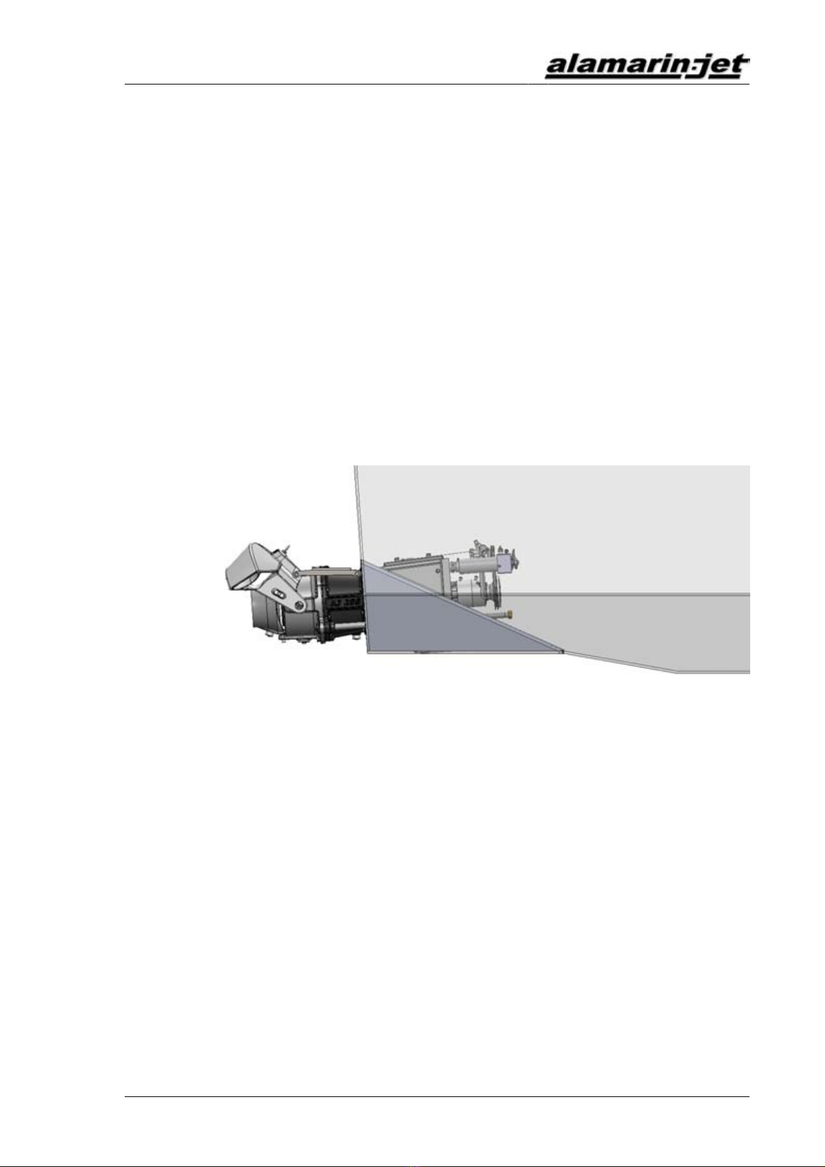
Long tail installation
This installation method minimises the installation length of the jet inside the
boat so the engine can be installed closer to the stern of the boat. The jet's
inspection hatch ends up outside the boat, which reduces the risk of sinking
due to a water leak.

Installation Methods
Installation Manual
6 AM/285/EN/1.0.0
Figure2.Long tail installation
The mounting template can be installed into a hole at the bottom and the stern
of the boat, or the shape of the mounting template can be added to the boat's
template (GRP boats).
The correct positioning of the mounting template is crucial since it determines
the position of the jet. In the example shaft in figure 3 shows the edge parallel
to the keel. When the edge is correctly aligned parallel to the keel, the jet
pushes the boat forward with the optimal thrust angle (4 degrees). The main
shaft of the propulsion unit then slants 4º downwards by reference to the keel.
If the design of the boat requires a different thrust angle, the matter must be
handled and arranged with Alamarin-Jet Oy.
Figure3.Thrust angle

Installation Methods
Installation Manual
AM/285/EN/1.0.0 7
Figure4.Aluminium mounting templates
3.1.Repowering installation
The repowering installation method is used in the propulsion system's
modification installation. In addition, it is an appropriate installation method
for prototype or one-off boats. In aluminium boats, the propulsion unit is
always installed using the repowering principle.
For attaching the mounting template, a hole of an appropriate size is cut in
the stern and the bottom of the boat, in which the mounting template is either
laminated or welded.
3.1.1.Reinforced plastic mounting template
If the installation is done on a boat that has previously had some other type
of rear propulsion unit, make sure that the engine's installation supports
do not impede laminating. There must be at least 150 mm free hull surface
on all sides of the mounting template, on which the mounting template can
be laminated (figure 5). The same 150 mm requirement applies to all boats,
including new ones.
Figure5.Repowering installation

Installation Methods
Installation Manual
8 AM/285/EN/1.0.0
Hull and stern laminate must be dry and clean before work can be
commenced.
Cutting and attaching the mounting template:
1. Make a hole at the bottom and the stern of the boat for the mounting
template. The mounting template should be positioned slightly over
the stern of the boat. The excess part can be cut away after installation
(figures 6 and 7, point A).
The gap between the mounting template and the hull should be fitted so
that it is as small as possible.
2. The front of the mounting template is fitted to a v-bottom boat with the use
of a triangular plate having a length of approximately 600 mm from the
keel.
Figure6.Positioning of the mounting template, "short tail"
Figure7.Positioning of the mounting template, "long tail"
A Collar to be cut off

Installation Methods
Installation Manual
AM/285/EN/1.0.0 9
B V-bottom adaptor plate
Figure8.V-bottom adaptor plate
3. Chamfer the edges of the hole on the bottom and stern of the boat.
The chamfered part must be 150 mm wide and the hole edge thickness
must be 3 mm.
If the boat's hull is made of sandwich laminate, first remove 100 mm of
core material round the hole and then chamfer the core material as well as
about 100 mm of the exterior surface. Slightly chamfer the inner envelope.
4. Fit the mounting template in place and support it from the outside.
NOTE!
The lower surface of the mounting template must be level
with the bottom of the boat (figure 9).
The edge of the mounting template must be parallel with
the boat's keel (= the edge of the hole).
If this is not the case, the propulsion unit thrusts the boat
in the wrong angle and performance is lowered.

Installation Methods
Installation Manual
10 AM/285/EN/1.0.0
Figure9.Cross-section of the mounting template
Figure10.Mounting template alignment
A The edge of the mounting template parallel to the keel
5. Close the seam with tape from the outside.
6. Run gelcoat paint onto the seam from above until it is filled.
7. Laminate 100 mm-wide carpet strips on the seam.
8. Continue laminating over the whole mounting template and the chamfers
until the final thickness of 15 mm is reached.
Installation Methods
Installation Manual
AM/285/EN/1.0.0 11
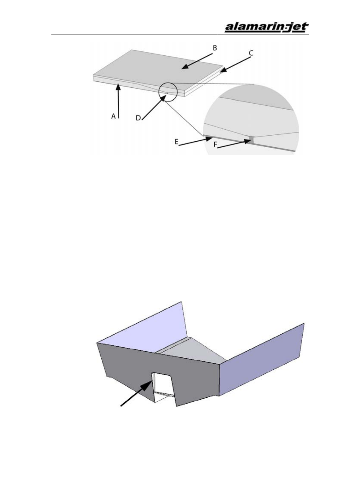
Figure11.Laminating
A Boat hull laminate
B Attachment laminate
C Mounting template laminate
D Seam
E Original gelcoat
F Seam-filling gelcoat
9. Fit engine supports and possible bracings.
10. Cut off the excess collar on the mounting template outside the stern
(figure 12).
Figure12.Excess collar

Installation Methods
Installation Manual
12 AM/285/EN/1.0.0
11. Smooth the seams and paint the visible reinforced plastic surfaces with
topcoat paint.
This is important because an uncovered laminate absorbs water.
3.1.2.Aluminium mounting template
1. Cut a hole of appropriate size in the bottom and the stern of the boat.
In a long tail installation, the collar of the mounting template covers
the inner surface of the stern and the excess material must be cut after
installation (figure 13). In a short tail installation, the excess collar is
outside the stern (figure 6)
Figure13.Long tail aluminium mounting template
The gap between the mounting template and the hull should be fitted so
that it is as small as possible.
2. Chamfer the plate edges as required by general welding standards.
3. Fit the mounting template in place.
Support the mounting template during welding so that the width does not
change.
4. Weld the mounting template in place both on the inside and the outside,
and make the seam watertight.
5. Abrade the welded seams so that they are smooth at the bottom area.
Any uneven spots at the bottom must be trimmed by caulking, for example.
6. Paint the mounting template with paint that is suitable for painting
aluminium.
Follow the paint manufacturer's instructions.
The material of the plate section: AlMg3
Welding filler metal: AlMg5
3.2.Installation out of the mould

Installation Methods
Installation Manual
AM/285/EN/1.0.0 13
If you want to produce one type of boat with several varying propulsion unit
options, it is possible to make a mould of the mounting template and fit it
to the standard hull mould (figure 14). This speeds up installation of the
propulsion unit without adding to mould expenses.
The mould for the mounting template is made from a mounting template
provided by Alamarin-Jet Oy. In twin installations, two moulds must be made,
one for each side of the hull.
CAUTION!
Prepare the mounting template to fit exactly in the boat's
mould. This must be done carefully, as inaccuracies (bulges)
are copied to the final boat and result in deterioration of boat
performance.
Figure14.Making a negative of the mounting template
3.2.1.Removable mounting template mould
If you use a removable mounting template mould, you can use the boat's hull
mould in both jet installation and rear propulsion unit installation. There are
three stages in preparing and installing a removable mounting template:
1. Make a negative (mould) of the mounting template.
2. Process the mould to fit the boat mould exactly.
3. Install the negative onto the boat's mould.
Follow these instructions:
Fitting the mounting template onto the stern of the boat requires care. In twin
installations in particular, the angled cutting of the slanted stern requires
precision.

Installation Methods
Installation Manual
14 AM/285/EN/1.0.0
Figure15.Cutting the collar (twin installation)
The edges of the mounting template must be smoothed so that the end product
shows no big notches.
Reinforce the mounting template negative with a wooden frame, plywood
plate or, for example, urethane foam. This way the collar will not bend inwards
during laminating.
Attach the mounting template mould on to the boat's mould using tape, for
example, so that it stays in place during lamination.
TIP!
It is advisable to mark the location of the mounting template
on the boat mould after the first installation. This makes fitting
the mounting template faster and easier the next time.
CAUTION!
Twin installation!
After the boat has been laminated and is ready to be removed
from the mould, the mounting template negatives detach with
the boat. The mounting templates are removed from the boat
for the next installation.
3.2.2.Fixed mounting template
The mounting template can also be fixed to the mould. In this case, the
boat's hull mould can only be used in jet installation. In twin installation, the
boat's mould must be in two pieces in order to make separating the mounting
templates possible. A two-piece mould is not necessarily needed for single
installation.

Installation Methods
Installation Manual
AM/285/EN/1.0.0 15
Twin installation
1. Make two negatives of the mounting template.
2. Fit and install the mounting templates on the boat's mould (section 3.2.1.
Removable mounting template mould, page 13).
3. Laminate the rear end of the boat in the mould and remove it.
4. Remove the mounting templates.
5. Make a separate mould of the rear end.
Single installation
1. Make a negative of the mounting template.
2. Fit and install the mounting template on the boat mould (section 3.2.1.
Removable mounting template mould, page 13).
3. Laminate the hull of the boat in the mould and remove it.
4. Make a new mould of the hull.

Installation Methods
Installation Manual
16 AM/285/EN/1.0.0
Other manuals for AJ 285
2
Table of contents
Popular Boating Equipment manuals by other brands

Taylor Made
Taylor Made Pontoon Quick-Shade Gazebo instructions

superbrightleds
superbrightleds UBL-RGB120 user manual

Mist-er-Comfort
Mist-er-Comfort 2001 Step By Step Installation Guide

Sunstream
Sunstream FL-24020D Operation manual

Taylor Made
Taylor Made 88125 Installation and owner's manual

LaserPerformance
LaserPerformance V15 manual

Velocitek
Velocitek SC-1 Reference manual

Boston Whaler
Boston Whaler 150 Montauk owner's manual

Ultraflex
Ultraflex UC 81 Installation and maintenance manual

Simrad
Simrad TP10 Service manual

Forespar
Forespar Leisure Furl OFFSHORE IN-BOOM FURLING SYSTEM installation manual

Selden
Selden Furlex 404E Supplementary manual


