3.3.7EXTERNALMIC/SPEAKER (#6)
This jack accepts anoptional headset/microphone for totally handsfree
operation.
Pleaserefer totheuser manual orAlbrecht catalogue.
SeealsosectionregardingVOX SELECTION MODE.
3.4 SettingandOperation
3.4.1BASIC CHANNEL SELECTION
Inordertocommunicatewithother PMR units,bothyouandthereceiving party
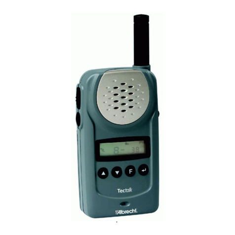
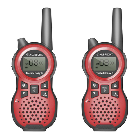
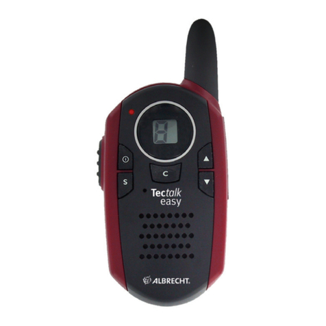
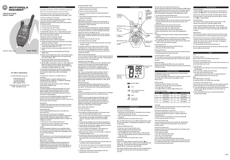
must beonthesamechannel. Tectalk has 8 channels (1-8) asindicated by
thelargedigits intheLCD DisplayPanel (#8).
Before,tryingtotransmit on theselectedchannel, you shouldpress the Monitor
Button(#2) tocheck theactivity onthat channel.
Ifsomeoneis alreadyontheselectedchannel, youshould try another
channel whichis notoccupied.
Tochangethe basicchannel,inthestandbymode,press the
Up Button (#10) briefly tomovetothenexthigher mainchannelnumber.
Press the Down Button (#11) briefly tomovetothe next lower mainchannel
number.
3.4.2CTCSS (Coded ToneControlled SquelchSystem)
SUB-CHANNEL SELECTIONMODE
This featureallowsyoutohavemoreprivacy onthemainchannelbyusingtonecodes
(internationalnumberingsystem00-38)withinamainchannel. This enablesyou to
communicatewithYourpartners on the samemainchannelwhen all partnerstationsuse
the samesubcode.This helpstoavoidcongestion onthe mainchanneland filters out
unwantednoise,static andother stations usingdifferent codes.
Thereare38CTCSS subchannels for eachmain channel.
TochangetheCTCSSsubchannel,
Press theFunctionButton(#12)until thewordcTcappears intheLCD Panel (#8).
Press the UpButton(#10)orthe DownButton (#11)tochoosethe desiredsubchannelto
use.Thecorrespondingsubcodefrequency will be displayedinthelower right corner.
Press theEnterButton(#13) toconfirm your selection.
NOTE:
Tocommunicatewith other PMR units, theymust beswitched to thesame
channel andCTCSSsubcode. Tocommunicate withother LPD units thatdo
nothavesubcodes, switchyour unit tothesamechannel withthesubcode
set toOFF.
3.4.3AUTO CHANNEL SCANMODE
This featureallows youtoscanforan activechannelandcommunicatewiththeparty
transmitting.
