manuals.online logo
Brands
  1. Home
  2. •
  3. Brands
  4. •
  5. Alcad
  6. •
  7. Media Player
  8. •
  9. Alcad ST-100 User manual

Alcad ST-100 User manual

This manual suits for next models

1

Other Alcad Media Player manuals

Alcad 915 Series User manual

Alcad

Alcad 915 Series User manual

Alcad 915 Series User manual

Alcad

Alcad 915 Series User manual

Popular Media Player manuals by other brands

VidaBox LUX installation guide

VidaBox

VidaBox LUX installation guide

CasaTunes CT-3S quick start guide

CasaTunes

CasaTunes CT-3S quick start guide

Yamaha TSX-112 owner's manual

Yamaha

Yamaha TSX-112 owner's manual

Fantec MM-FHDL user manual

Fantec

Fantec MM-FHDL user manual

Visual Land Impulse quick start guide

Visual Land

Visual Land Impulse quick start guide

Philips GoGear Muse SA2MUS08 quick start guide

Philips

Philips GoGear Muse SA2MUS08 quick start guide

Fantec MM-HDRL user manual

Fantec

Fantec MM-HDRL user manual

Kvarta DVB Streamer quick start

Kvarta

Kvarta DVB Streamer quick start

Dune HD Duo 4K user manual

Dune HD

Dune HD Duo 4K user manual

Camos MMS-1000 manual

Camos

Camos MMS-1000 manual

Energy 75 Series user manual

Energy

Energy 75 Series user manual

Z3 Technology DME-03 user guide

Z3 Technology

Z3 Technology DME-03 user guide

Sony SVR-2000 Dimensions

Sony

Sony SVR-2000 Dimensions

Meicheng HD-1080K12 user manual

Meicheng

Meicheng HD-1080K12 user manual

DENAFRIPS ARCE owner's manual

DENAFRIPS

DENAFRIPS ARCE owner's manual

Topaz CMS Media Player Hardware user manual

Topaz

Topaz CMS Media Player Hardware user manual

InFocus LightCast user guide

InFocus

InFocus LightCast user guide

Samsung MP-80S Owner's instructions

Samsung

Samsung MP-80S Owner's instructions

manuals.online logo
manuals.online logoBrands
  • About & Mission
  • Contact us
  • Privacy Policy
  • Terms and Conditions

Copyright 2025 Manuals.Online. All Rights Reserved.

Technote 6: Setting up ST-100 Terrestrial IP Streamers
DVB-T to IP streaming equipment (ST-series) broadcasts multicast streams and TV/radio
channels, selected from a DVB-T multiplex (maximum 8), from digital terrestrial reception, over
a TCP-IP network. TV services broadcast as IPTV streams can be viewed on an individual
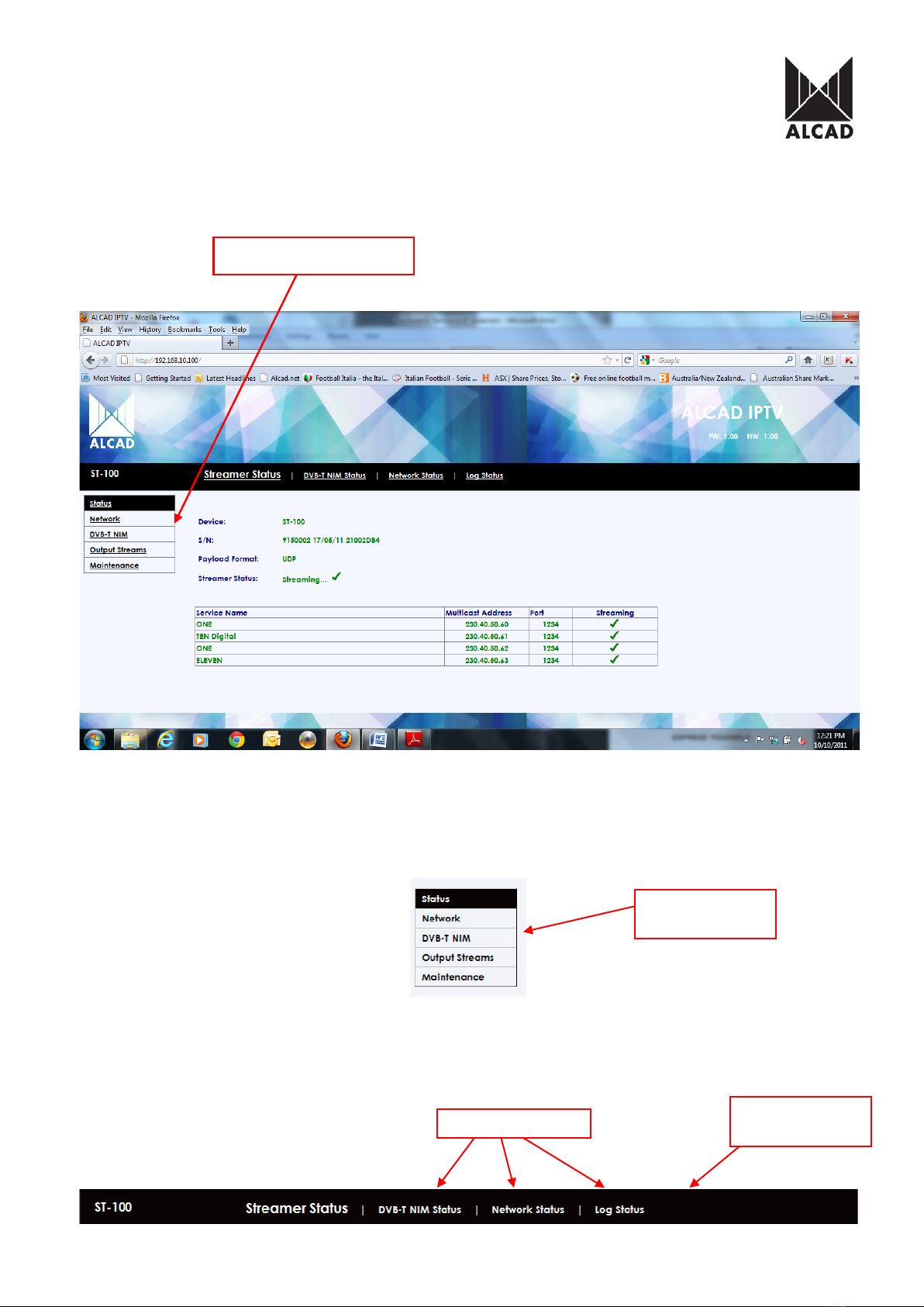
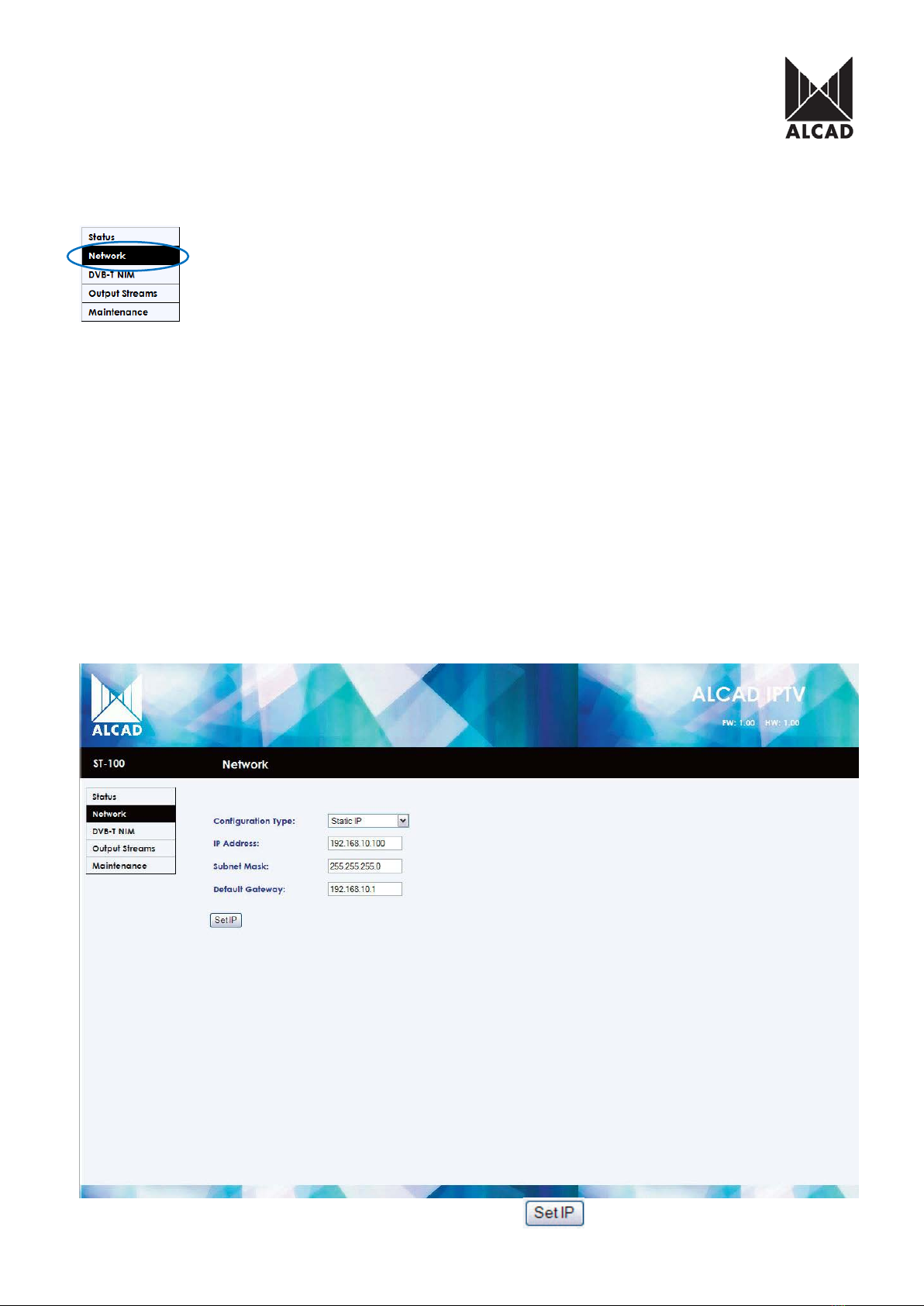
IPTV receiver or by using video reproduction software. The ST modules are configured via
TCP/IP, using either the HTTP protocol (web browser) or TELNET (virtual terminal).
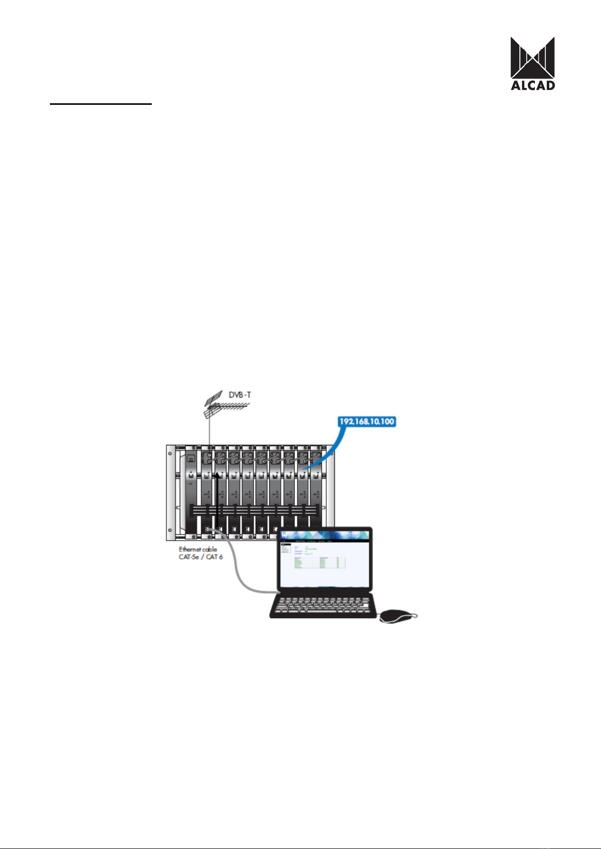
IMPORTANT:It is possible to connect up to 9 ST- 100 modules and 7 ST-110
modules per power supply unit. Each ST module can handle up to 8 MPEG streams; the
IP broadcast, therefore, consists of 8 TV/radio services per module.
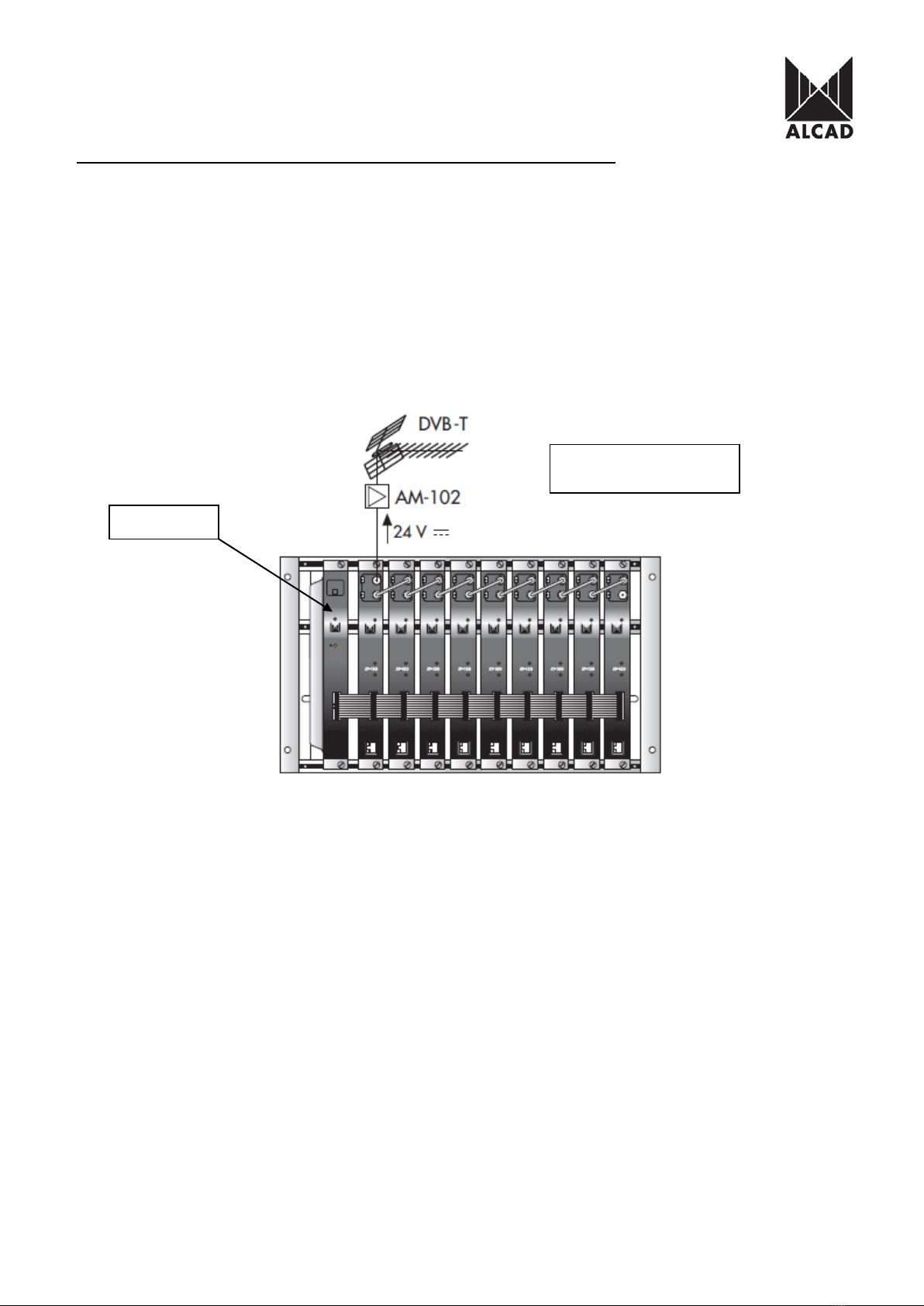
IMPORTANT:Layout of the modules must be as shown above. Power Supply (FA-
310/312) must be located on the far left hand side and Terrestrial IP streamer must be the next
module in the chain. Please look at the above picture.
Ensure the following prior to programming:
•It is necessary to connect all the modules to the support frame SP-226 (code 9120130)
for the system to function.
•It is also recommended that you make the earth connection to the building using a cable
with a section of at least 4 mm.
•Power supply/Control cable must be plugged into each module. DO NOT ADD OR
REMOVE modules without disconnecting mains supply power from wall outlet. Always
disconnect the equipment, and then reconnect it to the mains supply. Failure to do so
can cause equipment to fail.
Power Supply
Automatic power Injection
for masthead amplification
SPECIFICATIONS
Frequency range output of modulators 46MHz --- 862MHz
Operating temperature of Modulators - 10ºC --- +65ºC
Output Level Adjustment 15dB
Input Level 45 - 100dBµV
Streaming Format Multicast UDP, RTP
Supported Protocols IPv4 UDP, RTP, ARP, ICMP, HTTP, TELNET
1.0 PROGRAMMING THE ST MODULE
Once the DVB-T to IP streaming equipment (ST-100/101) has been assembled, each ST
module can be configured. All ST modules use a factory default IP address: 192.168.10.100.
In order to avoid conflicts with other IP addresses, it is necessary to perform an initial
configuration in local mode. Subsequently, it will be possible to access the DVB-T to IP
streaming equipment ST-100 via the local area network (LAN), either to re-programme it or to
check is operating status.
The picture above shows local mode configuration accessing each streamer individually and
assigning new IP addresses. This is strongly advised prior to LAN network connection.
The ST modules have a factory default TCP/IP configuration of:
IP address of the module: 192.168.10.100
Subnet mask: 255.255.255.0
Default Gateway: 192.168.10.1
To access each ST module, use a PC or MAC personal computer equipped with an Ethernet
card and an RJ- 45 cable (CAT-5E or CAT-6).
The IP address of the PC/MAC must be configured within the following range: 192.168.10.2 –
192.168.10.254 (do not use 192.168.10.100, as this is the IP address of the module to be
configured).
2.0 INTRODUCTION TO THE ALCAD IPTV WEB INTERFACE
To start configuring the IP streamers, open the Internet Browser of your preference, and then
type in the address of the streamer which by factory default is set to: http://192.168.10.100
The first page of the ALCAD IPTV graphical user interface will appear on the screen. Access
to the site is protected by username and password. By factory default, the first time the module
is accessed, the username and password is:
User name: alcad
Password: alcad
PLEASE NOTE: Web browser can be Internet Explorer, Mozilla, and Google Chrome
Once you have entered the username and passwords the ALCAD IPTV user interface will be
displayed, which can be seen below.
This is the main navigation menu. Using it, you can switch between the 5 different
configuration menus. The rectangle highlighted in black shows which main menu is active at a
given moment.
The 5 main navigation menus open several configuration screens (Sub-menus) which are
selectable on the configuration bar. To switch between the different configurations screens of
the main menu, click on the tabs of the black configuration bar at the top which can be seen
below
Main Navigation Menu
Main Navigation
Menu
Configuration
Bar (Sub-Menu)
Tabs (Sub-Menu)
DESCRIPTION OF THE ALCAD IPTV Graphical User Interface
The different parts of the ALCAD IPTV Graphical User Interface are shown below:
1 - Click on the ALCAD logo to go to our website: www.alcad.net
2 - ST series model
3 - Version of Firmware (FW) and Hardware (HW) of the module
4 - Main navigation menu
5 - Configuration area
6 - Configuration Bar with tabs
ENG
4
5
1
2
3
6
MAIN NAVIGATION MENU OF THE ALCAD IPTV Graphical User Interface
1.0 Status
This shows information concerning the status and configuration of each block of the ST
module. It is a visual menu only and cannot be modified.
Streamer status
This shows the data of the ST module and a list of the multicast services selected.
Device: model of the ST module.
S/N: serial number of the ST module. Code of the ST module, date of manufacture, and MAC
address (only the last 8 digits).
Payload Format: data format of output streams (UDP, RTP).
Streamer Status: Displays streaming status of the ST module (Streaming, Stopped).
Current
operating
status of the
ST module
(Streaming,
Stopped).
Output stream
format
Serial Number
Model of Device
DVB-T NIM Status
From the Configuration bar the next sub-menu tab is “DVB-T NIM Status”
DVB-T NIM Status
Displays the programmed data of the input tuner of the ST module at a point in time. To see
the BER values at a given instant, press the button on your web browser.
Signal Status: Input signal hook-up indicator.
Channel or Frequency: Input channels (C5–69) or input frequency.
Standard: Standard of the country BG, D/K, I. Australia Select BG ONLY
Offset: Offset of the input signal (Auto, -3/6 –+3/6 MHz).
Bandwidth: Bandwidth of the channel (6, 7 or 8 MHz). Australia Select 7MHz ONLY
BER: quality of the input signal.
Quality of
Input Signal
Bandwidth
Set 7MHz
Tuned to broadcast
carrier
Input Centre Frequency
without OFFSET
OFFSET of
carrier
Network status
From the Configuration bar the next sub-menu tab is “Network Status”
Network Status
Displays the network data programmed on the streamer.
Link: correct connection with the network.
Link Speed: bit speed and Ethernet output.
Configuration Type: fixed or random IP (Static IP, Automatic DHCP).
IP address: IP address of the ST module (Factory-set IP: 192.168.10.100).
Subnet mask: subnet mask
Default Gateway: gateway for access to Internet, predetermined as 192.168.10.1
MAC address: identifying address of each ST module (00:1D:21:XX:XX:XX).
Log status
From the Configuration bar the next sub-menu tab is Log Status”
Log Status
Displays a log of timed events that have occurred within the module. Each event that has
occurred in the ST module has a date and time. If events are marked with an asterisk (*), it
indicates that at the moment at which the event occurred, the date and time displayed were
not synchronised. The list shows the last 10 events to have occurred.
To empty the list of messages, click
The time synchronization of ST-module comes from incoming broadcast carrier.
Logged events can be saved onto a local file, click
CLEAR
event list
SAVE logged
events
2.0 Network
From the “Main Navigation Menu” network settings can be configured from Network tab
The network configuration can either have a fixed IP address (Static IP) or have one which is
automatically assigned by a DHCP server (Automatic DHCP).
Configuration Type: Static IP, Automatic DHCP
IP address: IP address of the ST module (factory-set value of 192.168.10.100).
The range of configurable IP addresses is: 192.168.0.2 – 192.168.255.254
Subnet mask: factory-set value of 255.255.255.0
Configuration range: 0.0.0.0 – 255.255.255.0
Default Gateway: gateway for access to Internet (factory-set value of 192.168.10.1)
The range of configurable IP addresses is: 192.168.0.1 – 192.168.255.254
To save any changes made to Network settings click