Installation instructions 4
P
Pr
re
ep
pl
la
an
nn
ne
ed
d
A
Ac
cc
ce
es
ss
so
or
ry
y
P
Po
os
si
it
ti
io
on
ni
in
ng
g
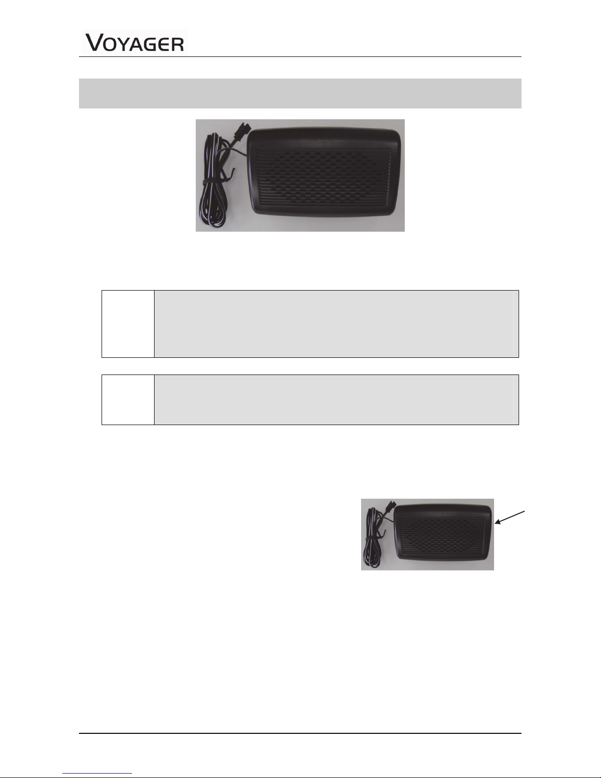
Positioning of all accessories must be planned in advance before installation begins.
Ensure that no wire braids go through locations where Phone accessories are to
be installed.
Ensure that any parts of the handsfree Phone will not interfere with the vehicle
or its accessories’ operation.
P
Pl
la
an
n
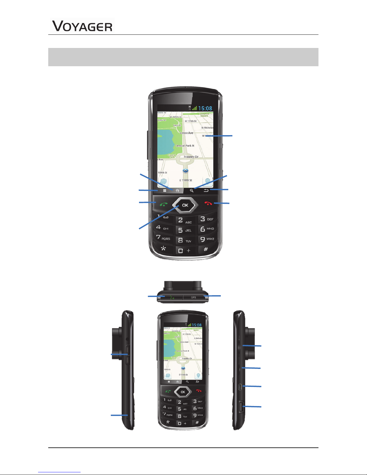
P
Ph
ho
on
ne
e
a
an
nd
d
S
Sw
wi
iv
ve
el
l
m
mo
ou
un
nt
t
P
Po
os
si
it
ti
io
on
ns
s
Note!
The best way to determine the Phone’s position to the customer’s full
satisfaction is to locate it when the customer is beside you and obtain
his/her approval.
Please ensure the Phone’s location does not interfere with the vehicle or its
accessories operation: it should not interfere with opening the glove
compartment or ashtray, should not prevent access to the lighter, moving the
gear stick, operating the hand break etc.
Warning!
Do not install the Phone in front of the vehicle’s air bag. This
restriction must be adhered to, as in the case of an emergency the
air bag blows up and can fail to work properly.
Ensure the surface on which this Phone is installed is sufficiently strong to carry
the weight and pressure which would be exerted on it.
When selecting the Phone’s location, please ensure the control cable connected
to it does not interfere with the vehicle or its accessories’ operation.
Ensure it is safe and convenient to operate the Phone and read the display from
the driver’s seat.
Ensure the Phone would be protected from direct sunlight and humidity (air
conditioner openings).
Ensure the Phone would be protected from mechanical damage by the car’s
accessories.