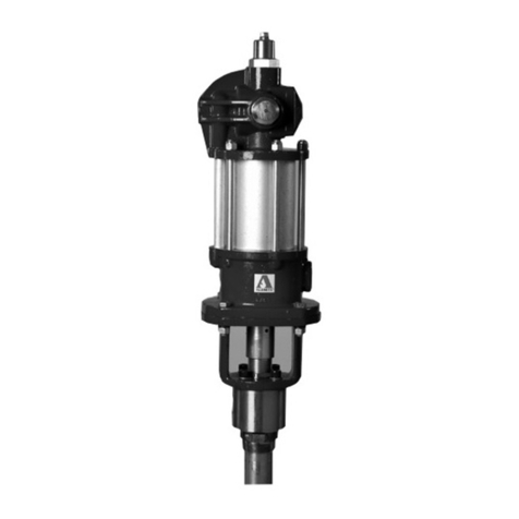
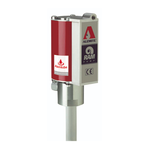
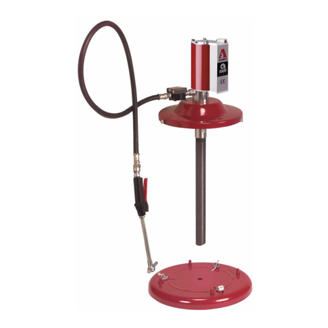
Alemite 7886-A5 Instruction Manual

Model -A
Medium-pressure
material pump
User and maintenance instructions
Date of issue October 2020
Form number 670752
Version 2

Safety . . . . . . . . . . . . . . . . . . . . . . . . . . .
Description. . . . . . . . . . . . . . . . . . . . . . . 4
Air motor specifications . . . . . . . . . . .
Pump tube specifications . . . . . . . . . .
Pump dimensions. . . . . . . . . . . . . . . .
Accessories . . . . . . . . . . . . . . . . . . . . .
Hoists . . . . . . . . . . . . . . . . . . . . . . . . .
Pump performance. . . . . . . . . . . . . . .
Maintenance and repair . . . . . . . . . . . . 7
Overhaul . . . . . . . . . . . . . . . . . . . . . . . . .
Disassembly . . . . . . . . . . . . . . . . . . . .
Installation . . . . . . . . . . . . . . . . . . . . .
Service . . . . . . . . . . . . . . . . . . . . . . . . . . 14
Service hints . . . . . . . . . . . . . . . . . . . . . .
Service parts. . . . . . . . . . . . . . . . . . . . . .
Repair kits . . . . . . . . . . . . . . . . . . . . . .
Troubleshooting . . . . . . . . . . . . . . . . . . 20
Contents

Explanation of signal
words for safety
NOTE
Emphasizes useful hints and
recommendations as well as
information to prevent property damage
and ensure efficient trouble-free
operation.
CAUTION
Indicates a dangerous situation that can
lead to light personal injury if
precautionary measures are ignored.
WARNING
Indicates a dangerous situation that
could lead to death or serious injury if
precautionary measures are ignored.
DANGER
Indicates a dangerous situation that will
lead to death or serious injury if
precautionary measures are ignored.
Safety
• Read and carefully observe these
installation instructions before installing,
operating or troubleshooting pump.
Pump must be installed, maintained and
repaired exclusively by persons familiar
with instructions.
• Install assembly only after safety
instructions and this guide have been read
and are completely understood.
• Review parts list and nomenclature prior
to disassembly or operation.
• Adequate personal protection must be
used to prevent splashing of material on
skin or in eyes.
• Always disconnect power source
(electricity, air or hydraulic) from pump
when it is not being used.
• This equipment generates very high
pressure. Extreme caution should be used
when operating this equipment as
material leaks from loose or ruptured
components can inject fluid through skin
and into body. If any fluid appears to
penetrate skin, seek attention from a
doctor immediately.
• Do not treat injury as a simple cut. Tell
attending doctor exactly what type of fluid
was injected.
• Any other use not in accordance with
instructions will result in loss of claim for
warranty or liability.
• Do not misuse, over-pressurize, modify
parts, use incompatible chemicals, fluids,
or use worn and/or damaged parts.
• Do not exceed stated maximum working
pressure of pump or of lowest rated com-
ponent in system.
• Always read and follow fluid manufactur-
er’s recommendations regarding fluid
compatibility and use of protective cloth-
ing and equipment.
• Failure to comply may result in death or
serious injury.
• Do not operate this equipment without ear
protection. Equipment generates noise at
high decibels. Failure to comply may cause
hearing loss.

Table 1
Air motor specifications
Piston diameter 1/4in (108 mm)
Stroke in (102 mm)
Air inlet 3/4in NPTF (f)
Max air pressure psi (14 bar)
Table 2
Pump tube specifications
Material outlet in NPTF
Max material pressure psi (152 bar)
Max delivery gal/min (53 l/min)
Displacement per cycle . in(157.6 cm3)
Table 3
Accessories
Model Air hose Cover Union Muffler
-A - - ( gal)
- ( gal) )
(/ l)
Table 4
Hoists
Model Description Hoist model Adapter plate Follower plate ) Follower adapter
lb lb
-A Single post - –
-
- –
Dual post -F -- -- )
NOTE
Model can be hoist-mounted
(† Table 4, page 4).
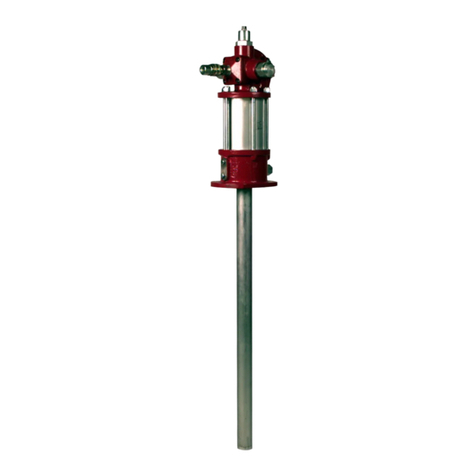
Model series pumps consist of a recip-
rocating air motor and a double-acting
pump tube.
Pump motor does not come in contact
with product being pumped. Motor is pro-
tected from product contamination and
allows motor separation without pump
tube disassembly.
Pump tubes are designed to enable deliv-
ery of a variety of materials.
A bung adapter [( in NPTF (m)] is part of
the pump and allows operation directly from
original drums or bulk containers.
Pump model -A is designed with a
pump tube length to accommodate
gallon or / liter drums.
Description
) Cover contains inspection/fill port.
) Requires adapter (Attaches plate to inlet of pump)
) Included with hoist.

∅ 2 in
(51 mm)
∅ 2 3/16 in
(55 mm)
62 5/8 in
(1 590 mm)
32 1/2 in
(825 mm)
1)
4)
3)
2)
) Air inlet
) Air outlet
) Material inlet
) Material outlet
Fig. 1
Pump dimensions

210
180
150
120
90
60
30
1 750
1 250
1 500
1 000
750
250
500
0
120
100
110
90
80
60
70
50
40
20
30
10
0 2 4 6 8 10 12 14
105 15 20 25 30 35 40 45 50
0
5 500
5 000
4 500
4 000
3 500
3 000
2 500
2 000
1 500
1 000
500
bar psi
Material discharge pressure Air consumption
SAE 10 oil at 75 °F (24 °C)
Delivery
Gallons per minute 4)
Liters per minute 5)
cfm lpm
150 psi (10,3 bar) 1) 3)
100 psi (6,9 bar) 1) 3)
50 psi (3,4 bar) 1) 3)
150 psi (10,3 bar) 1) 2)
100 psi (6,9 bar) 1) 2)
50 psi (3,4 bar) 1) 2)
150 psi (10,3 bar) 1) 3)
100 psi (6,9 bar) 1) 3)
50 psi (3,4 bar) 1) 3)
150 psi (10,3 bar) 1) 2)
100 psi (6,9 bar) 1) 2)
50 psi (3,4 bar) 1) 2)
Pump performance
Pump’s ability to deliver material is based on
pressure (psi/bars) and quantity (cfm/lpm) of
air supplied to motor and amount of material
discharge backpressure to be overcome
within system.
Pump performance (page 6) contains
curves based on three different air pres-
sures. Curves relate delivery in gallons
(liters) per minute (X axis) to air consumption
in cubic feet (liters) per minute (rightY axis)
and to material discharge pressure in
psi/bars (left Y axis).
) Air pressure
) Material discharge pressure
) Air consumption
) pounds approximates gallon
) grams approximates liter
Fig. 2
Pump performance
Delivery versus discharge pressure and air consumption.

Maintenance and repair
Disassembly
Separate air motor from
pump tube
1 Clamp pump assembly vertically in a vise
at bung adapter (21).
2 Remove screws (44), lock washers (46),
and nuts (47) that secure air motor
assembly to pump tube assembly.
3 Lift motor upward to expose upper cou-
pling (1) while placing a wood block onto
surface of upper mounting (8) (†Fig. 3,
page 8).
4 Lower air motor onto wood block.
5 Remove upper spring clip (2) that
secures air motor piston to coupling.
6 Rotate coupling until air motor piston
is free.
7 Remove air motor assembly.
NOTE
Refer to Fig. IPB 1 (page 16) for
component identification on all
overhaul procedures.
WARNING
Prior to performing any maintenance,
safety precautions must be observed.
Failure to comply may lead to per-
sonal injury.
WARNING
Do not use halogenated hydrocarbon
solvents such as methylene chloride or
,,-trichloroethane in this pump. An
explosion can result within an enclosed
device capable of containing pressure
when aluminum and/or zinc plated
parts in pump come in contact with
halogenated hydrocarbon solvents.
Failure to comply may lead to death or
serious personal injury.
WARNING
Release all pressure within system prior
to performing any overhaul procedure.
• Disconnect air supply line from
pump motor.
• Into an appropriate container, operate
control valve to discharge remaining
pressure within system.
Failure to comply may lead to per-
sonal injury.
WARNING
Do not point a control valve at any por-
tion of body or another person. Acciden-
tal discharge of pressure and/or mate-
rial can occur.
Failure to comply may lead to death or
serious personal injury.
WARNING
Read each step of instructions carefully.
Make sure proper understanding is
achieved before proceeding.
Failure to comply may lead to death or
serious personal injury.
Overhaul Access to body packing
8 Remove lower spring clip (2) that secures
rod (3) to coupling.
9 Remove coupling from rod.
10 Remove packing screw (4) from plate (7).
11 Clamp pump assembly horizontally in a
vise (material outlet upward) at
body (11).
12 Unscrew and remove extension cylinder
(23) with attached components, from
body using a strap wrench.
13 Remove o-ring (22) from extension
cylinder.
Body packing
14 Remove screw (19) from body. Access is
through body’s outlet.
15 From bottom of body remove spacer
(20), male rings (17), V-packings (16),
female rings (15), washers (14), and lan-
tern ring (18).

NOTE
Use appropriate Repair kits (page 17)
for replacement parts. Make sure all
components are included in kit before
discarding used parts.
Pump tube
16 Unscrew valve body (39) from
cylinder (35).
17 Remove o-ring (34) from cylinder.
18 Remove stop washer (36), washer (37),
and ball (38) from valve body.
19 Push rod (3) out extension cylinder.
20 Remove rod assembly from cylinder.
21 Remove upper and lower spring clips (2)
that secure extension rod (25) and stem
(26) to lower coupling (1).
22 Unscrew rod assembly and stem assem-
bly from coupling.
23 Clamp flats of stem assembly in a vise.
24 Unscrew valve (33) from stem.
25 Remove body and V-packing assembly
from stem.
26 Remove stop (27) from stem.
27 Unscrew valve seat (32) from guide (28).
28 From top of body remove spring (29),
washer (14), male ring (30), V-packings
(16), and female ring (31).
29 Unscrew coupling (24) from cylinder (35)
using two strap wrenches.
30 Remove additional o-ring (34).
31 Unscrew extension cylinder (23) from
coupling.
32 Remove additional o-ring (22).
Optional procedures
33 Unscrew rod (3) from extension rod (25)
as required.
34 Remove screws (5) and lock washers (6)
that secure plate (7) to body as required.
35 Remove plate from upper mounting (8).
36 Remove hydraulic fitting (9) as required.
37 Unscrew valve seat (12) with screw (13)
as required.
Clean and inspect
1 Clean all metal parts in a modified petro-
leum-based solvent. Solvent should be
environmentally safe.
2 Make sure to remove thread sealant
from both male and female threaded
connections.
3 Inspect all parts for wear and/or damage.
Replace as necessary.
4 Inspect rod (3) and cylinder (35) closely.
Use a magnifying glass to detect any
score marks. Replace as necessary.
5 Closely inspect mating surfaces of all
check valve components for any imper-
fections. Ensure a smooth and clean
contact is obtained when assembled.
For example: Place ball (38) into valve
body (39). Fill valve body with solvent.
Make sure no leakage occurs.
Fig. 3
Separating air motor from pump tube

Assembly 4 Install screw (19) into spacer and body.
Tighten screw securely. Make sure
spacer moves.
5 Position body small diameter upward.
6 Install and align upper mounting (8)
onto body.
7 Install and align plate (7) onto body.
8 Install lock washers (6) and screws (5)
that secure plate and upper mounting to
body. Tighten screws securely in a criss-
cross pattern.
Pump tube
9 Secure extension rod (25) securely in a
soft-jaw vise.
10 Screw rod (3) onto extension rod [with
threadlocker]. Tighten securely.
Piston packing
12 Clamp flats of guide (28) horizontally into
a soft-jaw vise.
13 Install and seat spring (29) onto guide.
14 Position valve seat (32) with small diam-
eter upward.
15 Install and seat the following compo-
nents in order:
NOTE
Prior to assembly, certain components
require lubrication in clean oil. Refer to
Table 5 (page 9) for details.
CAUTION
Use care not to trap spring (29) during
assembly.
CAUTION
Use care installing rod assembly into
body assembly. Damage to V-packings
can occur.
CAUTION
Make sure screw (19) does not bind on
spacer (20). Screw seats on body (11)
and allows spacer (20) to move.
Body packing
Refer to Fig. IPB 1 (page 16) for a section
view of pump tube assembly.
1 Position body (11) large diameter
upward.
2 Install and seat following components
in order:
2.1 Washer (14)
2.2 Female ring (15) with concave sur-
face upward
2.3 Four V-packings (16) with concave
surface upward
2.4 Male ring (17) with flat surface
upward
2.5 Washer (14)
2.6 Lantern ring (18)
2.7 Washer (14)
2.8 Female ring (15) with concave sur-
face upward
2.9 Four V-packings (16) with concave
surface upward
2.10 Male ring (17) with flat surface
upward
3 Install spacer (20) [small diameter first]
into body. Make sure spacer aligns with
bolt hole and seats properly.
11 Install rod assembly [extension rod first]
into top of body assembly.
15.1 Female ring (31) with concave sur-
face upward
15.2 Five V-packings (16) with concave
surface upward
15.3 Male ring (30) with flat surface
upward
15.4 Washer (14)
16 Screw valve seat assembly into guide.
Reposition spring onto body as required.
17 Install stop (27) onto stem (26).
18 Install valve seat and guide assembly
(guide end first) onto stem assembly.
19 Clamp flats of valve (33) horizontally into
a soft-jaw vise.
20 Screw stem assembly [with threadlocker]
into valve. Tighten stem assembly
securely.
21 Tighten valve (33) to stem (26) until it
bottoms out.
22 Screw lower coupling (1) onto stem until
spring clip holes align.
23 Install spring clip (2).
Table 5
Lubricated components
Item Description
V-packing (Buna-N and PTFE)
O-ring, 3/4in ID × 7/8in OD
O-ring, 7/8in ID × in OD

30 Install o-rings (34) onto each end of cyl-
inder (35).
Valve body
32 Install ball (38) into top of valve
body (39).
33 Install and seat washer (37) and stop
washer (36) [convex upward] into
valve body.
34 Screw valve body assembly onto cylinder
(with threadlocker). Make sure ball
moves freely.
35 Place a large wrench or other suitable
tool into slot of valve body. Tighten all
components of assembly securely.
36 Install tag (10) and hydraulic fitting (9)
as required.
37 Screw valve seat (12) [with screw (13)]
into body as required. Make sure bleed
hole points downward.
NOTE
If a primer is used with threadlocker,
curing time is reduced.
NOTE
Make sure o-ring (34) fits in groove at
shoulder of cylinder (35) (†Fig. 5,
page 15).
NOTE
Do not tighten at this time.
NOTE
Do not tighten at this time.
NOTE
Do not tighten at this time.
NOTE
Make sure o-ring (22) fits in groove at
shoulder of extension cylinder (23)
(†Fig. 5, page 15).
CAUTION
Use care installing cylinder (35) into
coupling (24). Damage to V-packings
(16) can occur.
Rods and cylinders
24 Install o-rings (22) onto each end of
extension cylinder (23).
Valve seat and guide assembly
28 Install valve seat and guide assembly
onto extension rod (25) until spring clip
holes align.
29 Install spring clip (2).
31 Screw cylinder (knurled end first) [with
threadlocker] into coupling.
25 Screw extension cylinder (knurled end
first) [with threadlocker] into body
assembly.
26 Install bung adapter (21) onto extension
cylinder.
27 Screw coupling (24) onto extension cyl-
inder (with threadlocker).

Attach air motor to pump
tube
1 Extend rod (3) from top of body assembly
until it locks.
7 Place a wood block onto surface of upper
mounting (†Fig. 3, page 8).
8 Position air motor assembly (41) onto
pump tube assembly and block. Make
sure to orient air motor assembly
properly.
9 Screw air motor piston rod onto coupling
until spring clip holes align.
10 Install spring clip.
11 Remove block and position air motor
assembly onto pump tube assembly.
12 Install screws (44), lock washers (46),
and nuts (47) that secure air motor
assembly to pump tube assembly.
Tighten screws securely in a criss-cross
pattern.
Lubricate V-packings
13 Open valve screw (13).
14 Place an appropriate collection container
underneath valve seat.
15 Attach a grease gun to hydraulic fitting
(9).
16 Pump a high quality NLGI or grease
until grease is free of air.
17 Close valve screw.
NOTE
Do not overtighten screw (4). Pump
must cycle with an initial air pressure
setting of psi (1 bar).
NOTE
If PTFE V-packings are used, fill screw
cavity with a solution that prevents
product from drying on rod.
NOTE
Refill cavity at each pump changeover.
Note that oil may overflow opening of
packing screw (4) on initial start-up.
This is due to position of rod (3) [not at
top dead center].
NOTE
Lubricate V-packings (16) once again
after hours of operation. Thereafter,
lubricate once every hours of
operation.
NOTE
This step is important for visual feed-
back due to possible leakage during ini-
tial start up procedures.
2 Tighten packing screw (4) into plate (7)
until it contacts V-packing group. Use
torque bar to snug installation.
3 Screw upper coupling (1) onto rod until
spring clip holes align.
4 Install spring clip (2).
5 Position pump assembly vertically in a
soft-jaw vise.
6 Fill cavity of packing screw with oil.

Bench test and
operation
NOTE
Pump must begin to cycle once air pres-
sure reaches psi (1 bar).
NOTE
Use the following procedures for pumps
with PTFE V-packings.
1 Open control valve and allow pump to
operate for minutes.
2 Inspect packing screw (4) for leakage.
Should oil (solution) overflow torque
hole in packing screw, tighten packing
screw clockwise an additional 1/8turn.
NOTE
After - hours of operation, inspect
packing screw for leakage once again.
Tighten an additional 1/8turn as
required.
NOTE
Pump may not cycle for additional rea-
sons. Refer to Troubleshooting (page 20)
for details.
5 Continue to adjust packing screw until
pump begins to cycle at psi (1 bar).
With air pressure at zero:
6 Connect a product hose to pump’s mate-
rial outlet. Direct hose into a collection
container.
7 Place pump in product to be dispensed.
8 Slowly supply air pressure to pump’s
motor once again.
9 Allow pump to cycle slowly until product
is free of air.
If pump assembly does not prime, refer to
Troubleshooting (page 20) for details.
10 Inspect packing screw (4) for leakage.
Should oil (solution) overflow torque hole
in packing screw, tighten packing screw
clockwise 1/8turn.
With air pressure at zero:
11 Attach a control valve to outlet hose of
pump. Make sure nozzle on control valve
is open and pointed into an appropriate
collection container.
12 Slowly supply air pressure to pump’s
motor.
13 Allow pump to cycle slowly until product
is once again free of air.
14 Set air pressure to psi (7 bar).
15 Operate control valve into container
momentarily.
16 Shut off control valve.
Visually inspect pump for external leaks.
Pump should not cycle more than once
or twice in one hour. If pump does not
stall, refer to Troubleshooting (page 20)
for details.
17 Check motor for air leakage. If motor
leaks, refer to 397871 for details.
WARNING
Do not exceed lowest pressure rating of
any component in system.
Never point a control valve at any
portion of your body or another person.
Lubricant discharged at high velocity
can penetrate skin and cause severe
injury. Should any fluid appear to punc-
ture skin, get medical care immediately.
Ensure all components are in opera-
ble condition. Replace any suspect parts
prior to operation.
Should leakage occur anywhere
within system, disconnect air to motor.
Personal injury can occur.
Initial start up
1 Make sure air pressure at regulator
reads zero.
2 Install air connector (42) to inlet of
air motor.
3 Connect air coupler (43) to connector.
CAUTION
Do not operate pump longer than
minutes during adjustment procedure.
Excessive heat due to friction can
change setting.
4 Slowly supply air pressure [not to exceed
psi (1 bar)] to pump’s motor. Pump
assembly should begin to cycle. If pump
assembly does not cycle, loosen
packing screw. Should pump cycle before
psi (1 bar) is reached, tighten packing
screw.

45
46
40
47
41
42
43
44
Installation
Additional items that should be incorporated
into air piping systems are listed in
Air line components (page 13).
Table 6
Air line components
Part Description
Moisture separator/regulator and gauge combination
- Moisture separator
-B Regulator and gauge
- Lubricator )
) Air motor is lubricated at factory, life of motor can be extended
with use of a lubricator.
Fig. 4
Pump housing

Service
Service hints
Settings effect efficiency of pump. Refer to
Overhaul (page 7) for details.
A Observe hole in packing screw (4) for oil
overflow. See Troubleshooting (page 20)
for corrective measures.
B Fill cavity of packing screw (4) with oil to
prevent product from drying on rod (25).
C Loosen valve screw (13) prior to seal lubri-
cation. Damage to seals can occur.

1
4
13
27
26
33
23
22
34
35
A
B
C
Fig. 5
Service hints

3
4
7
8
11
21
20
17
16
15
14
18
14
17
16
15
14
22
23
22
24
25
2
1
2
26*
27
28
29
39
38
37
36
34
35
34
33*
32
31
16
30
14
B
A
A
A
A
A
A
C
D
5
6
9
10
12
13
19
21
2
A) Apply threadlocker
B) Torque bar
C) Point bleed hole downward
D) Apply thread sealant
* Indicates change.
Fig. IPB 1

) Part numbers not available separately.
Service parts
Item Description Part Quantity Item Description Part Quantity
Coupling Extension rod
Clip Stem
Rod Stop
Packing screw Guide
Screw, 1/2in- × 3/4in Spring
Lockwasher, 1/2in Ring, male
Plate Ring, female
Upper mounting Valve seat
Hydraulic fitting -B Valve
Tag O-ring, 7/8in ID × in OD
Body Cylinder
Release valve seat, 1/8in NPTF(m) Stop washer
Valve screw, 1/4in - × . in Washer
Washer, . in Ball
Ring, female (brass) Inlet valve body
V-packing (Buna-N) - Eyebolt, 3/8in NPTF(m)
Ring, male (brass) Air motor assembly
Ring, lantern Connector, 3/4in NPTF(m)
Screw, 1/4in - × 3/8in Air coupler, 1/2in NPTF(f)
Spacer Screw, 1/2in - × in
Bung adapter, in NPTF(m) -B Pump tube assembly
O-ring, 3/4in ID × 7/8in OD Lockwasher, 1/2in
Extension cylinder - Nut, 1/2in -
Coupling
Repair kits
Kit number 393004
Item Description Part Quantity
Clip
Washer, . in
V-packing (Buna-N) -
Ring, male
Ring, female
O-ring, 7/8in ID × in OD
Kit number 393005
Item Description Part Quantity
Clip
Washer, . in
Ring, female (brass)
V-packing (Buna-N)
O-ring, 3/4in ID × 7/8in OD
O-ring, 7/8in ID × in OD -

22
22
27
26
29
39
38
34
34
33
32
31
16
30
14
16
15
14
14
16
15
14
19
2
Repair kit 393003
Item Description Part Quantity Item Description Part Quantity
Clip Ring, male
Washer, . in Ring, female
Ring, female (brass) ) Valve seat
V-packing (Buna-N) - Valve
Screw, 1/4in - × 3/8in O-ring, 7/8in ID × in OD -
O-ring, -3/4in ID × 7/8in OD - Ball -
Stem Inlet valve body
Stop
Spring
Fig. 6
Repair kit 393003

62 5/8 in
1)
2)
Repair kit 331916
Item Description Part Quantity Item Description Part Quantity
Clip O-ring, 3/4in ID × 7/8in OD -
Washer, . in Ring, female
Ring, female (brass) O-ring, 7/8in ID × in OD -
V-packing (PTFE) -
Fig. 7
Repair kit 331916

Troubleshooting
Condition Possible cause Corrective action
Pump does not cycle Packing screw (4) too tight Loosen packing screw (4)
Air motor not operating properly Inspect air motor and rebuild or replace
as necessary
Pump tube jammed and/or contains loose
components
Rebuild pump tube
Insufficient air pressure Increase air pressure
Pump will not prime Excessive cycling speed Reduce air pressure
Pump leaking internally See internal leaks
Pump cycles rapidly Product source empty Replenish product
Pump cycles continuously, or slowly
(once or twice/hour)
Pump leaking internally See internal leaks
Pump leaking externally See external leaks
Distribution system leaking Correct leak
External leaks
Product leakage visible at top or bottom of
packing screw (4)
Packing screw (4) not sufficiently tight Tighten packing screw (4) with torque bar
Worn or damaged V-packings (16)Replace V-packings (16)
Damaged rod (3) Inspect rod (3) and replace as necessary
Product leakage visible at bottom of body (11) Pump tube not sufficiently tight Tighten pump tube assembly
Damaged o-ring (22) Replace o-ring (22)
Product leakage visible at top and/or bottom of
coupling (24)
Cylinder(s) not sufficiently tight Tighten extension cylinder (23) and/or cylinder
(35) into coupling (24)
Damaged o-ring (22) and/or (34) Replace o-ring (22) and/or (34)
Product leakage visible at top of valve body (39)
Valve body (39) not sufficiently tight Tighten valve body (39) into cylinder (35)
Damaged o-ring (34) Replace o-ring (34)
Internal leaks
Pump does not prime or cycles continuously,
or slowly (once or twice/hour)
Foreign material between ball (38) and
valve body (39)
Locate and eliminate source of foreign material
Foreign material between valve (34) and
valve seat (32)
Locate and eliminate source of foreign material
Worn or damaged component(s): Disassemble pump tube, clean, inspect and
replace worn or damaged components• Ball (38)
• Valve body (39)
• Valve (33)
• Valve seat (32)
• V-packings (16)
• Rod (3)
• Cylinder (35)
• Spring (29)
Table of contents
Other Alemite Water Pump manuals

Alemite
Alemite 8702 Series User manual

Alemite
Alemite 9911-H1 User manual

Alemite
Alemite 8595-C User manual

Alemite
Alemite 9911-J User manual

Alemite
Alemite 7795-A5 Series User manual

Alemite
Alemite 8571-5 User manual

Alemite
Alemite 7786-A5 User manual

Alemite
Alemite 9660-A User manual

Alemite
Alemite 8550-A1 User manual

Alemite
Alemite 7730 User manual

Alemite
Alemite 9968 User manual

Alemite
Alemite 7149-4 Series Operating instructions

Alemite
Alemite 7785 Series User manual

Alemite
Alemite 9911-R1 User manual

Alemite
Alemite 9979-A User manual

Alemite
Alemite 7818-F4 User manual

Alemite
Alemite 9911-A1 User manual

Alemite
Alemite 7889-6 User manual
Alemite
Alemite 8324 Parts list manual

Alemite
Alemite 9911 User manual