9
5
3
4
86
10
11
9
18 17
12
13
151940
14
22
20
23
31
2526 24
30
28
3334
35 3739
29
38
2
136
27
21
7
16
41
17a
32
33
34
32
Datum
Rev Name
09/18 02
RS
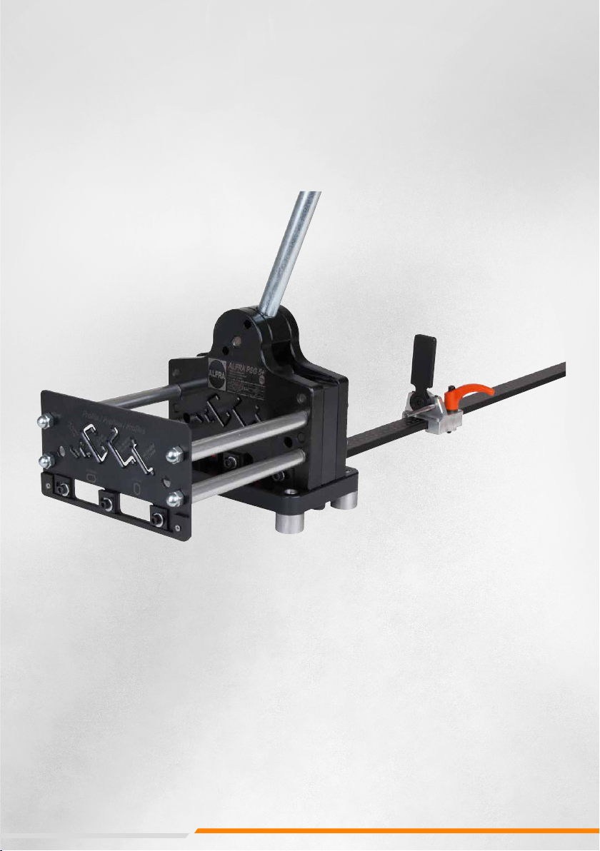
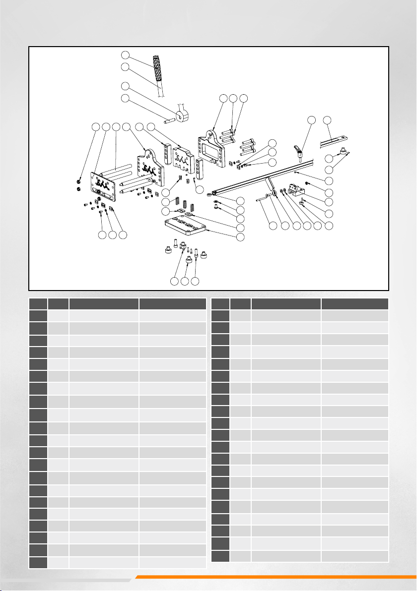
Profilschienenschneidgerät PSG5 Art.Nr.03001
POS-NR.
MENGE
Art.Nr.
Beschreibung 1
1
2 03001-005
Seitenstütze PSG5
2
1
DIN EN ISO8734-12x60-m6
Zylinderstift
3
1
03004-006
Exzenter B30
4
1
03004-007
Handhebelstange
5
1
189414301
TPE Handgriff D25x120
6
1
03001-003
Rückplatte PSG5
7
4
DIN 912 M10x50-8.8-A2R
Zylinderschraube schwarz verzinkt
8
4
DIN 912 M10x75-8.8-A2R
Zylinderschraube schwarz verzinkt
9
1
03004-021
Anschlagschiene mit Maßskala
10
1
03004-033
Fuss für Anschlagschiene
11 1
03004-032
Federdruckstück
12
1
03004-031
Klemmhebel
13
1
DIN439-M8-13 A2K
Sechskantmuttern flach
14
1
DIN EN ISO 8734-4x14-m6
Zylinderstift
15
1
03004-023
Klemmscheibe
16
1
03004-022
Anschlagschieber
17
1
DIN_PA6.6_M8x1,6
Unterlegscheibe
17a
1
DIN988-8x14x0,3 Unterlegscheibe
18
1
03004-026
Anschlagklappe
19
1
DIN7991-M8x25-8.8 A2K
Senkschraube
20
1
03001-035
Abstandsscheibe
21
1
DIN125-A10,5 A2
Scheibe
22
1
ISO7380-M10X16-A2
Flachrundschraube
23
1
03001-004
Grundplatte
24
2
DIN912-M10X30-8.8-A2K
Zylinderschraube
25
4
03004-008
Gerätefuss D28
26
4
DIN912-M5x18-A2K
Zylinderschraube
27 2
DIN913-M6x6-45H
Gewindestifte
28 3
03004-015
Druckfeder D15-L35
29 2
03001-022
Stempel
30
1
03001-023
Matrize 1
31
1
03001-023a
Matrize 2
32
10
03001-025
Plättchen
33 8
DIN125-A6,4-140HV-A2
Scheibe
34
8
DIN912-M6x10-8.8-A2R
Zylinderschraube
35
4
DIN985-M8-A2
Sechskantmuttern
36
1
03001-002
Scherplatte PSG5
37
4
03004-014
Gewindestange K240 L180
38
1
03001-001
Frontplatte PSG5
39
1
03001-017
Führungsplatte PSG5
40
1
DIN EN ISO 8734-6x60-m6
Zylinderstift
41
1
DIN 915 M5X16-45H
Gewindestift
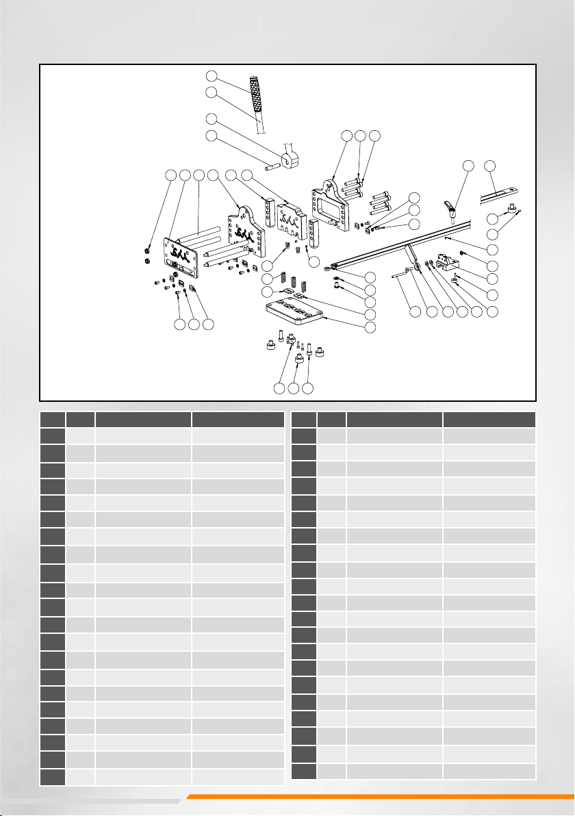
PIÈCES DE RECHANGE PSG +®
N°de produit 03001
Pos. Qty. N°de produit Description
1203001-005 support latéral PSG5
21DIN EN ISO8734-
12x60-m6 goupille cylindrique
3103004-006 Eccentric B30
4103004-007 ige de levier à main
51189414301 TPE Poignée D25x120
6103001-003 Plaque arrière PSG5
74DIN 912 M10x50-8.8-
A2R vis cylindrique noir
-gal- vanisé-
84DIN 912 M10x75-8.8-
A2R vis cylindrique noir
-gal- vanisé-
9103004-021 Barre d’arrêt avec mè-
tre-ruban
10 103004-033 pied pour l'arrêt
11 103004-032 Pièce de pression à
ressort
12 103004-031 Levier de serrage
13 1DIN439-M8-13 A2K Écrous hexagonaux
plats
14 1DIN EN ISO
8734-4x14-m6 goupille cylindrique
15 103004-023 Levier de serrage D20
16 103004-022 Glissoir d‘arrêt
17 1DIN_PA6.6_M8x1,6 Rondelle
17a 1DIN988-8x14x0,3 Rondelle
18 103004-026 Clapet d‘arrêt
19 1DIN7991-M8x25-8.8
A2K Vis à tête fraisée
20 103001-035 espaceur
Pos. Qty. N°de produit Description
21 1DIN125-A10,5 A2 Rondelle
22 1ISO7380-M10X16-A2 vis à tête plate
23 103001-004 Plaque de base
24 2DIN912-M10X30-8.8-
A2K vis cylindrique
25 403004-008 base de l'appareil D28
26 4DIN912-M5x18-A2K vis cylindrique
27 2DIN913-M6x6-45H Goujon fileté
28 303004-015 Ressort à pression en
haut D15-L35
29 203001-022 Poinçon
30 103001-023 Matrice 1
31 103001-023a Matrice 2
32 10 03001-025 tuile
33 8DIN125-A6,4-140HV-A2 Rondelle
34 8DIN912-M6x10-8.8-A2R vis cylindrique
35 4DIN985-M8-A2 Écrou hexagonal
36 103001-002 Plaque de cisaillement
PSG5
37 403004-014 Tige filetée K240 L180
38 103001-001 Plaque avant PSG5
39 103001-017 Plaque de guidage
PSG5
40 1DIN EN ISO
8734-6x60-m6 Goupille cylindrique
41 1DIN 915 M5X16-45H Goujon fileté