Algo 8128 User manual

Document 90-00066 Algo Communication Products Ltd (604) 454-3792
Page 1 www.algosolutions.com
8128 SIP LED Strobe Light
FW Version 2.3
Installation & Configuration
8128 Clear lens only
8128AClear lens with AMBER cover
8128BClear lens with BLUE cover
8128RClear lens with RED cover
8128ABR Clear lens with 3 color cover kit

Document 90-00066 Algo Communication Products Ltd (604) 454-3792
Page 2 www.algosolutions.com
CONTENTS
Important Safety Information ................................................................................. 4
About the 8128 Strobe ............................................................................................ 5
Common Applications .............................................................................................. 5
Quick Start .............................................................................................................. 6
What's Included ...................................................................................................... 7
Wiring Connections ................................................................................................. 8
Network Connection .................................................................................................8
Terminal Block Relay In ............................................................................................8
Terminal Block Relay Out ..........................................................................................8
Terminal Block Reset................................................................................................8
Web Interface Login ................................................................................................ 9
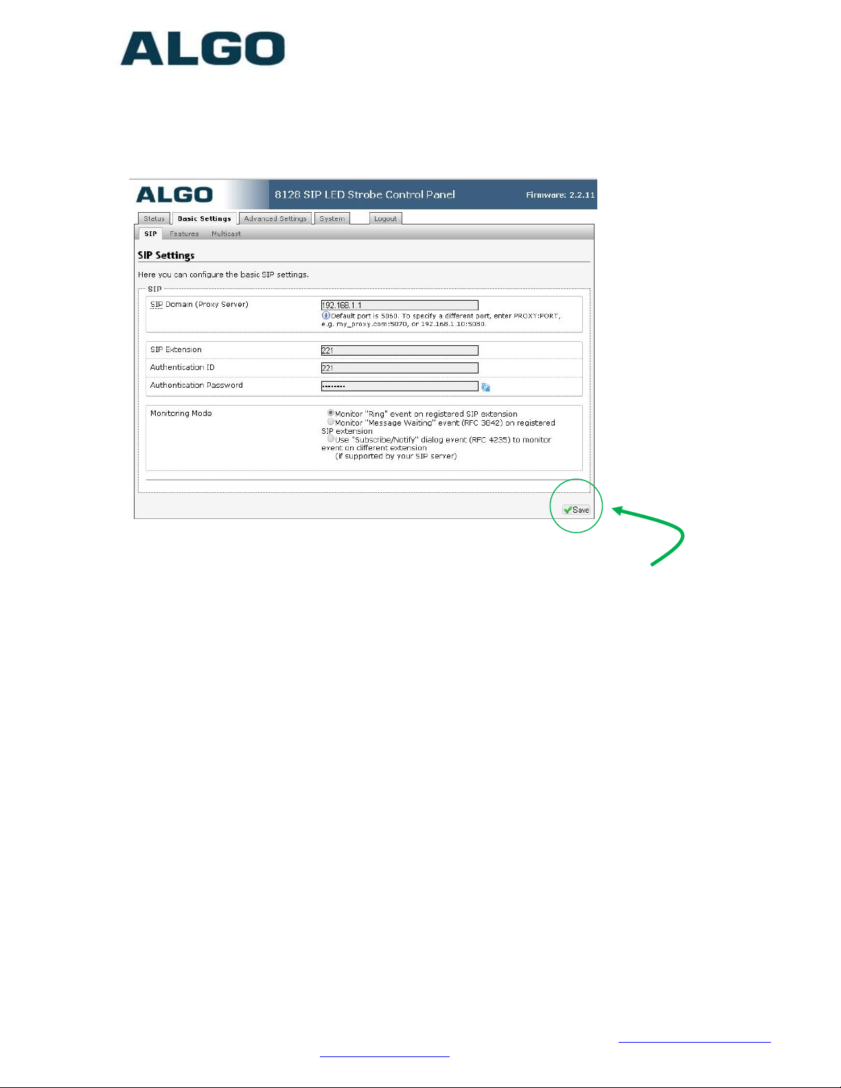
Basic Settings Tab - SIP ........................................................................................ 10
SIP Domain (Proxy Server) ..................................................................................... 10
SIP Extension........................................................................................................ 10
Authentication ID................................................................................................... 10
Authentication Password......................................................................................... 10
Monitoring Mode ....................................................................................................11
Activating 8128 Strobe Using Subscribe/Notify .......................................................... 11
Basic Settings Tab - Features ................................................................................ 12
Flash Patterns .......................................................................................................12
Flash Pattern Test .................................................................................................. 13
Cadence ............................................................................................................... 14
Relay Input Detection Mode .................................................................................... 14
Relay Input Action ................................................................................................. 14
Relay Output Mode ................................................................................................ 14
Multicast Overview ................................................................................................ 14
Multicast IP Addresses .......................................................................................... 15
Basic Settings Tab - Multicast Master Settings ...................................................... 16
Multicast Mode (Master Selected)............................................................................. 16
Master Zone..........................................................................................................16
Send Flash Pattern................................................................................................. 17
Send 8180-Compatible Control Signal ...................................................................... 17
Zone Definitions .................................................................................................... 17
Synchronization..................................................................................................... 17
Basic Settings - Multicast Slave Settings ............................................................... 18
Multicast Mode (Slave Selected) .............................................................................. 18
Slave Zones ..........................................................................................................18
Zone Definitions .................................................................................................... 19
Advanced Settings - SIP ........................................................................................ 19
Outbound Proxy..................................................................................................... 19
STUN Server ......................................................................................................... 19
Register Period (seconds) ....................................................................................... 20
Keep-alive Method .................................................................................................20

Document 90-00066 Algo Communication Products Ltd (604) 454-3792
Page 3 www.algosolutions.com
Server Redundancy Feature .................................................................................... 20
Backup Server #1..................................................................................................20
Backup Server #2..................................................................................................20
Polling Intervals (seconds) ...................................................................................... 20
Poll Active Server................................................................................................... 20
Automatic Failback.................................................................................................21
Polling Method.......................................................................................................21
Advanced Settings - Network ................................................................................ 21
Protocol................................................................................................................ 22
VLAN Mode ...........................................................................................................22
VLAN ID ............................................................................................................... 22
VLAN Priority.........................................................................................................22
Differentiated Services (6-bit DSCP value) ................................................................ 22
DHCP Timeout ....................................................................................................... 23
Advanced Settings - Administration ...................................................................... 23
Password .............................................................................................................. 23
Confirmation ......................................................................................................... 24
Device Name.........................................................................................................24
NTP Time Server.................................................................................................... 24
Introduction Section on Status Page......................................................................... 24
Log Level .............................................................................................................. 24
Log Size ............................................................................................................... 24
Log Method ........................................................................................................... 24
Log Server ............................................................................................................24
Hardware Watchdog............................................................................................... 24
SNMP Support (v1 get only).................................................................................... 24
Advanced Settings - Provisioning .......................................................................... 25
MD5 Checksum ..................................................................................................... 26
Generating a generic configuration file ..................................................................... 26
Generating a specific configuration file ..................................................................... 27
System - Maintenance ........................................................................................... 27
Download Configuration File .................................................................................... 28
Restore Configuration File ....................................................................................... 28
Restore Configuration to Defaults ............................................................................ 28
Reboot the Device.................................................................................................. 28
Firmware Image ....................................................................................................28
MD5 Checksum ..................................................................................................... 28
Upgrade 8128 Strobe Firmware ............................................................................... 28
System - Network Logging .................................................................................... 29
Optional Colored Lens Cover.................................................................................. 29
Specifications: ....................................................................................................... 30
FCC Compliance ..................................................................................................... 31

Document 90-00066 Algo Communication Products Ltd (604) 454-3792
Page 4 www.algosolutions.com
Important Safety Information
The 8128 Strobe is NOT INTENDED FOR FIRE ALARM
SIGNALLING APPLICATIONS.
The 8128 Strobe is intended for informative signaling in conjunction
with unified communication systems. The 8128 Strobe is suitable for
OSHA and ADA compliance when properly located and configured.
DO NOT LOOK DIRECTLY at the 8128 Strobe while operating
in close proximity as vision may be affected. The LEDs in the 8128
Strobe are classified according to the IEC 62471-2006 standard as
"RG-2" for risk group 2. This is defined as "Moderate risk. Does not
pose a hazard due to aversion response to bright light or thermal
discomfort".
PHOTO-SENSITIVITY in some people with epilepsy can trigger
seizures from flashing or flickering lights. It is possible that some flash
patterns of the 8128 Strobe could trigger a seizure for some individuals
under some conditions. High intensity patterns should only be selected if
necessary for the 8128 Strobe to be effective.
Wet or Outdoor Environments
The 8128 LED Strobe is intended for indoor or outdoor locations and
may be subjected to spray or weather provided the rear wiring cavity
is properly sealed to prevent water ingress.
Gaskets included with the 8128 LED Strobe may be effective against
water ingress on some, but not all surfaces in which case additional
protective measures must be taken such as a perimeter sealant.
CAT5 or CAT6 connection wiring to an IEEE 802.3af compliant
network PoE switch must not leave the building perimeter
without adequate lightning protection.
Relay input and output connections must not leave the building
perimeter without adequate lightning protection.

Document 90-00066 Algo Communication Products Ltd (604) 454-3792
Page 5 www.algosolutions.com
About the 8128 Strobe
The 8128 Strobe flash intensity can be chosen to suit the application and
environment. There are non-flashing patterns for passive, gentle
notification, and aggressive patterns for maximum conspicuity in busy
environments
The 8128 Strobe is typically wall or ceiling mounted. The eight efficient and
powerful LEDs cast light 360 x 180 degrees with some light illuminating the
surface surrounding the 8128 Strobe for additional visibility. Light output is
equally intense in every direction unless a directional pattern is chosen.
The 8128 Strobe can be activated by:
SIP Ring
SIP Message Waiting
SIP In-Use (Subscribe Notify)
Dry contact closure input
Multicasting
If multiple 8128 Strobes are required, the multicasting feature requires
only one of the 8128 Strobes to be activated by an input. The activated
8128 Strobe can simultaneously multicast as a master to activate the other
8128 Strobes configured as slaves.
The 8128 Strobe is configured from its web interface using a browser such
as Google Chrome, Firefox, or Internet Explorer (other than IE 9).
Common Applications
Telephone ring notification in noisy environments
Silent ring notification in quiet environments
Call center ACD queue threshold alert (by ringing)
In-use (off-hook, on-air) notification for co-workers
Message waiting notification
OSHA safety compliance
ADA compliance
Door open visual alarm
Voice paging pre-announce
Security notification

Document 90-00066 Algo Communication Products Ltd (604) 454-3792
Page 6 www.algosolutions.com
Quick Start
1. Connect the 8128 Strobe to a 802.3af PoE network using the RJ45
jack in the back recess of the housing.
2. Allow the 8128 Strobe time to boot, about 30 seconds. During boot
up the Strobe will turn on each LED individually as a test and then all
on at low intensity until booting is completed.
3. If there is no DHCP server found the 8128 Strobe will default to the
static IP address 192.168.1.111. Most often however the 8128
Strobe will be assigned an IP address. To determine the IP address
for the 8128 Strobe download the Algo locator tool to find Algo
devices on your network: www.algosolutions.com/locator
4. Access the 8128 Strobe web page by entering the IP address into a
browser and login using algo as the default password.
5. Enter the IP address for the SIP server into the SIP Domain field
under the BASIC SETTINGS - SIP tab.
6. Enter the SIP extension and password information.
7. Test by dialing the SIP extension for the Strobe . The Strobe should
flash in response to ring (the 8128 Strobe will not answer a ring
event).
Installation & Mounting
The 8128 Strobe can be wall or ceiling mounted. Concealed wiring may
enter from the wall into the wiring cavity. Alternatively, surface wiring may
enter through a channel from the bottom edge. The channel is intended for
cabling 0.2" or 5mm in diameter and is intentionally snug to protect against
moisture ingress.
The 8128 Strobe can be mounted in any orientation but both the bracket
and housing identify TOP. This keeps the bracket wiring channel on the
bottom and the RJ45 jack on the top side.

Document 90-00066 Algo Communication Products Ltd (604) 454-3792
Page 7 www.algosolutions.com
The mounting plate may be used to mount over flush or surface mounted
electrical boxes or mud rings and fits securely to a 2 gang electrical box for
installation with wiring conduit.
The 8128 Strobe is rated IP65 for wet locations however care must be
taken to ensure that water does not enter the wiring cavity. The supplied
gaskets or sealant must be used to protect the wiring cavity in wet
environments. In dry indoor environments the gaskets are not required. If
the wall gasket is used with surface wiring then the gasket should be
attached after placing the cable into the wiring channel.
The 8128 Strobe should not be installed beyond a building perimeter
without adequately protecting the building wiring from lightning surge.
What's Included
8128 Strobe unit with clear lens
Mounting bracket
Gaskets
Colored lens cover (if color option ordered)
This guide

Document 90-00066 Algo Communication Products Ltd (604) 454-3792
Page 8 www.algosolutions.com
Wiring Connections
Network Connection
Connect RJ45 jack from PoE network switch or non-PoE network
and 48V 350 mA IEEE 802.3af compliant power injector.
Terminal Block Relay In
By default, shorting these terminals will cause the 8128 Strobe to
activate.
Terminal Block Relay Out
By default these terminals provide a contact closure when the
8128 Strobe is active.
Terminal Block Reset
Connecting these terminals prior to power up will cause a reboot to
factory default settings. Maintain the connection from power up
until the 8128 Strobe LEDs turn on. Then release the connection
which will cause the 8128 Strobe to reboot with default
configuration.

Document 90-00066 Algo Communication Products Ltd (604) 454-3792
Page 9 www.algosolutions.com
Web Interface Login
The web interface requires a password which is "algo" by default. This
password can be changed using the Admin tab after logging in the first
time.

Document 90-00066 Algo Communication Products Ltd (604) 454-3792
Page 10 www.algosolutions.com
Basic Settings Tab - SIP
Note: Any time changes are made to settings in the web
interface the "Save" key must be clicked to save the changes.
SIP Domain (Proxy Server)
SIP Server Name or IP Address
SIP Extension
This is the SIP extension for the 8128 Strobe.
Authentication ID
May also be called Username for some SIP servers and in some cases
may be the same as the SIP extension.
Authentication Password
SIP password provided by the system administrator for the ID

Document 90-00066 Algo Communication Products Ltd (604) 454-3792
Page 11 www.algosolutions.com
Monitoring Mode
There are five ways in which the 8128 Strobe can be activated.
Dry contact input or multicast does not require registration with a SIP
server and is discussed elsewhere in this guide.
The monitoring mode selects whether SIP activation is by ring,
message waiting, or subscribe/notify as described below.
Activating 8128 Strobe from SIP Ring Event
Set Monitoring Mode to "Monitor Ring". When a call is made to the
SIP extension the 8128 Strobe will flash. Often, the 8128 Strobe will
be part of a hunt group or ring group to flash in conjunction with a
telephone.
Activating 8128 Strobe from SIP Message Waiting Event
Set Monitoring Mode to "Monitor Message Waiting". When a message
is left for the SIP extension then the 8128 Strobe will flash.
Activating 8128 Strobe Using Subscribe/Notify
If the 8128 Strobe alert mode is set to use Subscribe/Notify then
an additional field appears asking for the Alert Extension. This is the
SIP extension which the 8128 Strobe will monitor for events, which
may be different from the SIP extension of the 8128 Strobe itself.

Document 90-00066 Algo Communication Products Ltd (604) 454-3792
Page 12 www.algosolutions.com
Subscribe/notify per SIP RFC 4235 allows a SIP extension to request
status information for other SIP extensions.
The subscribe/notify information available from SIP servers varies by
vendor and release. As of FW Version 2.3 only ring and in-use are
enabled however it may also be possible to detect events such as
message waiting or ACD queue status. Please contact Algo for
current information.
Basic Settings Tab - Features
Flash Patterns
Choose from 16 available patterns. The 8128 Strobe contains 8 high
intensity LEDs each capable of producing 643 lumens or 198 Candela.
In addition to being very bright, the LEDs can be fired
simultaneously or individually for interesting effects. Light output is

Document 90-00066 Algo Communication Products Ltd (604) 454-3792
Page 13 www.algosolutions.com
equally bright over 360 x 180 degrees and also illuminates the
mounting surface for even greater conspicuity.
Patterns 0 & 1 do not fire the center LEDs and are intended for a
ceiling mount application where light is required in every horizontal
direction but not straight down.
Pattern 11 does not fire the top and bottom LEDs and is intended for
a wall mount application in a hallway with maximum conspicuity to
the left, right, and center.
Flash Pattern Options Table
PHOTO-SENSITIVITY in some people with epilepsy can trigger
seizures from flashing or flickering lights. It is possible that some
flash patterns of the 8128 Strobe could trigger a seizure for some
individuals under some conditions. High intensity patterns should
only be selected if necessary for the 8128 Strobe to be effective.
Flash Pattern Test
After selecting the flash pattern the test button may be used to
activate the 8128 Strobe.
No Description Wall Ceiling High Med Low
15 Classic strobe slow ● ● ●
14 Classic strobe medium ● ● ●
13 Classic strobe fast ● ● ●
12 Flashing ● ● ●
11 Side to side ● ●
10 Pulse ● ● ●
9 Steady bright ● ● ●
8 Steady dim ● ● ●
7 Rotating strobe ● ● ●
6 Multi-strobe slow bright ● ● ●
5 Multi-strobe slow dimmed ● ● ●
4 Multi-strobe fast bright ● ● ●
3 Multi-strobe fast dimmed ● ● ●
2 Multi-strobe and dim holdover ● ● ●
1 Rotate slow ● ●
0 Rotate fast ● ●
Application
Intensity/Strobe

Document 90-00066 Algo Communication Products Ltd (604) 454-3792
Page 14 www.algosolutions.com
Cadence
The 8128 Strobe may be continuously active during an event, or
emulate a telephone ring on/off cadence. Using a cadence will also
ensure multiple 8128 Strobes using multicast remain synchronized.
Relay Input Detection Mode
The relay input feature can be set to be active when open or closed.
This will depend on the triggering source. Generally, normally closed
circuits are preferred so that a wiring open fault will initiate activity.
Relay Input Action
The relay input may be used to flash the 8128 Strobe while the input
is active, or latch the 8128 Strobe in an active state until cancelled
by ringing the SIP ring extension.
For example, if the 8128 Strobe is connected to a door contact it can
be made to flash only while the door is open (input active). Or the
door open event can trigger the 8128 Strobe which will remain active
even after the door is closed. The 8128 Strobe in this mode (call to
cancel) must receive a SIP ring event to reset.
Relay Output Mode
When the 8128 Strobe is active this contact output will be either
closed or open according to this selection.
Multicast Overview
The 8128 Strobe is able to send or receive IP multicast messages
over the network.
Without multicast, multiple 8128 Strobes would all require their own
SIP extensions and then be added to a hunt group or ring group for
simultaneous activation.
Multicasting offers an alternative that requires only one SIP extension
and reduces network traffic. The first 8128 Strobe deployed can be
configured as a multicast master, so that whatever flash pattern is
selected is also broadcast to the network using a multicast IP
address. All of the other 8128 Strobes are configured as multicast
slaves and will activate in response to the multicast message.

Document 90-00066 Algo Communication Products Ltd (604) 454-3792
Page 15 www.algosolutions.com
The slave 8128 Strobes require a PoE network connection but do not
require registration to the SIP server.
In fact, since the 8128 Strobe can also be activated by dry contact
closure, it is possible to have one or multiple 8128 Strobes activate in
unison over multiple sites without any SIP server at all.
Multicast IP Addresses
Each 8128 Strobe has its own IP address, and shares a common
multicast IP and port number (multicast zone) for multicast packets.
The master unit transmits to a configurable multicast zone, and all
the slave units listen to the multicast zones assigned to them. When
a master unit receives a valid SIP ring event, it will flash locally and
also send out a special packet to the multicast zone. The network
switches and router see the packet and deliver it to all the members
of the group. The multicast IP and port number must be the same on
all the master and slave units of one group. The user may define
multiple zones by picking different multicast IP addresses and/or port
numbers.
1. Multicast IP addresses range: 224.0.0.0/4
(from 224.0.0.0 to 239.255.255.255)
2. Port numbers range: 1 to 65535
3. By default, the 8128 Strobe is set to use the
multicast IP address 224.0.2.60 and the port
numbers 50000-50008
Make sure that the multicast IP address and port number do not
conflict with other services and devices on the same network

Document 90-00066 Algo Communication Products Ltd (604) 454-3792
Page 16 www.algosolutions.com
Basic Settings Tab - Multicast Master
Settings
Multicast Mode (Master Selected)
If master is enabled the 8128 Strobe will broadcast an IP stream
when activated in addition to flashing. This option is available for all
activation methods (although note that the 8128 Strobe cannot be
both a multicast master and slave simultaneously).
Master Zone
Select the multicast zone to broadcast on.

Document 90-00066 Algo Communication Products Ltd (604) 454-3792
Page 17 www.algosolutions.com
Send Flash Pattern
Enabling this option means all 8128 Strobes in the multicast zone will
mimic the flash pattern of the multicast master 8128 Strobe
regardless of their individual settings. If disabled then each
Strobe may have a unique flash pattern according to its settings.
Send 8180-Compatible Control Signal
This option allows the 8128 Strobe to activate Algo 8180 Audio
Alerters via multicast.
www.algosolutions.com/8180
Zone Definitions
Multicast IP addresses and ports are configured by default. These
typically do not need to be changed unless they conflict with other
multicast addresses on the network. If changed they must be
changed on all 8128 Strobes in the multicast group.
Multicast zones are assigned a priority based on the list position.
Each 8128 Strobe multicast slave will flash from the highest priority
active zone.
Synchronization
For flash patterns other than "steady" multiple 8128 Strobes
activated by multicast will be synchronized only if the Cadence option
is chosen to NOT be continuous under the Basic Settings tab.

Document 90-00066 Algo Communication Products Ltd (604) 454-3792
Page 18 www.algosolutions.com
Basic Settings - Multicast Slave Settings
Multicast Mode (Slave Selected)
If slave is enabled the 8128 Strobe will activate when receiving a
multicast message. Depending on the settings of the Master, the
8128 Strobe will mimic the master flash pattern or use its own
selected flash pattern
Slave Zones
Select one or more multicast zones for the 8128 Strobe to monitor.
Note that multicast zone priority is based on the zone definition list
order (top to bottom).

Document 90-00066 Algo Communication Products Ltd (604) 454-3792
Page 19 www.algosolutions.com
Zone Definitions
See information in previous section under Master settings
Advanced Settings - SIP
Outbound Proxy
IP address for outbound proxy. A proxy (server) stands between a
private network and the internet.
STUN Server
IP address for STUN server if present.

Document 90-00066 Algo Communication Products Ltd (604) 454-3792
Page 20 www.algosolutions.com
Register Period (seconds)
Maximum requested period of time where the 8128 Strobe will re-
register with the SIP server. Default setting is 3600 seconds (1 hour).
Only change if instructed otherwise.
Keep-alive Method
If Double CRLF is selected the 8128 Strobe will send a packet every
30 seconds (unless changed) to maintain connection with the SIP
Server if behind NAT.
Server Redundancy Feature
Two secondary SIP servers may be configured. The 8128 Strobe will
attempt to register with the primary server but switch to a secondary
server when necessary. The configuration allows re-registration to
the primary server upon availability or to stay with a server until
unresponsive.
Backup Server #1
If primary server is unreachable the 8128 Strobe will attempt to
register with the backup servers. If enabled the 8128 Strobe will
always attempt to register with the highest priority server.
Backup Server #2
If backup server #1 is unreachable the 8128 Strobe will attempt to
register with the 2nd backup server. If enabled the 8128 Strobe will
always attempt to register with the highest priority server.
Polling Intervals (seconds)
Time period between sending monitoring packets to each server.
Non-active servers are always polled, and active server may
optionally be polled (see below).
Poll Active Server
Explicitly poll current server to monitor availability. May also be
handled automatically by other regular events, so can be disabled to
reduce network traffic.
Other manuals for 8128
1
This manual suits for next models
4
Table of contents
Other Algo Lighting Equipment manuals
Popular Lighting Equipment manuals by other brands

Ibiza
Ibiza TINYLED-LASRGB manual

Lightolier
Lightolier Lighting Systems EC2-8 Specification sheet

Ansorg
Ansorg Simpless SNM 06SNM Series installation manual

AAA-LUX
AAA-LUX WS Series installation guide

Evenlite
Evenlite CURVE Installation and operating instructions

Elephant
Elephant SUPER DENSE LOOP-LOC MESH Care & maintenance